
Abstract
Blast load and its effects on transportation infrastructure especially bridge structures have received considerable attention in recent years. The RC bridge columns are considered as the most critical structural members because their failure leads to collapse of the bridge. Although RC bridge columns are typical axial load-carrying components, the studies on blast-resistant capacity of RC bridge columns usually neglect the axial load effect since it is commonly assumed that neglecting the axial load leads to conservative predictions of column responses. This assumption is true when column failure is governed by flexural response since axial compressive load generates a prestress in column which compensates concrete tensile stress induced by bending response. When subjected to blast loads, column response however could be governed by shear response. In this case neglecting axial loading effect does not necessarily lead to conservative predictions of column responses. In this study, high-fidelity finite element (FE) models for both non-contact explosion and contact explosion were developed in LS-DYNA. The FE models were validated with field blast test data. Subsequently, intensive simulations of the RC bridge columns with and without axial load subjected to a wider range of blast loading scenarios, including far-field, near-field and contact explosion were conducted. The influence of axial load on the dynamic performance of RC bridge columns corresponding to different blast loading scenarios was discussed.
Introduction
Performance of transportation infrastructure especially bridge structures subjected to blast loads has received considerable attentions in recent years. For common bridge structures, the dynamic response of their columns to blast loads is usually deemed as the most important in a protective analysis and design because bridge column failures are more likely to cause partial or even progressive collapse of the bridge.
In recent years, extensive researches on the effect of blast loads on reinforced concrete (RC) bridge columns have been presented. Based on the basic assumption that ignoring the axial load is usually conservative for typical bridge columns subjected to lateral blast loads, Williamson et al. (2010) conducted a series of blast tests on RC bridge columns without applying axial loads or weight the column carries. In the first phase, scaled bridge columns were tested with relatively large standoffs to gain a better understanding of the action of blast loads on the columns, variation law of pressure and impulse with time and position were also obtained; in the second phase, half-scale specimens were tested with small standoffs and failure modes of different columns were obtained. Yuan et al. (2017) performed comprehensive experimental and numerical investigations into the behavior of RC bridge columns with square and circular cross sections under 1 kg TNT contact explosion. Axial load on the column was not considered in the experimental tests either. Results from the numerical simulation are compared with the experimental results, it was shown that the LS-DYNA numerical models gave reasonable predictions of the structural response of bridge columns under contact explosion. Echevarria et al. (2015) conducted blast testing of concrete-filled fiber-reinforced polymer tube and conventional RC bridge columns that having comparable flexural capacities without axial loads. It was found the damaged CFFT columns exhibited superior strength and ductility retention compared with the damaged RC columns. Dua et al. (2020) investigated responses of rectangular RC columns to contact explosion experimentally and numerically. The blast tests were conducted without axial forces applied to the columns. The variation in widths of the cross-section was taken into consideration. The numerical results show good agreement with the experimental results. It was found that increasing the width of the rectangular RC columns can effectively mitigate contact explosion damage. Fujikura et al. (2008) proposed multihazard bridge pier concept and investigated a 1/4 scale multi-column bent pier with concrete-filled steel tube (CFST) circular columns, the results indicated that CFST columns show ductile behavior under blast loading. It should be noted that although the axial force was not considered during the blast testing, secondary moment effects were analyzed for all the tested columns, it was found that the deformed columns were stable against P-Delta failures. Considering the CFST columns were not commonly used, they carried out a follow-up blast testing on seismically designed bridge piers, which are a 1/4 scale column bent pier with ductile RC columns and nonductile steel jacketed RC columns (Fujikura and Bruneau, 2011). In this study, a column was selected to do axial force-moment interaction analysis, and this column provided satisfactory performance for the considered seismic loading. However, all the tested columns did not show ductile performance and exhibited shear failure at the base under blast loads. Accordingly, it was deemed that the axial load effects on bridge columns under blast loading should be investigated especially the effects on direct shear resistance. Another study was then conducted to analytically investigate multihazard-resistant bridge piers with CFST columns subjected to blast loading (Fujikura and Bruneau, 2012). A single-degree-of-freedom (SDOF) analysis method and a fiber-based analysis method was used. Simple P-Delta analyses were carried out separately to examine whether the deformed column would buckle due to the gravity load of the superstructure after the blast, the results showed that the columns remain stable under the axial load.
Besides the aforementioned studies, there exists some numerical studies of RC column responses under combined effects of axial and blast loads. A study by Islam and Yazdani (2008) developed a numerical model to investigate the blast-resistance capacity of bridge components under blast loads. The axial load effects of superstructures on bridge columns were included in the analysis, the blast loads were assumed as uniformly distributed along the centerline of the columns, corresponding to far-field explosion scenarios, therefore flexural response was the primary response and failure mode as observed in numerical simulations. Another study on performance of highway bridges subjected to blast loads by Yi et al. (2013a, 2013b) reported that under severe blast loading condition (i.e., close-in or contact explosion), bridge piers may exhibit plastic strains as high as 20%, the large deformation of a column results in extra forces applied on the element because of the P-Delta effect associated with the axial load. It was also found that although using concrete with a 69 MPa compressive strength could reduce column damage of the considered bridge, bridge piers tended to fail in shear subjected to a high level of blast loads. Liu et al. (2015) employed a simplified approach (i.e. LBE) for applying blast loads and conducted numerical simulation with LS-DYNA of the column bent pier of a bridge (Yi et al., 2013a, 2013b), the axial load applied by superstructures and self-weight were considered in the study. The results indicated that the strengthened transverse reinforcement could improve the capacity of bridge piers to resist blast loads dramatically. Astarlioglu et al. (2013) conducted numerical studies on RC columns subjected to axial and blast-induced transverse loads utilizing an advanced single-degree-of-freedom (SDOF) model, the results indicated that the level of axial compressive load had a significant effect on the response of RC column. It was also found that for high pressure and short duration loads, even if the axial load on the column was relatively small, its blast resistance capacity would be greatly reduced. This conclusion is contrary to the response of columns under combined flexural and axial loads when subjected to quasi-static loads. Crawford (2013) developed high-fidelity physics-based (HFPB) analytic models to investigate blast threats to RC columns from vehicle borne improvised explosive devices (VBIEDs). The gravity load was taken into consideration in the simulations, the results showed that even though little lateral deflection occurred due to the brittle responses associated with small standoff explosion, the response to the gravity load after application of the blast load resulted in catastrophic failure.
Recently, Chen et al. (2019) performed experimental and numerical investigation into the influence of axial load ratio (ALR) on the behavior of RC column under close-in explosion. It was concluded that the increase of ALR is beneficial to the blast resistance of RC column at scaled distance greater than 0.4 m/kg1/3, but the increase of ALR usually intensifies the shear damage of RC column at scaled distance less than 0.4 m/kg1/3, it was found that as the ALR increases, the column failure mode alters from the typical flexural failure to typical compression-shear failure. At the scaled distance of 0.4 m/kg1/3, there exists an ALR limit of 0.4, above which the failure of column suffers from the compression-shear failure. Liu et al. (2019) investigated the blast performance of RC columns under the combined action of axial load and close-in explosion experimentally, the results showed that when the scaled distance was relatively large, the columns with higher axial loads suffered less damage than columns with smaller axial loads under the same loading scenario. With the decrease of the scaled distances, the axial load increased the level of damage to RC columns. These results clearly indicate that the assumption of neglecting axial load would lead to conservative predictions of column responses to blast load is not necessarily correct. It should be noted that although the aforementioned studies (Chen et al., 2019; Liu et al., 2019) did take into account axial load effects, the investigations focused on RC columns in building structures rather than RC bridge columns, the ALR were 0.2, 0.4, 0.6, and 1.0 in Chen et al. (2019) and 0.2, 0.4, 0.6 in Liu et al. (2019). However, unlike columns in buildings which typically experience service loads above their balance point, RC bridge columns typically sustain in-service axial loads that are below their balance point on an interaction diagram of axial force and bending moment. The conclusion for RC columns in building structures might not be suitable for RC bridge columns. A systematic investigation of the influences of axial force on blast responses of RC columns is needed.
It is noticed from the above literature review that study of blast-resistant capacity of RC bridge columns that takes into consideration the axial load effect is rather limited. The main reason is that some researchers assume that axial load application is beneficial to the column lateral blast resistance. In fact, inclusion of axial load alters the internal stress distribution, the shear stress in the concrete column could increase with the axial load, and this increment may lead to the column more vulnerable to brittle shear damage under blast loads. Moreover, axial load induces P-δ effect, which could be detrimental when lateral response is relatively large. Winget et al. (2005) pointed out that the interaction of axial response and flexural response should be verified to ensure that neglecting the small compressive axial loads in the pier is conservative. In addition, unlike buildings, bridges are designed to provide open access to the public, so they may be more vulnerable to close-in or contact explosions. Studies have pointed out that the likelihood of terrorists attacking bridge structures increases with the decrease in the amount of explosives used, meaning they are more likely to attack bridges at close range with small amounts of explosives. Winget et al. (2005) considered that contact explosion targeting bridge columns may be the first choice for a terrorist attack. However, there is almost no relevant study in the open literature on RC bridge columns with axial loads subjected to contact explosion. Therefore, it is necessary to study the influences of axial load effect on RC bridge columns subjected to a wider range of blast load scenarios, including far-field, near-field and contact explosions.
In the present study, the blast load resistance of RC bridge columns with or without axial load were numerically investigated. The finite element models for non-contact and contact explosion were calibrated first through simulation of existing experimental tests and comparison of the numerical and experimental data. Varying blast scenarios including far-field, near-field and contact detonations were then considered to simulate bridge column responses using the calibrated numerical model. Based on the numerical simulation results, influence of axial load on RC bridge columns against blast loads was discussed.
Numerical model calibration
In the present study, numerical simulations were carried out with commercial hydro-code LS-DYNA. This software employs explicit algorithm and has been extensively used for predicting the dynamic response of RC structures subjected to blast loads (Chen et al., 2014; Li and Hao, 2013).
RC column responses under non-contact explosions are mainly characterized by flexure or shear damage that can be modelled with relatively coarse meshes, while contact explosion generates intensive stress waves that result in highly localized structural response and damage such as concrete spalling, cratering, and breaching, element with very small size must be used to obtain the accurate structural response (Luccionia and Aráozb, 2011). Therefore, numerical models for non-contact and contact explosions should be developed separately with different methods of simulation, which implies a need to conduct calibrations for both non-contact and contact blast scenarios to validate the accuracy and reliability of developed numerical models.
Calibration of numerical model of column under non-contact explosion
Experimental descriptions and finite element model
The test carried out by Baylot and Bevins (2007) to investigate the dynamic response of the lower central column of a 1/4 scale RC frame structure under blast loads was adopted in this study to verify the numerical model for predicting responses of reinforced concrete column subjected to non-contact explosion loads. The test setup is shown in Figure 1(a). A 7.1 kg hemisphere shaped C4 high explosive (equivalent to 8 kg TNT) was detonated at a standoff distance of 1.07 m in the test, with the detonation height of 305 mm above the ground. The height of the tested exterior central column is 910 mm, and the cross section is 89 mm by 89 mm as shown in Figure 1(b). The diameters of vertical reinforcements and stirrups are 7.1 mm and 4 mm, respectively. The shear reinforcement diameter is 3.85 mm. More detailed information of the test can be found in Baylot and Bevins (2007).
Tested and finite element model of column used for model calibration. (a) Picture of test setup used for model calibration, (b) cross section of tested column, and (c) finite element model.
In the previous studies, Shi et al. (2008), Mutalib and Hao (2011) have conducted the numerical analysis of the tested column and compared their results with those obtained in the test. In this study, 8-nodes constant stress solid element (SOLID_164) with 1-point quadrature integration and 3-nodes beam element (BEAM_161) with 2 × 2 Gauss quadrature integration were employed to model concrete and steel reinforcement, respectively. The finite element model of the column can be found in Figure 1(c). Convergence test was carried out by halving the mesh size from 20 mm to 10 mm and then 5 mm. According to the comparison of the deflection at column mid-span, the 5 mm element can provide the most accurate results, but it takes much longer simulation time and larger computer memory than the 10 mm element, which can also make a reasonable prediction of the column response, so the 10 mm element size was used in the numerical model for the balance between accuracy and efficiency. The nodes of the footing in the FE model were constrained in both horizontal and vertical directions, while that of the top of the column were constrained only in horizontal directions. In addition, according to the static service load carried by the column, a uniform axial pressure of 2.1 MPa was applied to the top surface of the column before applying the blast loading.
Material model
Concrete material can be simulated using several existing models in LS-DYNA, including *Mat_Johnson_Holmquist_Concrete (MAT_111), *Mat_ Pseudo_Tensor (MAT_16), *Mat_Brittle_Damage (MAT_ 96), *Mat_CSCM_ Concrete (MAT_ 159) and *Mat_Concrete_Damage_Rel3 (MAT_72_ REL3), etc. Among these models, the material model MAT_72_REL3 was adopted in the current study. This material model is based on plasticity, the damage softening after failure and strain rate effect are included in this model. Mat_ Piecewise_Linear_Plasticity (MAT_24) was employed to model both the longitudinal reinforcement bars and stirrups, and the strain rate effect was also considered in the study. The primary advantage of this model is that it allows users to define their own selected stress strain curves and strain rate curves. The material failure is based on a plastic strain or a minimum time step size. The material properties of concrete and steel reinforcement are tabulated in Table 1.
Parameters for material models.
Strain rate effect
It is commonly acknowledged that concrete and steel are rate sensitive. The equations derived by Hao and Hao (2014) were applied in the current study to calculate the dynamic increase factors (DIF) for concrete at different strain rates. In these equations, the influence of lateral inertial confinement and end friction confinement in impact testing on DIF is removed to obtain more accurate relationship to model the DIF of concrete material. For normal strength concrete, the DIFs for compressive strength are given by:
where
For normal strength concrete, DIFs for tensile strength are given by:

where
The DIF for steel is defined as given below (Malvar and Crawford, 1998):


where
Blast load modeling
The measured peak pressure along the column height in the blast testing was presented in Baylot and Bevins (2007) and shown in Figure 2. Apparent gradients in pressure near the ground surface can be observed from the test result. This can be attributed to the shock wave-ground interaction which strengthen the blast wave. Accordingly, the blast loads were simplified as a triangular pressure time history and imposed on the column segmentally. The details of blast load distribution along the column height used as input in this study is given in Table 2.
Measured peak pressure along the column height.
Blast load distribution.
Results and comparison
Figure 3 displays the comparison of displacement-time histories recorded in the test and obtained in numerical predictions. Numerical predictions in some other studies were also included in the figure for comparison. The maximum deflection and residual deflection at column mid-span is around 11.5 and 6.9 mm, respectively. The simulation results are consistent with the experimental results, indicating the numerical model gives reliable predictions of RC column response to blast load from non-contact explosions.
Comparison of displacement-time histories.
Calibration of numerical model of column under contact explosion
Arbitrary Lagrangian-Eulerian (ALE) capability of LS-DYNA, which can simulate the formation and propagation of the shock wave and stress wave as well as the shock wave-structure interactions, was adopted in the simulation of contact blast. Since no effective overpressure data could be measured during the contact blast tests on the tested column, to validate the model, the calibration for contact explosion includes the following steps. First, the recorded free-field pressure during the blast test below the bridge deck carried out by authors was used to verify the ALE capabilities to model shock wave propagation and reflections. Next, the model was calibrated by comparing the recorded structural responses and damage with the respective numerical predictions. Since the numerical model for predicting RC column responses and damage subjected to contact explosion load has been verified and presented in the previous study (Yuan et al., 2017), the model calibration was not repeated here for brevity. Hence only the calibration of numerical model in predicting explosion induced shock wave propagation was described herein. The inputs for the TNT explosive material and the air as well as the mesh size of the air domain and explosive in Yuan et al. (2017) are the same as those given as follows.
Test setup
The setup of the blast test below the bridge deck is shown in Figure 4. The prototype bridge is a 40 m span continuous T-beams bridge with prestressed concrete. Due to constraints with the maximum possible blast charge weight that could be used at the test site and specimen cost considerations, test specimen dimensions were set to be 1/5 scale of the prototype bridge. The span of the bridge specimen is 8 m. Considering the conditions of the test site, only two spans were fabricated with a total length of 16 m. The T-beams is composed of five single T-beam in the transverse direction, with a width of 0.5 m for a single T beam. The substructure of the bridge specimen is a double-column pier. The 2 kg TNT explosive was suspended from the T-beams, and the explosive was centered along the longitudinal and transverse directions, a steel plate was placed under the explosive to simulate a rigid ground. There was a free-field gauge located at 0.2 m above the ground and 2 m from the centre of the explosive. There were also pressure gauges installed on the column and T-beam, as these data were not used in this study, no detailed explanation was presented here.
Experiment setup.
Finite element model
In the simulation, the bridge, explosive and air were modelled with solid element. The bridge was modelled with Lagrangian mesh while the air and explosive (TNT) were simulated with Euler mesh. In order to conduct numerical simulation effectively and efficiently, two assumptions were made here: (1) The ground was assumed to be a rigid plane, that is, an ideal reflective surface without considering the ground cratering; (2) The structural members were assumed to be rigid bodies, and the deformation of the members under explosive load was not taken into consideration. The rigid ground surface was explicitly modelled using the *RIGIDWALL_PLANAR keyword to consider the blast wave reflection off the ground. The details of finite element models are shown in Figure 5.
Three-dimensional finite element model.
Figure 6 displays the air domain with a dimension of 4400 mm × 3080 mm × 1030 mm. The dimension of the rectangular block explosive is 140 mm × 100 mm × 65 mm in X, Y, and Z direction, respectively. It should be noted that the air and explosive model utilizes 1/2 symmetry to reduce the computational demand of the analysis as shown in Figure 6. The mesh size for air model is a uniform 0.02 m while the explosive block embedded in the air has a refined mesh size less than 0.02 m. The element sizes were determined by convergence test on three different combinations of element size during preliminary modelling. Transmitting boundary condition was applied to the side and end faces of the air domain model to avoid wave reflection in the simulation.
Detailed finite element model of air and explosives.
Material model
The bridge was modelled by *Mat_ Rigid material model.
Air was modelled using the *Mat_Null constitutive model and linear polynomial Equation of State (EOS). The EOS is linear in internal energy per unit initial volume, E. The pressure was defined by the following equation:

where C0-C6 are material parameters;
For TNT modelling, a *Mat_High_Explosive_Burn constitutive model and JWL_EOS were used, the pressure was defined as,

where p is the pressure, V is the specific volume, E is the energy per initial unit volume; A, B, R1, R2, and
Simulation setup
To enforce symmetry conditions on the plane of symmetry, the two rotational degrees-of-freedom parallel to the symmetry plane and the translational degree-of-freedom perpendicular to the symmetry plane were restrained. *Boundary_Non_ Reflecting was applied to all the free boundaries of the air model except the plane of symmetry to ensure the blast wave do not reflect back into the computational domain. The Lagrangian mesh (structural elements) was coupled to the Eulerian mesh (air and explosive elements) through *CONSTRAINED_LAGRANGE _IN_SOLID to link the air domain with the ground and bridge structure.
Results and comparison
Figure 7 illustrates the comparison of free-field overpressure time history between numerical and simulation results. The measured and simulated peak pressure is 0.52 and 0.51, respectively; the measured and simulated positive impulse is 0.303 and 0.249, respectively. The computed peak pressure is 2% lower than its corresponding experimental value, and the computed impulse is 18% lower than its corresponding experimental value. In addition, the time-of-arrival for the simulated pressure-time curve is greater than that of the experimental data. These observations are not surprising for two reasons. First, the airblast model developed in LS-DYNA has some deficiencies. Williams (2009) has also observed the under-prediction of pressures and impulses when modelling airblast with ALE algorithm in LS-DYNA, he believes that the defects are resulted from insufficient explosive yield that occurs very early in time during the explosive burn phase, which will lead to a certain degree of energy “leakage,” making the numerical simulation results smaller than the measured value. Second, the mesh of the air and explosives model is not fine enough. Generally speaking, in the numerical simulation of explosion and shock wave propagation in air, the smaller the mesh size, the higher the accuracy of the simulation results, but at the same time, the increase in the number of meshes will lead to a substantial increment of computational time and computer memory. The numerical model herein was established on the basis of limited available computing resources, taking into account the balance of computing efficiency and computing accuracy as much as possible. Moreover, due to a series of small-amplitude oscillations, the measured time-history curve of overpressure is not as smooth as that obtained by numerical simulation. One possible reason for the inconsistency is that the field test conditions are not ideal, which means that it is difficult to completely avoid differences between numerical models and test results. In general, the numerical model in LS-DYNA can reflect the overpressure in the test accurately, it can be used to characterize the blast loads on RC columns.
Comparison of measured and simulated free-field overpressure time history.
Numerical simulations
The above two calibrated numerical models were used in this study to simulate dynamic responses of RC columns to non-contact and contact blast loads, respectively.
Column configurations
In the following numerical simulations, a generic standalone RC bridge column with circular cross-section was considered. It should be noted that some previous studies (Shi et al., 2007; Williams and Williamson, 2011; Yuan et al., 2017) have proved the section geometry has significant influence on the interaction between blast wave and the column, and these literatures have also proved that a standalone column with circular cross section experiences substantially less net blast load and resultant impulse than that on rectangular columns owing to shock wave refraction. Therefore, a circular-shaped column would be a better choice for blast-resistance design of bridge columns. The clear height of the column is 3700 mm, the diameter is 400 mm for the column. The concrete material considered in the present study is of 40 MPa class. Ribbed steel bars HRB400 with a diameter of 12 mm and nominal yield strength of 400 MPa were used as longitudinal reinforcement. The plain roller steel bars HPB300 with a diameter of 8 mm and nominal yield strength of 300 MPa were used as stirrups. The geometric dimensions of the RC piers and reinforcement arrangement are illustrated in Figure 8.
Geometric dimensions and reinforcement arrangement of the specimen (unit: mm).
Figure 9 presents the finite element model of the column for non-contact and contact explosions. For the column model corresponding to non-contact explosions, the mesh size is 10 mm along the height except for the foundation. For the column model corresponding to contact explosions, the mesh size is 8 mm in the region close to the charge and 20 mm for the remaining part. The dimension of the air domain is 2 m × 2 m × 1.3 m. It should be noted that the mesh size of the air domain is uniform 0.02 m except for the location where the explosive was placed, which is consistent with that of the verified model for contact explosion in Yuan et al. (2017). The total charge weight is 1 kg. The element sizes in the present study were determined from convergence test. It was found that the use of smaller elements for concrete and reinforcement results in similar simulations but increases the calculation time enormously. As shown in Figure 9, the boundary condition was assumed to be a propped cantilever, that is, a column is fixed at one end and is simply supported at the other end. This boundary condition simulates a scenario in which the location of an explosion is directly beneath the deck and directly to the side of a column, assuming the superstructure provides lateral restraint. Moreover, this idealized support was considered to provide a conservative estimate of shear demand for a blast-loaded RC bridge column (Williams and Williamson, 2011).
Finite element model of the column for non-contact and contact explosions.
In design of bridge columns, the axial load from the bridge deck is typically taken as either 0.1
To investigate the effects of axial force on bridge columns, responses of columns with axial load and without considering axial load subjected to blast loads from far-field, near-field and contact explosion were simulated. It is worth pointing out that the far-field and near-field blast loads are defined based on UFC 3-340-02 (United Facilities Criteria [UFC] (2008)), in which reasonable data is available at scaled distances greater than 0.4 m/kg1/3, the data at scaled distances below this is considered to be close-in range or near-field. In addition, considering that contact explosions usually result in localized damage and a far-field explosion produces essentially uniform loads on structure surface, the explosive location in the corresponding scenarios remains the same. The specific scenarios are given as follows: (1) For the far-field explosion, 30 kg TNT is detonated at 1.5 m in front of column mid-span, that is, the scaled distance is 0.48 m/kg1/3; (2) For the close-in explosion, 30 kg TNT is detonated at 0.5 m in front of column base and mid-span, that is, the scaled distance is 0.16 m/kg1/3; and (3) For the contact explosion, 1 kg TNT is placed in contact with the column at mid-span. The response in non-contact detonation cases was simulated up to 100 ms, while 10 ms response was simulated in the contact explosion case.
Results and discussion
Far-field explosion
Figure 10 shows the equivalent plastic damage contours of the columns subjected to far-field blast loads. It can be observed that there is no significant deformation in columns with or without considering axial load. The damage zone on both the front and back face of the column with no axial load is more extensive than that of the column with axial load. Moreover, the damage can be found on the front face at the base of the two columns, and the failure zone of the column without axial load is also larger than that of the column with axial load. The results in this case study show that including a compressive axial load would increase flexural resistance of the column. This is because the inclusion of axial load generates an initial compressive stress in the column and the bending response generated by transverse blast load needs to overcome the compressive stress first before inducing concrete tensile damage.
Equivalent plastic damage contour: (a) column without axial load, and (b) column with axial load.
To get further quantitative comparison, the displacement histories of columns, axial stress and strain histories of rebar at mid-span on the front surface are shown in Figure 11(a) to (c), respectively. It can be found from these figures that the peak displacement of the column without axial load is 16 mm, nearly twice of the column with axial load (9 mm). The comparison of the axial stress in longitudinal rebar shows that the axial tensile stress decreases with the application of axial load. However, the axial stress in the stirrup shows an opposite trend, as shown in Figure 11(d), inclusion of axial load generates higher axial stress in the stirrup which almost doubles the stress level in column without axial load. This is because the axial load applied to the column not only induces compressive stress over the cross section of the column, it also induces shear stress in the inclined section of the column. Moreover, the compressive stress from the axial load also cause lateral expansion of the column owing to Poisson’s ratio effect, which causes axial stress in the stirrups for confining the concrete. Therefore, with the increase of compressive stress in column, the shear stress increases as well. These observations indicate that axial load acting on the column reduces the bending stress and deformation but increase the shear stress and stress in stirrup reinforcements induced by blast loads.

Comparison between simulation results of column with and without axial load: (a) displacement response, (b) axial stress of longitudinal rebar, (c) axial strain of longitudinal rebar, and (d) axial stress of stirrup.
The above results indicate that axial load on the column is beneficial to the column performance subjected to far-field blasting loads because in such cases the column response and damage are usually governed by flexural response mode, given that the shear capacity is enough to accommodate the increased shear stress in column. It should be noted that this conclusion is valid only for the column and explosion scenario considered in the present study. When a blast load induces large column flexural deformation, P-delta effect associated with the axial load could be significant. In such cases, neglecting axial load might also lead to underestimation of column damage to blast loads.
Close-in explosion on the ground
Figure 12 shows the equivalent plastic damage contours of the columns subjected to close-in explosion on the ground. It is observed that both columns suffer shear failure at the base with minimal structural flexural deformation. Bending moment developed at column mid-span induces some minor curvature that is similar to the experimental observations shown in Fujikura and Bruneau (2011). With axial load application, direct shear failure occurs because a higher shear force develops within the cross section and the value exceeds the direct shear strength, that is, the axial load generates compressive stress in the column, which augments with the large shear stress induced by close-in detonation. The combination of the direct shear stress from the blast load and axial load leads to the shear damage of the column. This observation is consistent with conclusion given by Chen et al. (2014) that prestress in RC beam makes the beam more vulnerable to shear failure caused by close-in detonation.
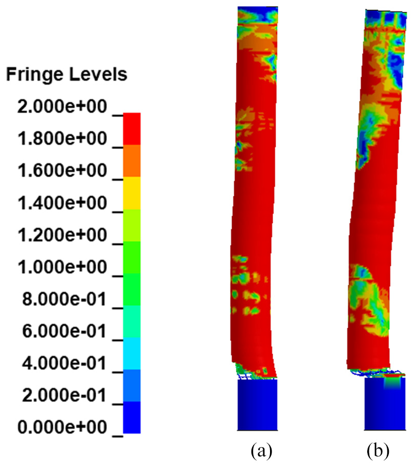
Equivalent plastic damage contour: (a) column without axial load, and (b) column with axial load.
Figure 13(a) presents the axial stress histories of the stirrup located close to the base. It is found that soon after the detonation, the axial stress of stirrups in both columns reaches initial peaks and then drops slightly. After that the axial stress of the stirrup in the column without axial load remains stable while that of the column with axial load has an increase before finally drops back to zero at around 60 ms, indicating rupture of the stirrup. Close examination of the FE model shows that at that time the stirrup breaks due to the axial strain exceeds the limit.
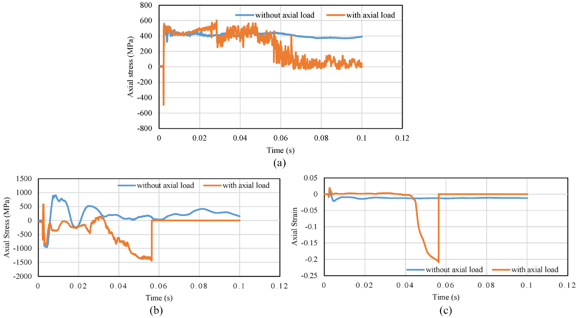
Comparison between simulation results of column with and without axial load: (a) axial stress of stirrup, (b) axial stress of rebar, and (c) axial strain of rebar.
Similarly, the axial stress and strain time histories of longitudinal rebar at column base are shown in Figure 13(b) and (c), respectively. It can be observed that after shear damage occurs, the cross-section capacity deteriorates significantly and axial load on the column induces large axial stress and strain in the longitudinal reinforcements which cause the reinforcement buckling as shown in the simulation. The longitudinal reinforcement of the column with axial load breaks while no breakage occurs in the longitudinal reinforcement of the column without axial load.
Close-in explosion at column mid-span
Figure 14 shows the equivalent plastic damage contours of the columns subjected to close-in explosion at column mid-span. It is easily found that without axial load, the column exhibits slight flexure deformation without severe damage, while with axial load, the column fails because of buckling of longitudinal reinforcements at mid-span owing to the P-delta effect.
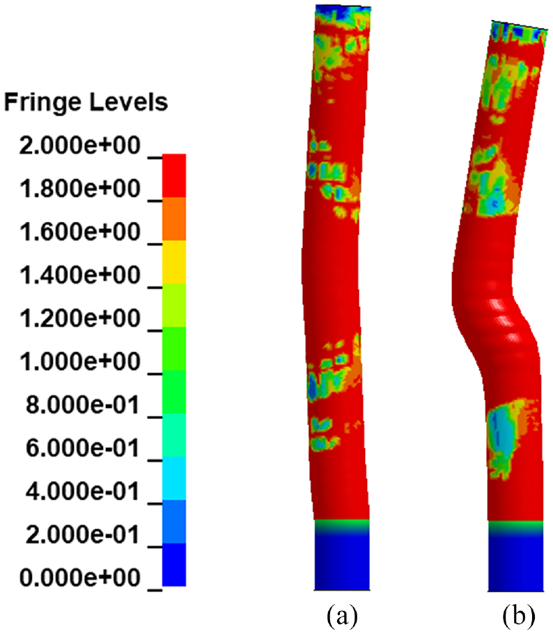
Equivalent plastic damage contour: (a) column without axial load, and (b) column with axial load.
The axial stress of the stirrups at the height of explosion is shown in Figure 15(a). It can be observed that at the very beginning after the detonation, the stirrup axial stresses in both columns are very close, then for the column without axial load, the axial stress value drops slightly and remained stable afterwards. For the column with axial load, the axial stress value keeps increasing until yielding. The high axial stress level in stirrup leads to breakage of the stirrups and buckling of the longitudinal reinforcement as well as the subsequent column failure. The spacing of transverse reinforcement is important for shear resistance and core confinement in the plastic hinge regions of a seismically loaded column. Likewise, blast-loaded columns also require increased transverse reinforcements to ensure ductile behavior.
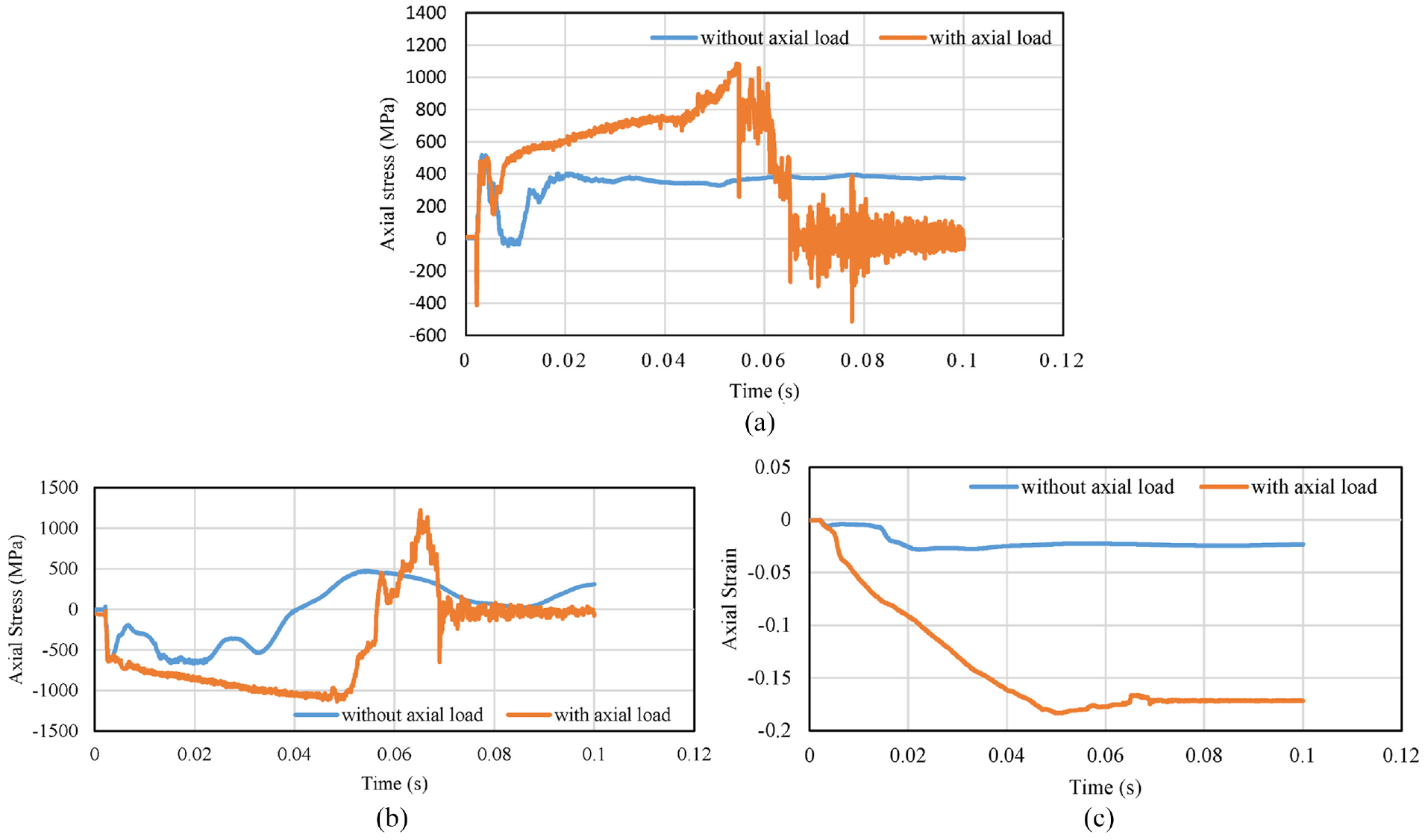
Comparison between simulation results of column with and without axial load: (a) axial stress of stirrups, (b) axial stress of rebar, and (c) axial strain of rebar.
The axial stress and strain histories of rebar at the corresponding location are shown in Figure 15(b) and (c), respectively. It can be observed that both the axial stress and strain of longitudinal reinforcement of the column with axial load are higher than that of the column without axial load, especially the strain. At around 0.07 s, the longitudinal rebar in the column with axial load drops back to zero while its strain remains stable, indicating the reinforcement buckling at column mid-span. It is therefore generally concluded that the dynamic response of bridge column might be underestimated when axial load is not considered in a close-in detonation scenario when large lateral deformation occurs and P-Delta effect is prominent.
Contact detonation
Figure 16 shows the equivalent plastic damage contours of the columns subjected to contact explosion at column mid-span. It can be found that for the column without axial load, there is concrete material failure on the front, side and back face. It is observed that both the side and back face of the column with axial load experienced less damage as compared with the column without axial load. This is because contact detonation induces large stress waves propagating within the column, tensile stress induced by wave reflection at the free surface is responsible for spalling damage of cover concrete. The compressive stress generated by the axial load in the column compensates the tensile stress induced by the stress wave, which enhances the performance of the column subjected to contact explosion. However, as can be noted, although the axial load reduces the cover concrete damage, it causes the buckling of the longitudinal steel reinforcement, while no longitudinal steel reinforcement buckling is observed in the column without axial load. This is because axial load induces axial stress in stirrups and shear stress in the column as discussed above.
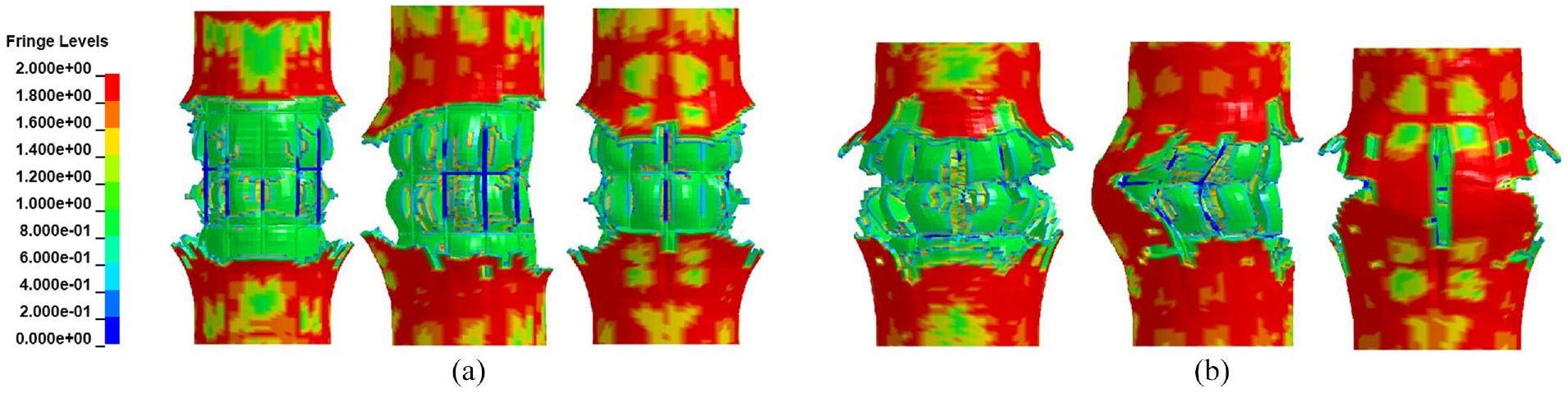
Equivalent plastic damage contour: (a) column without axial load, and (b) column with axial load (for three local damage profiles, the order is front face, side face, and rear face from left to right).
The axial stress of the stirrups at the height of detonation are shown in Figure 17(a). It is observed that at the very beginning of detonation, the axial stresses in the stirrups are similar in the two columns. Without axial loading, the axial stress drops rapidly and remains at a low level while stirrup stress in column with axial load drops slightly and remained at a high level.

Comparison between simulation results of column with and without axial load: (a) comparison of axial stress of stirrups, (b) comparison of axial stress of rebar, and (c) comparison of axial strain of rebar.
The axial stress and strain histories of longitudinal rebar are given in Figure 17(b) and (c), respectively. It is found that axial stress of the longitudinal reinforcement of the column with axial load becomes compressive and grows rapidly, indicating buckling of the longitudinal rebar. Both the axial stress and strain of longitudinal rebar of the column with axial load are higher than those of the column without axial load. Although axial load reduces cover concrete failure, it may cause buckling of reinforcement bars after the failure of cover concrete by stress waves from contact detonation.
Conclusion
In this study, the influences of axial load on the column responses subjected to blast loads were investigated numerically. Far-field, close-in and contact explosion scenarios were considered in the study. The following conclusions were drawn based on the results from the numerical investigation:
When the scaled distance is 0.48 m/kg1/3 with standoff distance of 1.5 m, that is, far-field detonation scenario considered in the study, flexure response mode dominates the column response, the peak displacement of the column without considering axial load is significantly larger than that of the column with axial load, indicating axial load from superstructure can be beneficial to column capacity to resist blast loads.
When the scaled distance is 0.16 m/kg1/3, that is, close-in detonation scenario with standoff distance of 0.5 m, shear failure is the dominant failure mode when detonation occurs on ground surface, the axial load induces higher shear stress at the column base and leads to more severe shear failure of the column. When explosion occurs at mid-span of the column, the column with axial load fails because of buckling of longitudinal reinforcement at mid-span due to the failure of stirrup reinforcements and significant P-delta effect, while the failure of the column without axial load is less severe. These results indicate axial load intensifies the damage degree of the column and should not be neglected in predicting the column responses to blast load from close-in detonations.
For contact detonation, columns with or without considering axial load suffer cover concrete damage, the damage to the side and back concrete cover of the column with axial load is less severe, indicating axial load is helpful to reduce cover concrete damage. However, axial load increases the axial stress in stirrup reinforcements and may cause buckling of the longitudinal steel reinforcements. Therefore, axial load has an important influence on the failure mode of columns subjected to contact detonations and should not be neglected.
The numerical results presented in this study demonstrated that in general, axial load on a RC bridge column is not necessarily beneficial to column resistance to lateral blast load. It is beneficial only when the column response is governed by flexural mode and the deformation is small so that P-delta effect is insignificant. Therefore, it is important to include axial load carried by the column when predicting its responses subjected to blast load. It is noted that the current conclusions are drawn based on the considered column and explosion scenarios, the conclusions are thus limited to the parameters investigated in this study. To derive more general conclusions, further systematic and comprehensive simulations considering more explosion scenarios and column parameters are deemed necessary.
Footnotes
Declaration of conflicting interests
The author(s) declared no potential conflicts of interest with respect to the research, authorship, and/or publication of this article.
Funding
The author(s) disclosed receipt of the following financial support for the research, authorship, and/or publication of this article: This study was jointly supported by the Fundamental Research Funds for the Central Universities, CHD (Grant No. 300102210106) and the National Natural Science Foundation of China (Grant Nos. 52008031 and 51678141).