




Abstract
Conventional co-rotational formulations for geometrically nonlinear analysis are based on the assumption that the finite element is only subjected to nodal loads and as a result, they are not accurate for the elements under distributed member loads. The magnitude and direction of member loads are treated as constant in the global coordinate system, but they are essentially varying in the local coordinate system for the element undergoing a large rigid body rotation, leading to the change of nodal moments at element ends. Thus, there is a need to improve the co-rotational formulations to allow for the effect. This paper proposes a new consistent co-rotational formulation for both Euler-Bernoulli and Timoshenko two-dimensional beam-column elements subjected to distributed member loads. It is found that the equivalent nodal moments are affected by the element geometric change and consequently contribute to a part of geometric stiffness matrix. From this study, the results of both eigenvalue buckling and second-order direct analyses will be significantly improved. Several examples are used to verify the proposed formulation with comparison of the traditional method, which demonstrate the accuracy and reliability of the proposed method in buckling analysis of frame structures under distributed member loads using a single element per member.
Introduction
The total Lagrangian (TL) and updated Lagrangian (UL) formulations based on the Green-Lagrangian strains have been widely used in finite element analysis of geometrically nonlinear structural and solid mechanics problems, which can be found in many textbooks such as Zienkiewicz (2005) and Bathe (2006). The co-rotational (CR) formulation is another well-accepted method (Felippa and Haugen 2005) in nonlinear analysis, especially in frame analysis due to significant simplification of element formulations.
The early geometrically nonlinear analysis procedures were mainly based on TL and UL formulations and directly used the Green-Lagrangian strains to consider large displacements and large rotations, since the nonlinear strains can remove rigid body motions. For example, Bathe and his coworkers (Bathe and Bolourchi 1980; Bathe et al. 1983; Dvorkin and Bathe 1984) proposed geometrically degenerated shell elements using the Green-Lagrangian strains. However, these works are limited to nonlinear small rotations between two load increments, as reported by Surana (1983). He proposed an expression of three-dimensional (3D) large rotations to improve the previous works, but his element formulation should determine the rotation sequence firstly, causing inconvenient in practical applications.
How to deal with 3D large rotations in geometrically nonlinear finite element method attracted considerable research interest such that numerous different expressions have been proposed. One of the most accepted methods was introduced by Argyris (1982). His work is based on Euler theorem and still often used in the studies of geometrically nonlinear elements, for example, the work by Jeon (2015).
All these mentioned geometrically nonlinear elements are mainly derived using total displacement functions and the Green-Lagrangian strains, while the pertaining analysis algorithms are mainly conducted in the fixed global coordinate system. Thus, their displacement functions and element formulations are very complicated, especially when an expression of 3D large rotation is used.
The co-rotational concept can be integrated with the TL and UL formulations, in which the total motions of an element are divided into the rigid body part and the pure deformational part by attaching a local coordinate system to the element. Only the pure deformational motions, which can be described by the local element formulation, produce strain energy. In this analysis procedure, formulations are established in the local element system firstly and then transformed into the global coordinate system. Thus, the co-rotational TL and UL formulations are simpler than the general formulations mentioned before. For example, Hsiao (1987) and Hsiao and Hung (1989) proposed geometrically nonlinear shell elements based on co-rotational TL and UL formulations, in which a co-rotational procedure is used to eliminate the rigid body motions and get the element internal nodal forces. Yang and Chiou (1987) proposed a rigid body motion test to verify whether a finite element can be used in a geometrically nonlinear analysis, and this test is consistent with the co-rotational concept. The other applications of the co-rotational TL and UL formulations can be found in the works by Tang et al. (2016), Jiang et al. (1994), and Khosravi et al. (2007, 2008).
The co-rotational (CR) formulation discussed in this paper is also called the element independent co-rotational (EICR) formulation which was firstly introduced by Rankin and Brogan (1986). This kind of formulations is derived through establishing the relationship between local and global coordinate systems. Thus, this CR formulation has an explicit geometric stiffness matrix expressed with end nodal forces rather than stresses at the integration points for TL and UL formulations. This feature leads to a unified geometric stiffness matrix for the elements having the same nodes and degrees of freedom. For this reason, this co-rotational formulation is element-independent. Moreover, the material nonlinearity can be simply considered in the local element formulation with significant enhancement of numerical efficiency.
A strict EICR formulation for 3D finite elements is also very complicated, in which the changes in element dimensions, the rigid body rotations of the element and the non-commutative nature of 3D large rotations should be considered in the derivation (Battini 2002; Crisfield 1990; Nour-Omid and Rankin 1991; Skallerud and Haugen 1999). In addition, the tangent stiffness and the internal forces are strictly consistent since the tangent stiffness is derived through the partial differentiation of the internal forces. To simplify EICR formulations, some simplified methods were proposed and still have good performance with high accuracy and efficiency. For example, Tang et al. (2017) neglected the changes in element dimensions and significantly simplified the EICR formulation for shell elements; Izzuddin (2005) proposed a co-rotational method for shell elements without removing rigid body motion completely. This method was further improved by Izzuddin and Liang (2016) and Li et al. (2017, 2018).
Before the introduction of EICR formulation by Rankin and Brogan (1986), a simplified EICR formulation had been used in the geometrically nonlinear analysis of frames, such as in the work by Meek and Tan (1983). Their CR formulation has been extensively used in the derivation of nonlinear beam-column elements (Chan and Zhou 1994, 1995; Du et al. 2017; Tang et al. 2015, 2019). Compared with the conventional TL and UL formulations, the most prominent advantage of the EICR formulation is that some complicated beam-column elements allowing for local second-order effect can be readily extended into the analyses of large displacements and large rotations.
It should be pointed out that the previous EICR formulations assumed that the applied loads are nodal. This assumption is valid for the geometrically nonlinear analysis of structures subjected to constant distributed loads without significant geometric change. However, it is not reasonable for the case when the element is undergoing large rotations. To solve this problem, the traditional methods should use several elements per member. It is no doubt that the computational time will be significantly increased. It will also bring problem in modeling of member geometrical imperfection using one element per member. Thus, the changes of the equivalent nodal moments should be considered in the exact CR formulation. Note that the distributed member load is not only due to the self-weight of structural element but also those from non-structural elements such as claddings, liquid in pipe, ice loading, and so on. It is worth to propose a method to improve the accuracy of EICR formulations for nonlinear analysis.
In this paper, a new co-rotational framework is proposed, which is suitable for both Euler-Bernoulli and Timoshenko beam-column elements. The 2D problem is studied here for clear illustration of the proposed method. First, the CR formulation for 2D beam-column elements only subjected to nodal forces are introduced and its physical meanings are discussed. After that, the exact CR formulation for beam-column elements under distributed member loads is derived. The local beam-column elements under distributed load according to both Euler-Bernoulli and Timoshenko beam theories will be introduced. Finally, several numerical examples are presented to illustrate the accuracy and efficiency of the present study.
Co-rotational beam-column element under member loads
Unlike the traditional co-rotational formulation for beam-column elements which only consider the nodal loads at element ends, the distributed member loads are taken into account in this paper.
Figure 1 shows the deformations of the beam-column element in the global coordinate system (o g x g y g ), in which the member load is assumed as the uniformly distributed load. The local coordinate system (oxy) moving with the beam-column element is defined by the two end nodes, dividing the element total motions into two parts, that is, rigid body movement and pure deformation. The magnitude (p) and the direction (−y g ) of the distributed member load defined in the global coordinate system remain unchanged after the element deforms, but they are varying in the local coordinate system as the element deflects.

Co-rotational beam-column element under member load.
As shown in Figure 1, the beam-column element moves from the initial position to the current position with the global displacement vector
Then, the pure deformations produced in the local frame (oxy) can be given by
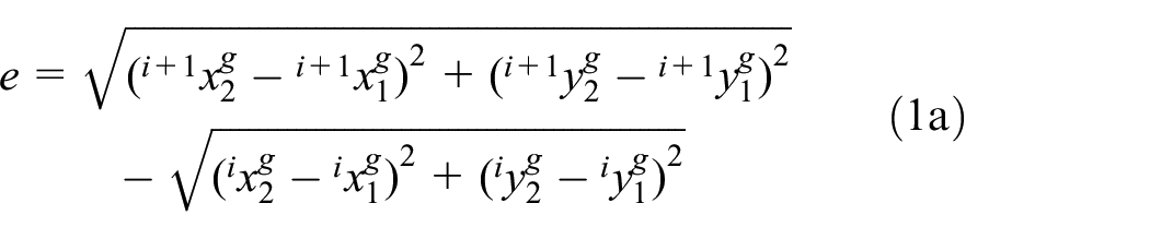




where
By taking a variation of equation (1), the relation between the virtual pure deformations and the virtual global displacements is

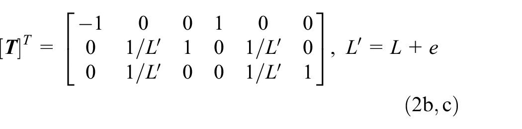


in which
Nodal applied loads
When the external loads only contain nodal loads at the element ends, the relation between the basic and global force vectors can be derived through the principle of virtual work as follows


The previous derivation is the traditional element-independent co-rotational formulation for 2D beam-column element with only considering nodal loads. The basic to local transformation matrix [
In fact, the force relation between basic and global systems in equation (3b) can be given directly through force equilibrium equations, in which the physical interpretation of the transformation from basic to local plays an important role. Specifically, the basic forces
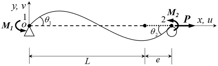
Basic beam-column element with a simple support.
Distributed applied member loads
To derive the exact co-rotational formulation for beam-column elements under distributed member loads, we can resort to the force equilibrium equations and the physical interpretation introduced in the last subsection. Figure 3 shows the beam-column element under nodal and distributed member loads in the basic system.
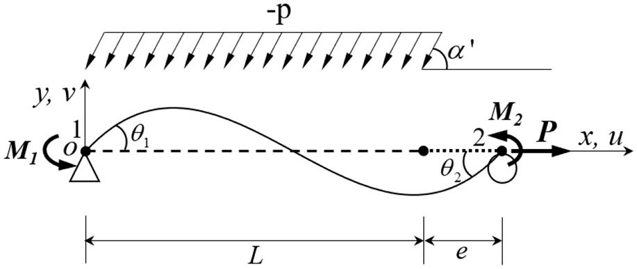
Beam-column element under distributed load.
In this system, the beam-column element is derived based on the total Lagrangian description. Then, the total potential energy functional Π, which is the sum of strain energy U, work done by nodal forces Wf, and work done by gravity load Wp, can be given by



in which
By taking the first variation of the total potential energy functional in equation (4a), it is easy to get the nodal forces in the basic system as follows

where
It can be seen from equation (4c) that
Local beam-column element formulations
Several local beam-column elements considering distributed loads and containing the loads in the displacement or force interpolation functions have been proposed by some researchers. For example, Zhou and Chan (1997) proposed an effective element for second-order analysis of steel frame allowing for axial and lateral distributed loads, while the local second-order effect was considered at the same time. Also, the family of flexibility-based beam-column elements (Du et al., 2017; Neuenhofer and Filippou, 1997, 1998) are able to consider the distributed loads in the force fields or stress resultants.
This paper mainly focuses on the co-rotational formulation rather than the local elements. To illustrate the present study clearly, the proposed element is assumed as prismatic and elastic and neglects the warping and the local second-order effect. Then, based on the classical beam-column element with linear axial and cubic transverse displacement interpolations, the uniformly distributed load is exactly considered in the displacement functions herein.
To consider the distributed loads, the axial and transverse displacement interpolations in the basic system are assumed as quadric and quartic functions respectively in the following


As the local second-order effect is neglected, the axial and bending parts of the element are not coupled and then can be treated separately in the derivation. With respect to the axial part of the element, the pertaining equilibrium differential equation and the boundary conditions can be given by


Through equations (7) and (6a), the coefficients ai in equation (6a) can be solved and then the expression of the axial displacement function is given by

In terms of the bending part of the element, two different beam elements based on Euler-Bernoulli and Timoshenko beam theories are studied respectively, by using the quartic displacement function in equation (6b).
Euler-Bernoulli beam theory
According to Euler-Bernoulli beam theory, the relation between rotation and transverse displacement at arbitrary point x of the beam is given by

Then, the equilibrium differential equation of the beam under uniformly distributed load can be derived as follows

where Q and M are the shear force and moment of the beam element, respectively.
Also, the boundary conditions of the beam element are


in which E is the elastic Young’s modulus, A is the cross-sectional area, and I is the second moment of area.
Substituting equations (10) and (11) into equation (6b), the coefficients bi can be solved and then the expression of the transverse displacement function is derived out in the following

Also, based on Euler-Bernoulli beam theory, the strain energy of the beam-column element can be given by

Through equations (4), (5), (8), (12), and (13), the nodal forces due to strain energy and the equivalent nodal forces of the uniformly distributed load in the basic system can be derived out and given by
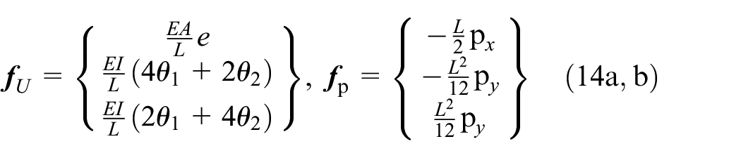
Then, the material stiffness matrix of the beam-column element in the basic system is


Timoshenko beam theory
Based on Timoshenko beam theory, the transverse shear strain γ and the curvature κ can be given by

Besides, the equilibrium differential equations of Timoshenko beam are


in which k is the sectional shear correction factor and G is the shear modulus of elasticity.
Through these equations and the boundary conditions given in equation (11), the expression of transverse displacement and rotation can be obtained as follows
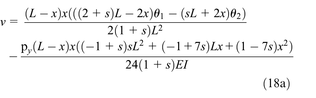
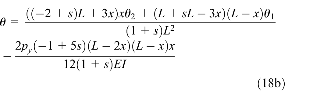
in which
The strain energy of the beam-column element based on Timoshenko beam theory is
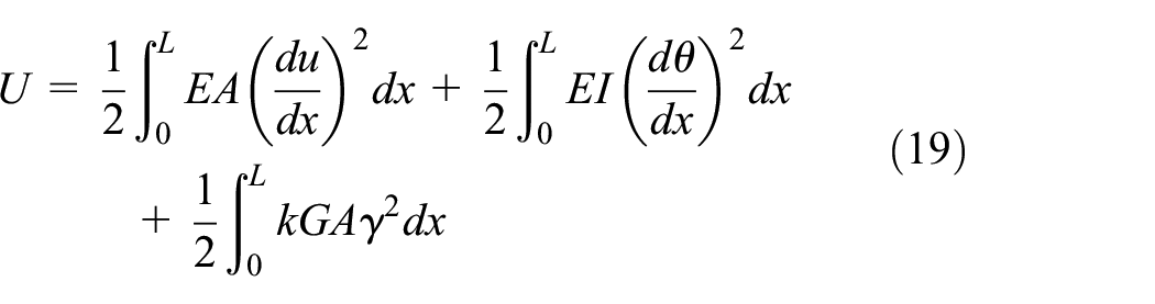
Following the derivation presented in the last subsection, the nodal forces due to strain energy and equivalent nodal forces of the uniformly distributed load in the basic system become
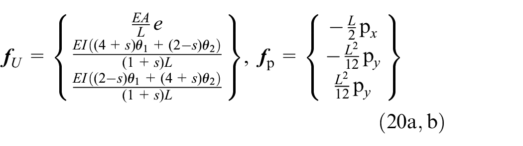
The effect of the transverse shear deformation is considered in


Transformation from basic to global systems
In the last section, the nodal force vectors of the beam-column element in the basic system based on Euler-Bernoulli and Timoshenko beam theories have been presented, respectively. To derive the exact co-rotational formulation of the beam-column element, the relation between basic and global systems, which is involved with two transformations, should be established.
The first transformation of the nodal forces is from basic to local systems. As pointed out in Section 2, it is a procedure to extend three element qualities into six qualities and remove the element constraints. In addition, the change in element length should be considered in this transformation. Thus, the nodal forces in the local system can be given by


in which the transformation matrix [
Meanwhile, the equivalent nodal forces of distributed member load in the basic system after element deformation are


in which the variables with a symbol “′” on the right side means that they belong to the current element configuration.
Assuming that the distributed member load is gravity, we have

The second transformation of the nodal forces is from local to global systems. The global nodal forces of the element can be expressed as

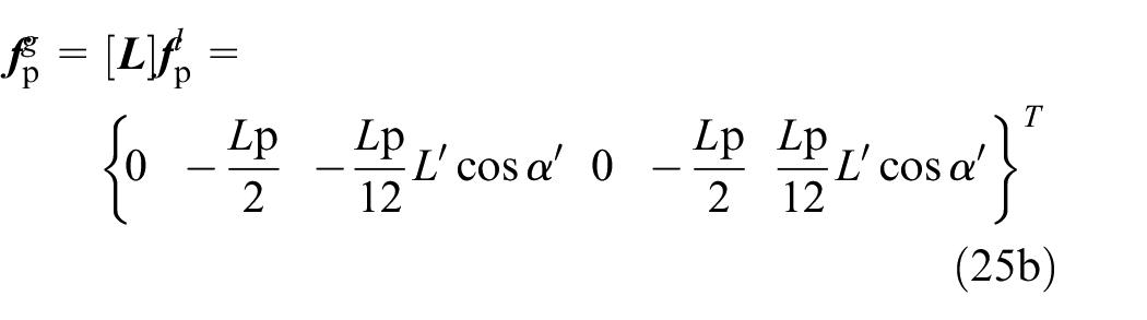
If the equivalent nodal forces of the gravity load,
Then, by taking a variation of equation (25a), we have
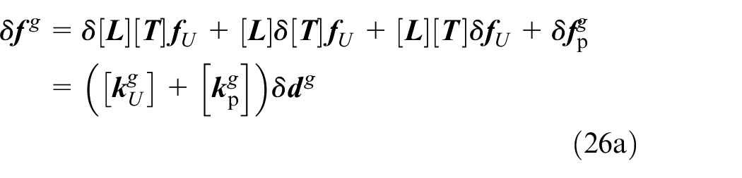


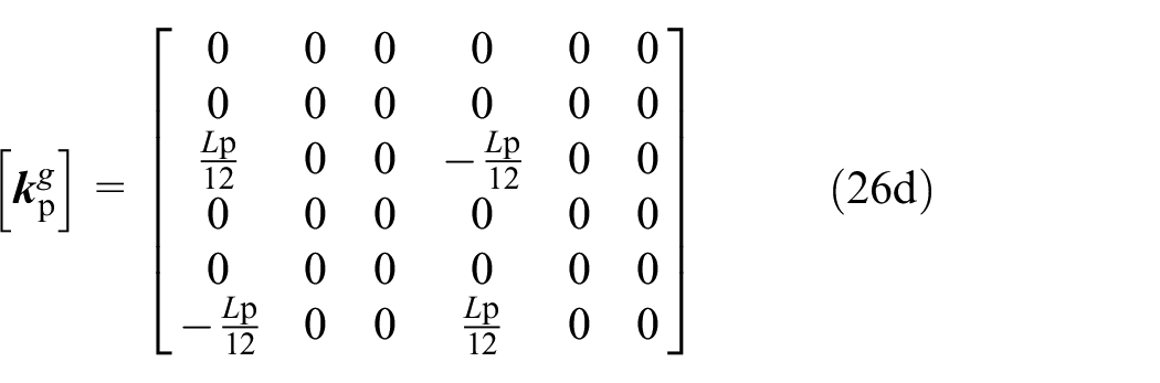
It can be seen that the global tangent stiffness matrix has two parts. The matrix
Numerical examples
To verify the accuracy and efficiency of the proposed exact co-rotational formulation for beam-column elements under distributed member loads, several numerical examples are presented in the section. From the last section, the expressions of
To validate the proposed co-rotational formulation, the traditional method to deal with member loads is also investigated in these examples, which adopts the equivalent nodal loads of the member load computed according to the initial configuration of structure and omits their variations due to the large rigid body rotations. The global nodal forces due to member load in equation (25b) are constant in the whole analysis procedure and given by

There is no doubt that the pertaining tangent stiffness matrix due to the gravity load,
Besides the geometrically nonlinear analyses, the eigenvalue buckling analyses for Examples 1 and 3 are also presented. The eigenvalue problem is generally expressed as

where
Example 1: Column under gravity load
As shown in Figure 4, a simple column under gravity load and horizontal concentrated load at the top is used to test the proposed co-rotational formulation in the large deflection analysis. In this example, the column is 100 cm in length (L), 1 cm2 in area (A), 1 cm4 in second moment of area (I), and 2 × 10⁷ N/cm2 in elastic Young’s modulus. The maximum values of the horizontal concentrated load and the pressure due to gravity load are 100 N and 300 N/cm, respectively, while this study does not consider the load applied sequence and therefore these loads are applied simultaneously to the column. Also, it should be noted that the concentrated force at the top is small and produces small deflection when it is applied on the column independently, with the purpose to initiate imperfection and sideway of the column.
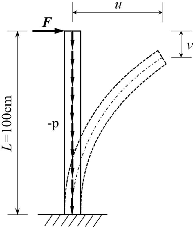
Column under gravity load.
The column is modeled by 1, 2, and 4 beam-column elements and then solved by the presented co-rotational method and the traditional load method, respectively. The results obtained by these different methods are plotted in Figure 5. As shown in Figure 5, the results of the present study are in good agreement with the traditional method when the column is modeled with four elements and can be regarded as reference solutions. For the column model with two elements, the results of both two methods are close to the reference solutions. However, significant differences between these two methods arise for the column using a single element, and it can be seen that the present study is evidently better than the traditional load method.
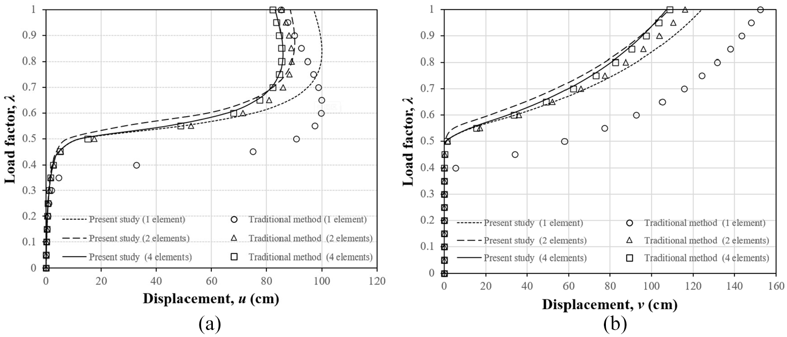
Load versus displacement curves for cantilever column: (a) Load vs. displacement u, and (b) Load vs. displacement v.
The results of the eigenvalue buckling analyses by different models are provided in Table 1 which shows that the proposed formulation is more accurate than the traditional method when only one element per member is used.
Results of eigenvalue buckling analyses for Example 1.
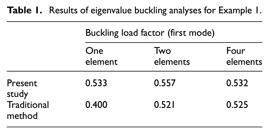
It can be seen that the one-element model using the present method can accurately predict the buckling load, though its results of nonlinear analysis gradually deviate from the reference solutions in post-buckling stage as the local linear beam-column element is limited to small local pure deformations. This problem can be improved by using higher performance beam-column elements allowing for large deformations. Regarding the one-element column model using the traditional load method, the results are far away from the reference solutions. This is because the equivalent moments are neglected according to the initial vertical configuration, which in fact arise after deformation and help the column against buckling. In this example, the advantage of the proposed co-rotational formulation for beam-column elements under gravity load is remarkable.
Example 2: Cantilever beam under gravity load
A cantilever beam under gravity load, which is a classic example for checking the capability of an element undergoing large displacements and large rotations, is shown in Figure 6. This model adopts the same geometric and material properties as those in Example 5.1. Different from the last problem of a column, there is no buckling behavior in this example and the gravity load is mainly resisted by the bending stiffness of the cantilever beam.
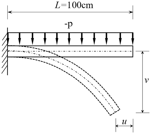
Cantilever beam under gravity load.
Following the last example, different numbers of beam-column elements and geometrically nonlinear analysis formulations are used to simulate the cantilever beam under gravity load. The results obtained from these methods are plotted in Figure 7. In addition, the horizontal and vertical displacements corresponding to the gravity load p of 400 N/cm are listed in Table. 2.
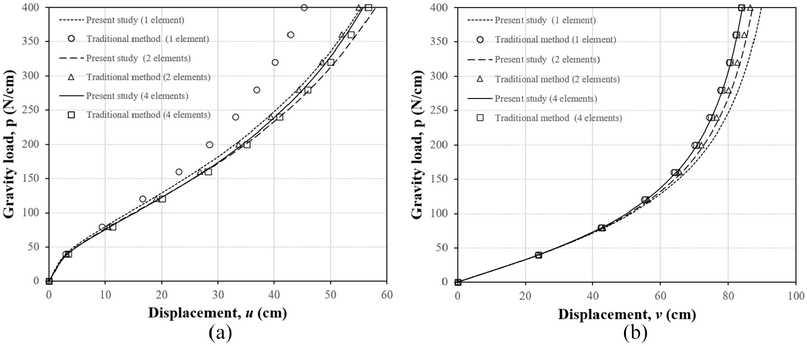
Load versus displacement curves for cantilever beam: (a) Load vs. displacement u, and (b) Load vs. displacement v.
Numerical results for cantilever beam with p = 400 N/cm.

The performance of the present study and the traditional method are similar to the last example. The differences between the results obtained from these methods decrease with the increasing number of elements, while the present study is still better than the traditional load method when only one beam-column element is used to simulate this example. For the one-element model, the discrepancy of the present study comes from the local beam-column element, which could be reduced by considering the local second-order effect in the element formulation, such as the element proposed by Tang et al. (2015). In general, compared with the traditional method, the improvement of the presented co-rotational formulation under gravity load is also significant.
Example 3: Three-story frame under gravity load
The three-story frame shown in Figure 8 is investigated in this example. All members of this frame adopt the same square cross-section with 1 cm2 in area (A) and 0.0833 cm4 in second moment of area (I), while their material properties are the same as those in the last two examples. The notional force

Three-story frame under gravity load.
Similar to the first example, the notional force

Load versus displacement curves for three-story frame: (a) Load vs. horizontal displacement u, and (b) Load vs. vertical displacement -v.
Results of eigenvalue buckling analyses for Example 3.
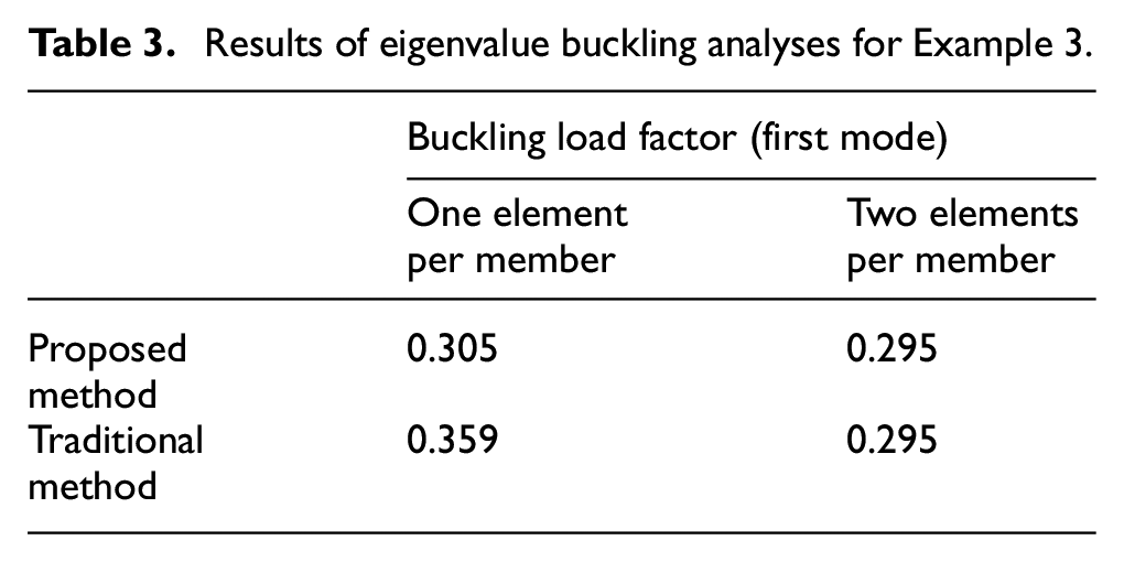
It can be seen from Figure 9 and Table 3 that the results of the present study and the traditional method agree well with each other when each frame member is divided into two elements. In terms of the models of one element per member, the results given by the present study are close to those by the two-elements per member models. It demonstrates that the proposed method is better than the traditional one.
Example 4: Plastic analysis for three-story frame under gravity load
The three-story frame presented in Example 3 is also used here to illustrate the performance of the proposed method considering material yielding by plastic hinge method. The yield stress of the material is assumed as 23,500 N/cm2 and the elastic-perfectly plastic model is adopted in the plastic hinge method. The influence of axial force to the full yield surface is also neglected herein since it is small compared to the end moments. The plastic moment capacity of all members is 5875 N cm. Once the bending moment is larger than the plastic moment, a plastic hinge will form at the member end. The well-known arc-length method for nonlinear solution is used to trace the full load-displacement curve.
The horizontal displacements u at Point A of the three-story frame are plotted in Figure 10. It shows that the results obtained from the proposed method using one element per member is more accurate than the traditional method. The deviation compared to the models using two elements per member is due to that the local beam-column element formulation is based on the assumption of small strains without consideration of local second-order effect. This example clearly shows the advantage of the proposed co-rotational framework. To demonstrate the merit of the proposed method, only the conventional beam-column elements are used for easy comparison. To increase the analysis accuracy, more complicated second-order beam-column elements can be introduced.
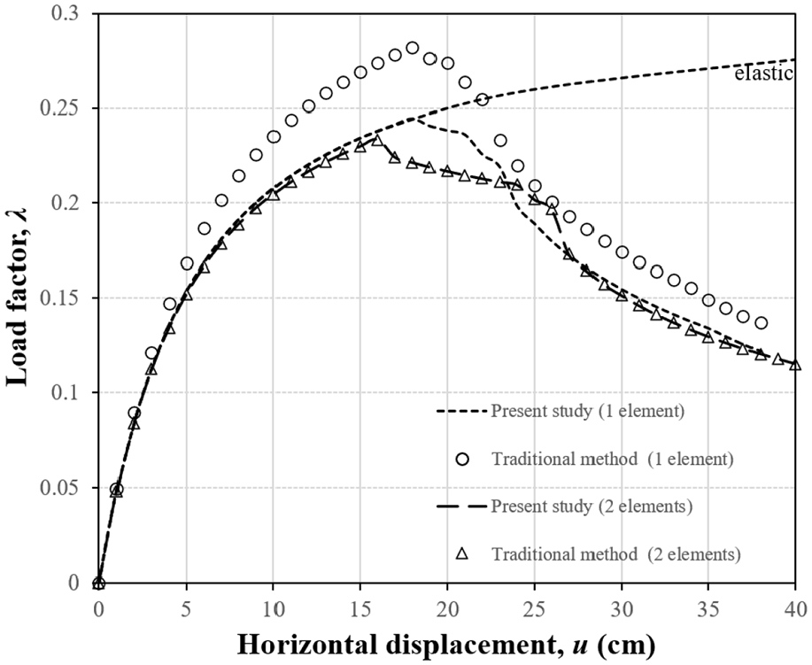
Load versus displacement curves for three-story frame.
Conclusion
The conventional co-rotational formulation adopted in eigenvalue buckling and second-order direct analyses cannot accurately consider the distributed member loads, especially for member undergoing large rotations. In this paper, an exact and consistent co-rotational formulation is first proposed for both Euler-Bernoulli and Timoshenko beam-column elements under distributed member loads. This work will significantly improve the accuracy and reliability of the commonly used structural buckling methods in practical applications. Several examples have been used to verify the accuracy of the proposed method. By contrast, the traditional method cannot consider the variations of the equivalent nodal moments due to large rotations. From this study, the following conclusions can be made:
Several elements per member are required for the structures subjected to distributed member loads undergoing large rotations when using conventional co-rotational formulations.
The element independent co-rotational (EICR) method provides a unified approach for buckling analysis using both Euler-Bernoulli and Timoshenko beam-column elements.
The proposed new co-rotational formulation significantly improve the accuracy of both eigenvalue buckling and second-order direct analyses.
It should be pointed out that this paper mainly focuses on the co-rotational framework. To predict the nonlinear behaviors more accurate, more advanced local element including initial member imperfections should be used. For practical application of the proposed method, the co-rotational formulations for 3D beam-column elements will be presented in our future work.
Footnotes
Authors’ Note
Yao-Peng Liu is also affiliated with NIDA Technology Company Limited, Hong Kong Science Park, Shatin, N.T., Hong Kong, China.
Declaration of conflicting interests
The author(s) declared no potential conflicts of interest with respect to the research, authorship, and/or publication of this article.
Funding
The author(s) disclosed receipt of the following financial support for the research, authorship, and/or publication of this article: The authors are grateful for financial support from the Research Grant Council of the Hong Kong SAR Government on the project “Second-order analysis and design of scaffolds with scissor braces and allowing for kink imperfections (PolyU).” The first author is also grateful for the financially supported by the National Natural Science Foundation of China (52008094) and Natural Science Foundation of Jiangsu Province (SBK20200402).
