



Abstract
To improve the mechanical performances of joints in prefabricated construction, a type of connection structure with long-fiber and metal laminated bolts (referred to as a fiber-metal connector) is proposed and investigated by simulation and theoretical methods. The results include the following: (1) The fiber layer in bolts can form a second stiffness during rotation. This mechanical characteristic improves the bearing capacities and energy dissipation ability of the connector relative to the conventional metal connector, which are expected to effectively limit the elastoplastic rotational displacement of a structure. (2) For the reason, the fiber layer can bear load in the plastic phase due to its high-strength characteristic in the length direction. (3) A bilinear model for the bearing curve of the fiber-metal connector is proposed, and equations for optimization of fiber layer thickness are obtained with a target on bearing capacity and energy dissipation ability which are approximately higher 30% and 13% than that of the conventional metal connector, respectively. This research is expected to provide a theoretical basis for the application of this fiber-metal connector in engineering and improve the safety of prefabricated structures.
Introduction
Construction engineering, especially that of buildings (Collinge et al., 2013; Ünay and Özmen, 2006), continues to support human life and production. Generally, cast-in-place and assembly methods are widely used (Mushinskiy et al., 2015; Okumus and Oliva, 2015). Among them, the most common method is the cast-in-place method, especially in developing countries, where raw materials are easily accessed, the associated costs are lower, and this approach has been proven. However, in recent years, many countries and regions have gradually reduced the use of this construction method due to noticeable disadvantages (Abey 2019; Koyankin and Mitasov, 2015), such as a low production efficiency, waste of resources, long construction periods, and vulnerability to weather. As another option, prefabricated structures are preferred in shortening the construction period, reducing environmental pollution, reducing material consumption, complying with green construction, and following the principles of sustainable development (Alimoradi, 2015; Liu et al., 2019b; Pongiglione and Calderini, 2016).
However, the components should be transported to the site and be connected after being prefabricated in a factory, the strength and stiffness of the connectors have essential effects on the force transmission and bearing, deformation and energy consumption of the overall structure (Chen et al., 2019; Smith et al., 2014; Zhang et al., 2020). Therefore, the performance of connectors has become a critical factor in determining the performance of prefabricated structures. Compared with the cast-in-place structure, the integrity of the prefabricated structure is weaker, generally resulting in larger deformation, especially under a seismic load that produces an enormous amount of energy. Nevertheless, according to previous studies, using connector deformation to absorb energy is one of the important ways to improve the safety and reliability of prefabricated structures.
For example, Xiao et al. (2015) launched a comparative experiment of seismic behavior between cast-in-place and precast frames, which shows that the precast frame has inferior behavior due to the post-cast joint. A new type of dapped-end beam-to-column connection was proposed by Liu et al. (2019), in which the connection was relocated from inside to the midspan of the beam for better internal force redistribution and energy dissipation capacity. Zhang et al. (2017) proposed a new prefabricated sinusoidal corrugated web beam-column joint, which effectively transfers the bending moment and shear force. Maya et al. (2013) designed a frame connector connected by ultrahigh-performance reinforced concrete. Yuan et al. (2019) investigated the improvement in ECC material (a fiber-based engineering cement composite material) with excellent energy consumption ability. Nakaki and Robert (1994) embedded a high ductility alloy connecting rod in a column as a connector, and a precast beam was connected to the precast column by bolts. Cheng et al. (2015) found that the use of high-strength bolt connections can achieve the same stiffness and energy consumption as cast-in-place connectors. Oh et al. (2009) designed a slotted steel plate damper that could be replaced in a rigid connector and showed that the damper had excellent hysteresis performance. Wu et al. (2015) proposed a sector lead viscoelastic damper connector for a prefabricated frame structure. The results showed that the total energy consumption was twice that of ordinary prefabricated connectors. Wang (2016) used a pin and connecting plate to form a hinge at a beam end; after that, Sun (2018) improved Wang’s connector and achieved the elastic deformation of prefabricated beams and columns with a plastic damper. Although the above research improves the energy consumption of a connector and a joint, once the plastic state is reached, the rotation deformation of the connector is hard to be controlled due to the mechanical characteristics of the metal and concrete (generally, metal yielding at 200–400 MPa and concrete cracking at tens of megapascals). As a result, the possibility of buildings deflecting or even being damaged due to excessive connector rotation significantly increases.
Recently, fiber composite materials have become increasingly and widely used in many fields, including civil engineering (Allam, 2019; Chen et al., 2018; Feng et al., 2019; Silva and Gamage, 2020; Wang et al., 2019; Zhang et al., 2016), which have several or even dozens of times the tensile strength in the fiber length direction and are regarded as in an elastic state until reaching their tensile strength. In detail, Wang et al (2019) investigated the fatigue degradation and life prediction of basalt fiber-reinforced polymer (BFRP) composites after saltwater corrosion and its application in long-span cable-stayed bridges (Feng et al., 2019). Chen et al. reported that a bionic sandwich plate based on BFRP composite materials with short fibers can achieve better mechanical properties in bending (Zhang et al., 2016) and shear forces (Chen et al., 2018). Silva and Gamage (2020) explored the use of carbon fiber-reinforced polymer (CFRP) in dowels on flat slabs, which is an effective way to enhance both punching shear capacity and flexural capacity. Some scholars also used fiber materials to improve the seismic performance of connectors. For example, Kim (2013) invented glass fiber-reinforced polymer sheets with clip connectors, indicating several improvements in column seismic performance with the strengthened group. Allam (2019) proposed a composite system using high-strength CFRP laminate and a hybrid composite connector to enhance the rebar bond slippage and shear strength.
However, the above-mentioned excessive rotational deformation of connectors in the plastic stage has involved little study. To solve this problem and further improve the energy dissipation ability, the present work proposes a new type of connector with long-fiber and metal laminated bolts (referred to as a fiber-metal connector) (Zhang et al., 2016) for prefabricated building structures. Furthermore, simulation and a theoretical method are used to investigate its mechanical properties and conduct a comparison with a conventional metal connector. These results are expected to provide a theoretical basis for the application of this fiber-metal connector in engineering and an inspiration for improving the safety of prefabricated structures.
Modeling design and finite element analysis
Modeling design
The connector with fiber-metal laminated bolts is placed between the beam and column in this study, whose position are shown in Figure 1(a). An entire connector consists of gusset plates (A and B), a pin (C), and fiber-metal laminated bolts (D). The dimensions of each part are shown in Figure 1(b)–(d). For the gusset plates (A, consisting of three steel plates; B, consisting of two steel plates), the height is 300 mm (Figure 1(b)), the width is 250 mm (Figure 1(c)), the thickness is 20 mm (Figure 1(b) and (c)). The end distance (de) and axis distance (da) between two adjacent steel plates are 30 and 50 mm. For the pin (C), the dimensions are 250 mm in length and 50 mm in radius (Figure 1(c)). The key part for the connector is the bolt (D), which is 250 mm in length, 30 mm in width, and 9.5 mm in height (Figure 1(b)–(d)). It is formed with laminated metal and fiber layers, including five layers of metal and four layers of fiber in this model (Figure 1(d)).
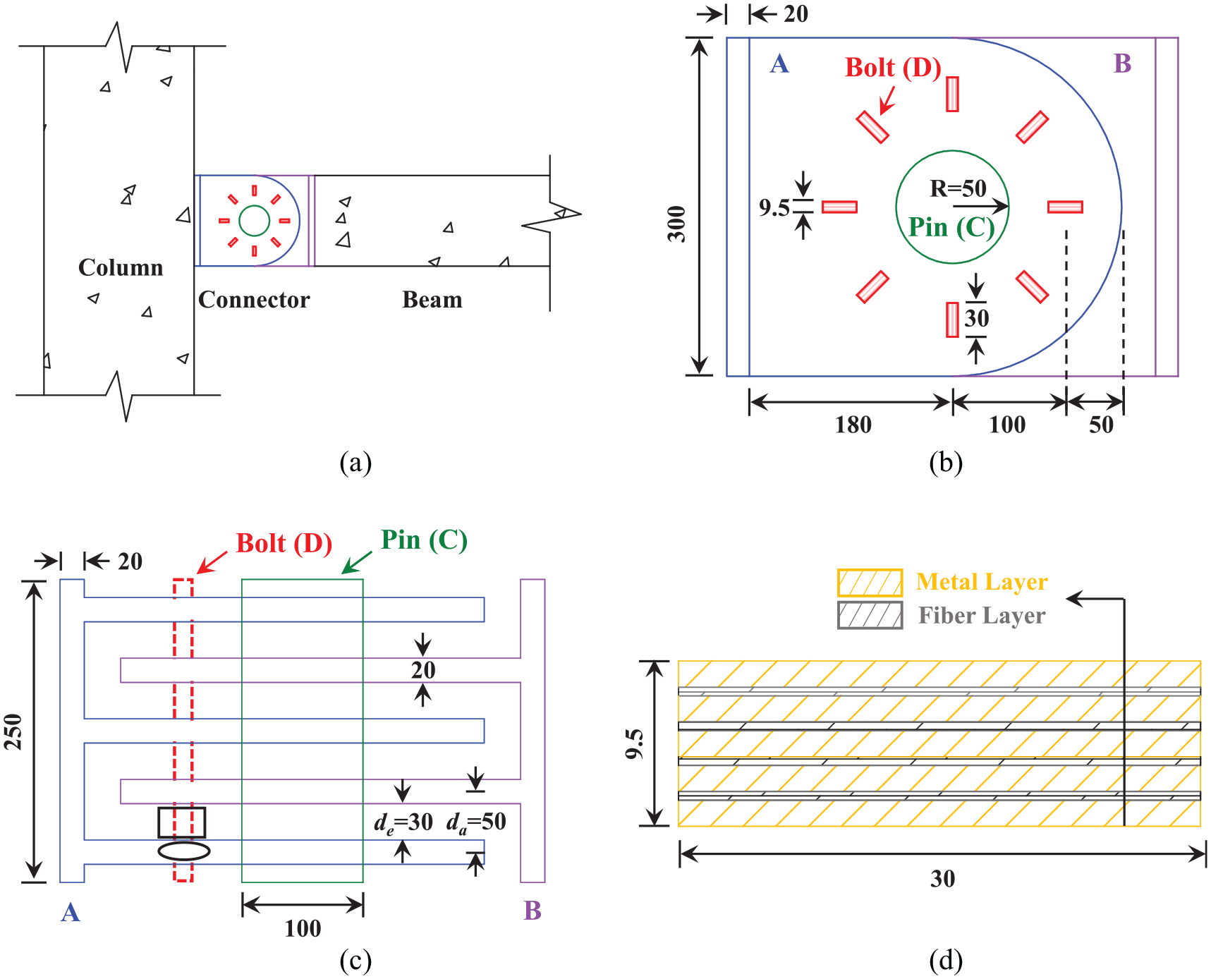
Model and dimensions of the fiber-metal connector and its components: (a) the position of the connector; the model and dimensions, side view (b) and top view (c, for convenient observation, only one bolt is shown); (d) the laminated fiber-mental bolt, side view. All dimensions are shown with a unit, mm.
On this basis, to investigate the influence of the thickness and types of fiber layers on the mechanical performance of the proposed connector, there are four fiber-metal connectors in total with different types of fiber layers and dimensions. In the first group, basalt fiber layers are used in the bolt, and the thicknesses are 0.500 and 1.056 mm, respectively; the bolt of the second group uses a carbon fiber layer; similarly, the thicknesses of the fiber layer are 0.500 and 1.056 mm, respectively. Meanwhile, to better explain and compare the mechanical properties of fiber-metal connectors, this study uses a traditional connector with the bolts made only of metal without fibers. All connectors have the same overall and detailed dimensions, except for the material composition and layer thickness in the bolt, which are summarized in Table 1.
Summary information of the five connector models.

Finite element method (FEM)
To study the mechanical properties of fiber-metal connectors and the differences from conventional metal connectors, this study uses ABAQUS 2018 to develop a finite element analysis. In practical engineering, these two gusset plates would both generate rotations. However, according to the principles of strong columns and weak beams and relativity motion, to simplify the analysis, the present study assumes that the gusset plate (A) connected to the column is set as fixed, and only the rotation load is applied on the gusset plate (B) that is connected to the beam, as shown in Figure 2.

The boundary condition, loading scheme, and contact definition in the FE modeling.
The two gusset plates (A and B) use C3D10 solid elements, and the number and size of elements are approximately 100,000 and 7.5 mm, respectively. The pin (C) is inserted using C3D8R solid elements, and the number and size of elements are approximately 5000 and 8 mm, respectively. The bolt (D) uses C3D8R elements. For the metal bolt in the conventional connector, the number and size of elements are approximately 40,000 and 1.2 mm, respectively. For the fiber-metal laminated bolt, the number and size of elements for each single-layer fiber are approximately 7500 and 1 mm, while those for each single-layer metal are approximately 2000 and 2 mm, respectively. According to the rotational movement of the connector and mechanical principle, there are three type of contacts defined as follows.
1) The interface between the fiber and metal layers in a bolt
Regardless of the slip between the fiber layer and the metal layer, a tie constraint is used between these layers, where the metal surface is the main surface, and the fiber surface is the secondary surface.
2) The interface between the bolt and steel plate
To ensure the load transfer, according to the rotation direction set for gusset plate B in Figure 2, the gusset plate B rotates clockwise. In this case, taking bolt 1 as an example, its lower face tends to be compressive by the steel plate, which means that there is a close contact between the bolt and steel plate. Thus, the tie constraint is set in their interface. However, the upper face tends to separate from the steel plate when the gusset plate rotates, so there would be a small gap between the bolt and steel plate; thus, no constraint is set for this interface.
3) The interface between the cylinder pin and the gusset plate
The cylinder pin (C) and gusset plates (A and B) are in surface-to-surface contact, whose tangential behavior is determined by the contact with a friction coefficient of 0.2. Their normal contact uses a hard contact and can be separated.
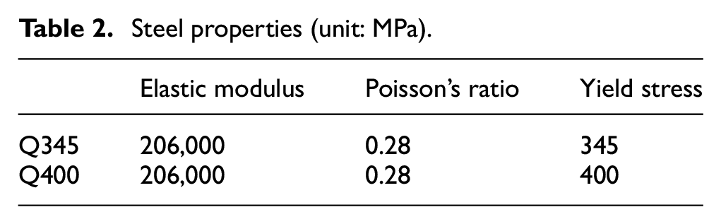
In terms of the materials for each component, the gusset plates and the pin are made of Q400 steel (GB50017-2017, 2017) (the material properties are shown in Table 2). Since the pin serves only as a rotation axis, the pin is not considered to reach the plastic state in this model. The metal layer in the bolt uses Q345 steel (GB50017-2017, 2017), and its properties are shown in Table 2. The fiber layer can be made of several fiber cloths adhered to each other by epoxy resin and adhered to the metal layer by epoxy resin as well. Thus, the fiber layers have greater tensile strength only in the tensile direction, and both compressive and shear strength can be regarded as provided by the epoxy resin. Their detailed mechanical properties are shown in Table 3 (GB50608-2010, 2010).
Steel properties (unit: MPa).
Properties of fiber layer (unit: MPa).

Results and discussion
Mechanical property of the fiber-metal connector
According to the finite element analysis, the rotation-moment curve (or bearing curve) of the fiber-metal and conventional metal connectors are obtained, as shown in Figure 3. Different countries and regions, especially in seismic areas, have set rotational displacement limitations (the ratio of the relative horizontal displacement between two adjacent floors to their height) for various building structures in the design code. For example, according to the Chinese Code of Seismic Design of Buildings GB 50011-2010 (2010), for a frame structure, the maximum rotational displacement limitation in the elastic range is 1/550, and that in the elastoplastic stage displacement is 1/50. Therefore, the mechanical properties of the fiber-metal connector are discussed based on this rule in the present study; subsequently, the above curve is divided into three zones (I, II, and III): (i) Zone I refers to the structural deformation within the elastic limitation; (ii) Zone II refers to the structural deformation in the limitation of the elastoplastic range; and (iii) Zone III refers to the deformation over the elastoplastic limitation, which should be avoided as much as possible in practical engineering.
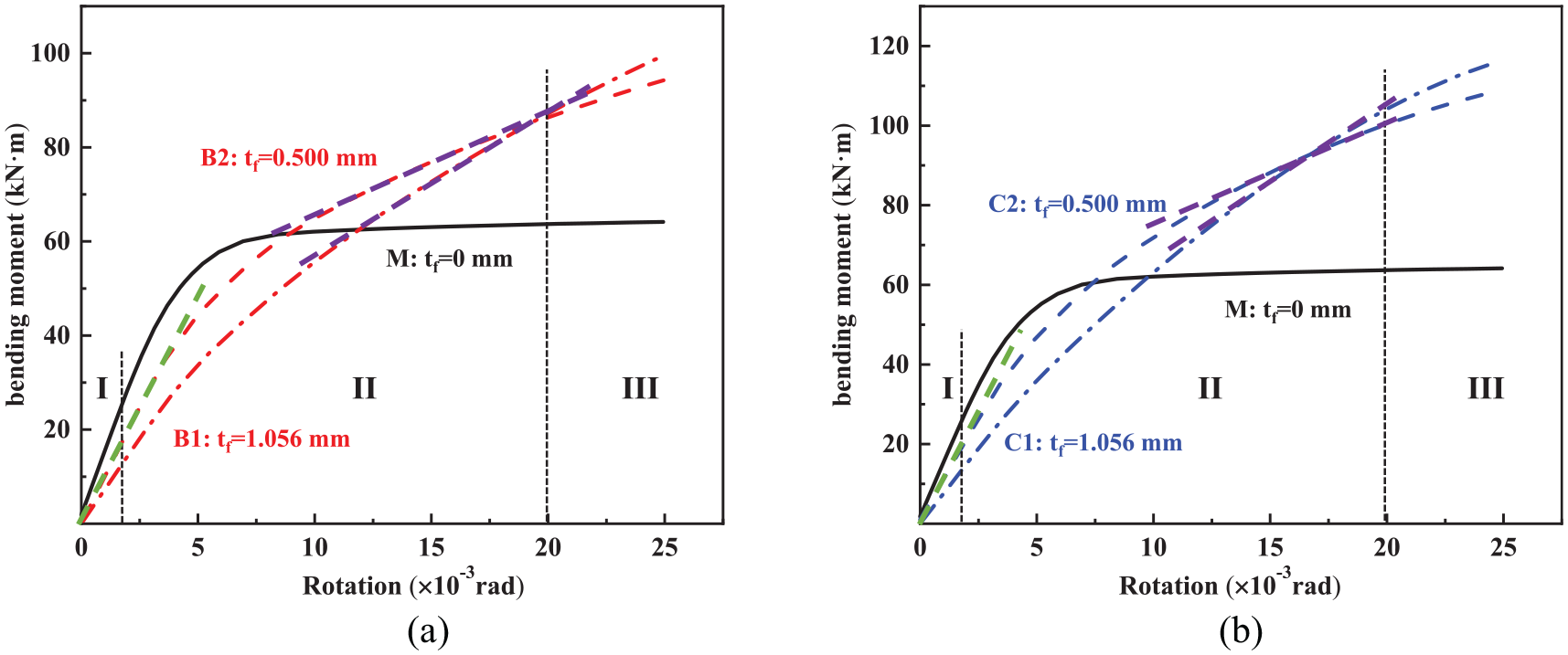
Rotation-bending moment curves: (a) connector with basalt fiber layer and (b) connector with carbon fiber layer. The meaning of M, B, C can be found in Table 1; tf refers to the thickness of the fiber layer.
From Figure 3, for the rotational stiffness of the fiber-metal connector in the elastic range (Zone I, referred to as the elastic stiffness), its value is the slope of the straight line at the beginning of the bending moment-rotation curve (green dashed line), and it is lower than that of the metal connector. Considering that the building structure itself, such as beam-column joints, possesses a certain lateral stiffness, which should be able to resist these small lateral actions caused by small earthquakes or wind loads in the elastic range according to the common structural design code. Therefore, it would have little influence on the mechanical performance of a structure.
However, in the design of modern structures, especially for high-rise buildings or buildings in seismic areas, the plasticity stage (Zone II) is of prime essence and significance. In this case, especially after a rotation of approximately 0.0075 rad, the bearing capacity of the metal connector hardly increases (Figure 3). Although many studies have suggested that the connector can absorb a large amount of seismic energy in this stage (Smith et al., 2014; Xiao et al., 2015; Zhang et al., 2020), their rotation displacements are difficult to be controlled effectively in this stage; thus, the excessively large rotation would cause an obviously increase in the possibility of damage to the connectors or structures. In contrast, the curve of the fiber-metal connector generates a secondary stiffness, the ability to resist the rotation of the connector in the elastoplastic stage (Figure 3, Zone II, purple dashed line), causing a significant increase in bending capacity relative to the conventional connector, which could be used to effectively limit the elastoplastic rotational displacement. Taking the B1 model (basalt fiber with a thickness of 0.5 mm) as an example, when the load reaches approximately 63
To further analyze the mechanical properties, Figure 4 shows the elasticity and secondary stiffness, bearing capacity, and energy dissipation capacity for different fiber types (basalt and carbon fiber) and thicknesses (0.500 and 1.056 mm). From Figure 4 (a), when the thickness of the fiber layer in the bolt is 0.5 mm (models B1 and C1), the elastic stiffness of the two fiber-metal connectors decreases by 20%–25%, and the decrement of the connector with carbon fiber is 3.4% less than that of the basalt-fiber connector. However, the secondary stiffness of the fiber-metal connector formed during the plastic stage is 1400%–1500% higher than that of the traditional counterpart, and that of the carbon fiber connector is also larger (Figure 4(b)), which makes its bearing capacity 57.4% higher relative to that of the metal connector (Figure 4(c)) when their rotation reaches the limitation of elastoplastic deformation. For the energy dissipation capacity, weaker improvement is achieved in the fiber-metal connector for B1, C1, and C2, as shown in Figure 4(d), which means that, with reasonable fiber type and thickness, it can be controlled to be better than that of the conventional connector.
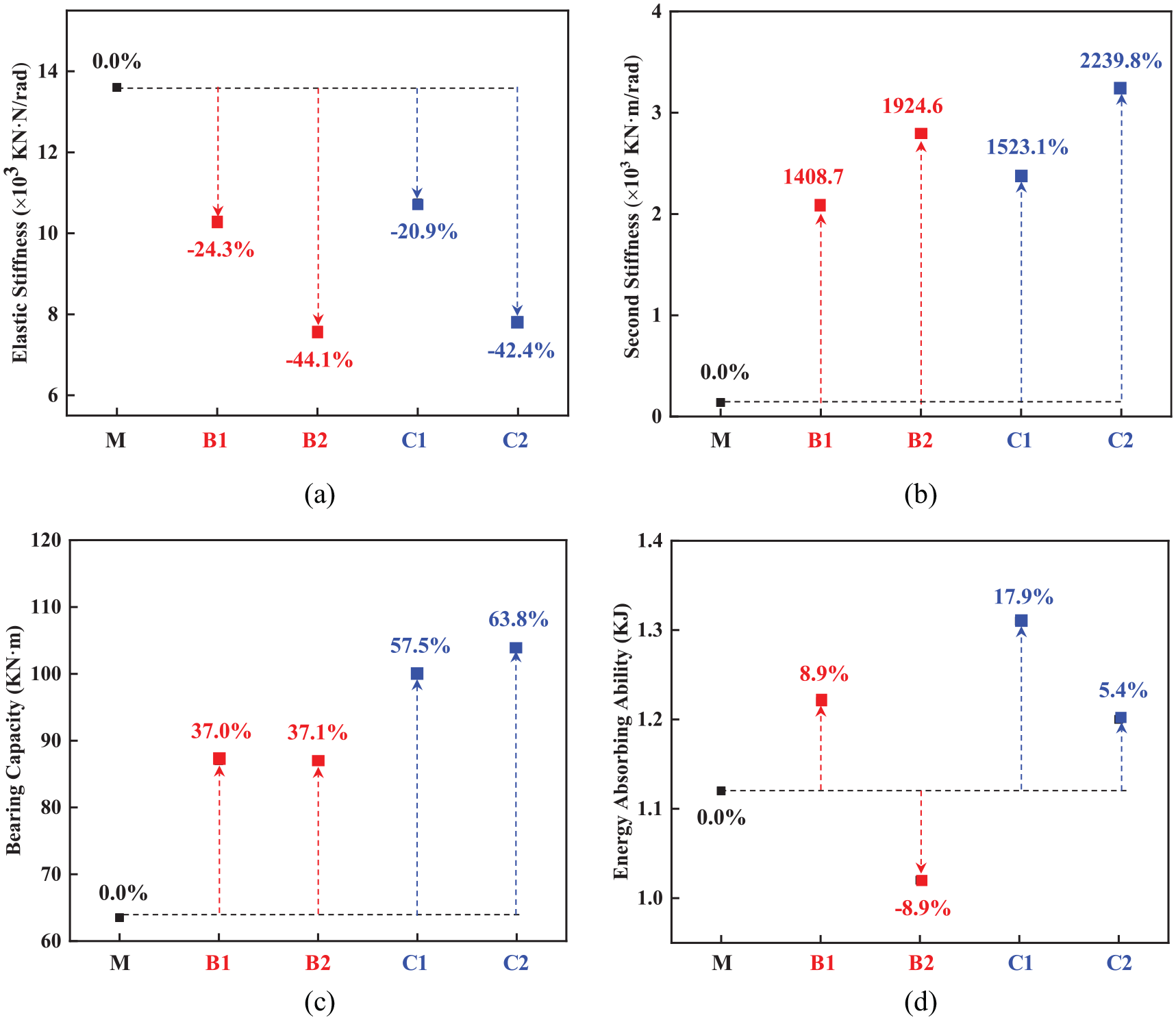
The influence of the type and thickness of the fiber layer on (a) the elastic stiffness, (b) second stiffness, (c) bearing capacity, and (d) energy absorbing ability of the connector. Among them, the second stiffness in (b) is the average slope of a relatively stable part of each curve near the elastoplastic rotational displacement limitation, marked by the purple dashed line in Figure 3; the values in (c) and (d) are adopted and calculated based on the elastoplastic deformation limitation value (0.02 rad).
Therefore, to achieve the optimal bearing capacity and energy dissipation ability with reasonable thickness of the fiber layer of the proposed connector, the role of the fiber and the corresponding mechanical mechanism during the rotation process are illustrated below.
Mechanical mechanism of the metal-fiber connector
The only difference between these connectors is the bolt structure. As shown in Figure 1, the bolt is continuous and connected to the steel plates. Therefore, it is assumed that the bolt is fixed at both ends while allowing translational displacement. Figure 5 shows a schematic diagram of the force and deformation of the metal-fiber laminated bolt in the elastic (Figure 3, zone I) and plastic ranges (Figure 3, zone II). Because the gusset plate A has three steel plates and gusset plate B has two steel plates, which means that there are four same gaps between these steel plates, as shown in Figure 1. Therefore, 1/4 structure of a bolt is used in Figure 5 for simplification.
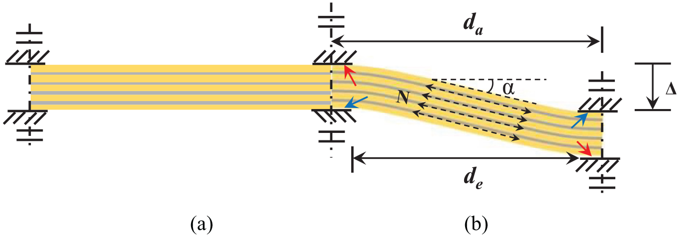
Schematic diagram of the deformation of the metal-fiber laminated bolt in the elastic (a) and plastic (b) ranges.
The fiber layer has relatively high elastic modulus only along its length, while relatively lower modulus in shear, causing a degradation of elastic stiffness for the fiber-metal connector. However, when the connector enters the plastic stage, the metal yields rapidly; the fibers have several times the tensile strength and are still in an elastic state. In addition, the deformation of the bolt in the elastic stage is considerably small, and its dimensions can be assumed to be constant during a mechanical analysis (Figure 5(a)). However, in the plastic stage, the bolt deformation is much larger, and an obvious inclination angle (α) is generated, as shown in Figure 5(b). Therefore, two obvious extra bending moments should be considered. First, there is an obvious axial force N in the fiber layer, and due to the influence of the inclination angle (α), a component force is generated to continuously resist the rotation of the connector. Second, the fiber layer is in the elastic state, and the load can be further increased. Because carbon fiber has a higher elastic modulus and tensile strength, its secondary stiffness is also greater.
Therefore, the bearing capacity and the energy dissipation ability of the connector can be improved by forming the secondary stiffness of the rotation-bending moment curve because the fiber has high-strength tensile properties and can exert this feature when the bolt enters the plastic stage. Subsequently, a bilinear model of the rotation-bending moment curve of the fiber-metal connector and its calculation method are proposed in next section; furthermore, an emendation and optimization analysis are carried out to achieve better mechanical performances.
The bilinear model of the bending capacity curve for the fiber-metal connector and its calculation method
The bilinear model of the bearing curve for the fiber-metal connector is shown in Figure 6, which can be determined by Me and Mu, which refer to the elastic bending capacity and ultimate bending capacity (corresponding to plastic displacement limitation) of the connector, respectively. Considering that, the increment from Me to Mu refers to the extra bending resistance generated by plastic deformation of the bolt; Me and this increment will be calculated to perform the theoretical analysis, emendation and optimization based on the bilinear model of the fiber-metal connector.

The bilinear mode of the bearing curve of the fiber-metal connector.
Elastic stiffness and bending capacity of the fiber-metal connector
Elastic stiffness of the fiber-metal connector
In the present model, a connector has eight bolting parts. As described in Section 3.2 and Figure 5, each bolt is equivalent to the 1/4 structure according to the symmetry. The displacement generated by a unit force is the flexibility (δ), which is the backward count of the deformation stiffness. Considering the difference in material properties of metal and fiber, it is supposed that the elastic stiffness consists only of contributions from metal.
Due to the difference in constraint setting of two interfaces between the bolt and steel plates mentioned in Section 2.2 (2), for the bending deformation, there is a gap between unconstraint interface of the bolt and steel plate according to the deformation trend of the bolt, as shown in the Figure 5, red arrows. Therefore, the equivalent length of bending is supposed as the distance between the central axis of two adjacent steel plates, namely da. Subsequently, the bending flexibility of the bolt is:


where,
b: the width of the bolt;
h: the height of the bolt;
da: the equivalent length for bending, which is 50 mm in the present model;
E: the elastic modulus of the metal;
For shear, according to the deformation trend of the bolt, the equivalent length is supposed as the end distance between these two steel plates, namely de, as shown in the Figure 5, blue arrows, because there are tie constraints in these two interfaces. Subsequently, the shear flexibility of the bolt is:

where,
de: the equivalent length for shear deformation, which is 30 mm in the present model;
v: Poisson’s ratio of the material;
A: the cross-sectional area of the bolt in the metal connector;
τ: the shear stress;

Subsequently, the elastic stiffness of Zone I of the bilinear model is:

where,
n: 1/n of the symmetrical structure is considered, where n is 4 in this model;
N: the number of fiber-metal laminated bolts, which is 8 in this model;
R: the distance from the center of the bolt to the center of rotation, which is 100 mm in this model;
Elastic bending capacity of the fiber-metal connector
According to Figure 3, the bearing curve of the fiber-metal connector has a transition process between the elastic and second stiffness, which means that the bolt is transferring from elastic to plastic. However, in the bilinear model, only a point, A, is between these two stages. Therefore, to simplify the calculation, it is supposed that Point A refers to where the middle cross section of the upper part of the bold yields, namely the middle cross section of the second metal layer, as show in Figure 7, red dotted line.
a) Bending of metal layer
Based on the material mechanism, the bending moments of a bolt caused by metal layers are:


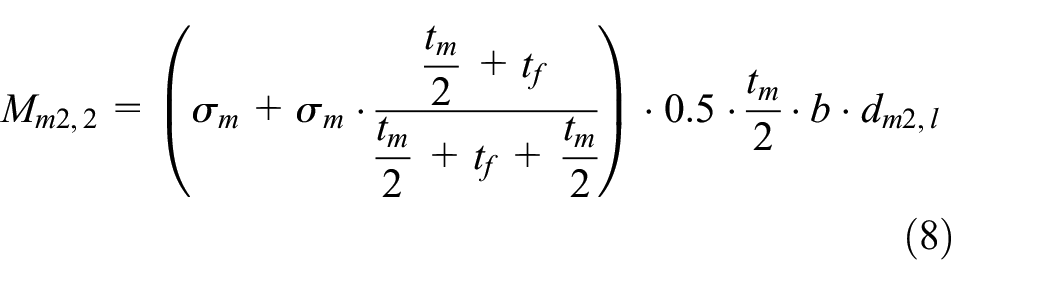
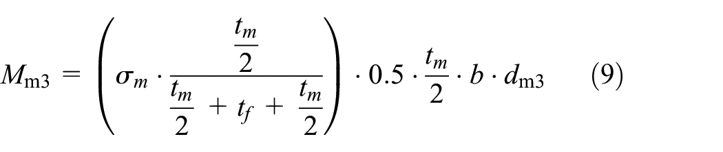
where,
σm: the yielding strength of the metal;
dmi: the distance from the central axis of the ith layer fiber to the central axis of the bolt;
Mmi: the bending contribution from the ith layer metal to the bolt;
Mm2, u and Mm2, l : the bending contribution from the upper and lower parts of the second metal layer of the bolt, respectively;
dm2, u and dm2, l : the distances from the central axis of the upper and lower parts of the second metal fiber to the central axis of the bolt, respectively.

The mechanical analysis model of the equivalent model of a bolt. The mechanical analysis of an equivalent model with a unit force f = 1 N (a, b); the cross section of a bolt (c).
Therefore, the deformation stiffness of the 1/4 bolt is.
Therefore, the bending moment from the metal layers to a bolt in Zone I is:

The force produced by this moment and perpendicular to the bold is:

b) Shear of metal layer
When the middle of the metal layer yields, the bending moment in the bolt should be:

The shear force in the bolt is:

where da is used here because the shear force is caused by the bending moment of the metal layer.
Therefore, the elastic bending capacity of the fiber-metal connector, namely, the vertical coordinates of Point A in Figure 6 is:

The abscissa of Point A can be calculated by combining equations (5) and (14):

The increased bending capacity in the plastic stage
Contribution from the fiber layer
As mentioned above, the shear modulus of the fiber layer is weak, and the bending capacity of the fiber-metal connector does not include the shear of the fiber layer while including the following two parts.
a) Bending of fiber layer
In the plastic stage, the fiber layers undergo large deformation, but they remain in the elastic stage due to the high elastic modulus. Therefore, their strain relationship is still regarded as linear, as shown in Figure 8(a) and (b). In the finite element simulation, the elasticity of the fiber layer in the length direction is the same in tension and compression.

Strain analysis of the bolt in the plastic stage: (a) cross section of the fiber-metal bolt and (b) the strain state.
For the fiber layer, the strain from the ith layer fiber (Figure 8) is:

where dfi is the distance from the central axis of the ith layer fiber to the central axis of the bolt.
The bending moment formed in the upper part of the fiber layer is:

where tfi refers to the thickness of the ith fiber layer.
The force produced by the fiber layer perpendicular to the bolt is:

In formula (17), εfi is unknown. Therefore, the relationship between ε and θ is solved below. When in the elastic range, the following equations are defined for the bending deformation of the bolt as a beam:


Thus, ε and F are linear. Considering that f and Δ, as well as Δ and θ, have a linear relation, ε and θ also have a linear relation. When in the plastic stage, in the above relationships, only F and δ are no longer linear. However, this nonlinearity is supposed to be caused by the yielding of the metal materials; that is, it belongs to the material nonlinearity. For the geometric relationship between ε and θ, this paper still assumes that it is linear; that is, the rotation angle θ is taken as the control factor, and a certain rotation angle causes the equivalent structure to produce a certain strain;

Therefore, according to the mechanics of materials (Liu, 2010), for the bolt strain status at Point A, its strain in the middle cross section of the bolt is:

Then:

where,
σ m refers to the maximum stress of metal;
Em refers to the elastic modulus of metal;
Subsequently, for the fiber layer, when the rotational displacement of the connector reaches the limitation, 0.02 rad, its strain can be expressed by:


b) Stretch of fiber layer
In the elastic stage, the lateral deformation of the bolt can be regarded as horizontal, as shown in Figure 5(a), because the elastic deformation is relatively small. However, in the plastic stage (II), the lateral deformation of the bolt is more obvious and inclined (Figure 5(b)). There is an axial force N that acts in the bolt, and under the influence of the inclination angle α, the component force is generated:

where,



Therefore, the increment bending moment in Zone II from the fiber layers is:

Contribution from the metal layer
a) Shear of metal layer
According to the assumption in Section 3.3.1.2, when the bending moment reaches Point A, the first metal layer has already yielded and formed the plastic hinge. Therefore, after Point A, the displacement of the connector is supposed to be undertaken by the bending deformation of the bolt. Therefore, in the plastic stage (Zone II), the shear deformation of the metal layers does not form extra bending capacity to the whole connector.
b) Bending of metal layer
In the plastic stage, the metal layers yield totally. Subtracting the bending moment formed in Zone I, its extra bending moment in the bolt is:

The force produced by the fiber layer perpendicular to the bolt is:

c) Stretch of metal layer
Similar to the fiber layer, when the whole bolt is inclined, there is an axial force N that acts in the bolt:

Therefore, the increment (extra) bending moment in Zone II coming from metal layers is:

Therefore, the increment (extra) moment in Zone II is:

The abscissa coordinate of Point B is 0.02, and the vertical coordinate is:

Subsequently, the energy dissipation ability of this fiber-metal connector is:

The validation for the bilinear model and the optimization for mechanical performances of the fiber-metal connector
Models C1 and C2 (carbon fiber, the thickness of each single fiber is 0.5 and 1.056 mm, respectively) are used as examples to validate the analytical solution. For model C1, the analytical values of the bending capacity and energy consumption based on the bilinear model are 96
To be validated by the finite element results, the fiber layer is supposed to be in a tensile-compressive isotropic state in the previous step. However, the compression property of the fiber layer itself is generally much weaker than that of tensile. If it is regarded as zero for simplification, the bending moment cannot be formed in the fiber layer, but a component force Ff1,II′ is generated under the influence of the inclination angle α; thus,

Therefore, in the calculation process, equation (18) should be substituted with equation (38). With this modification, when the thickness of the fiber layer set as 0.34 mm, better mechanical performances in both bearing capacity and energy dissipation ability can be achieved relative to the conventional connector, which is an improvement of approximate 30% and 13%, respectively.
Notably the compressive performance of the fiber layer is totally ignored in the modification. However, it should not be zero because of the binder, such as resin, and the radial compression caused by adjacent metal layers. Therefore, the mechanical performances are expected to be higher than the prediction.
Conclusion
To further improve the mechanical properties and safety of prefabricated structures, a new type of connector structure with fiber-metal laminated bolts is proposed in the present study. The finite element method and theoretical calculations are used to study its mechanical performance, calculation method and optimization.
The results show that the fiber layer has high elastic strength only in the length direction, so it has difficulty functioning in the elastic phase. This results in the connector’s elastic stiffness being lower than that of a traditional metal connector. However, when the fiber-metal connector transitions into the plastic phase, the metal layer has yielded, and the high-strength tensile property of the fiber layer allows it to remain in an elastic state. This mechanism forms the second bending stiffness and improves the bearing and energy dissipation capacities, which effectively limits the elastoplastic rotational displacement of a structure compared with the conventional metal connector.
Furthermore, a bilinear bearing model is proposed to calculate the mechanical performance, which has been verified by FEM results. The single-layer fiber thickness is used as an independent variable for optimization; the calculation results show that when the thickness of the fiber layer is 0.34 mm, the bearing and energy dissipation capacity are approximately improved by 30% and 13%, respectively, relative to traditional connector.
Therefore, the present study can provide a theoretical basis for the application of this fiber-metal connector in engineering. However, as the first study, it lacks more practical considerations, such as the potential compression performance of the fiber layer mentioned above, and the optimization in fiber properties, such as the use of fiber with higher elastic modulus and ductility. Therefore, in the future, manufacturing technologies and experiments will be explored. As the key factor, the material properties of fiber will be subjected to systematic research.
Footnotes
Author’s note
Sujun Guan is now affiliated with Bio-Nano Electronics Research Centre, Toyo University, Saitama, Japan.
Declaration of conflicting interests
The author(s) declared no potential conflicts of interest with respect to the research, authorship, and/or publication of this article.
Funding
The author(s) disclosed receipt of the following financial support for the research, authorship, and/or publication of this article: The work was financially supported by the National Key R&D Program of China under project 2017YFC 0703700.
