



Abstract
This paper presents an experimental study on shear strengthening of reinforced concrete (RC) deep beams using externally applied carbon fiber reinforced polymer (CFRP) jackets. A total of 18 RC deep beams were tested using a four-point bending load. The examined parameter included span to depth ratio with or without CFRP strengthening. CFRP strips were applied perpendicular to the probable crack pattern as observed during testing for un-strengthened beams. The properties that is cracking behavior, ultimate strength, deflection, and energy dissipation capacity of beams were evaluated and discussed. The test results showed enhancement in shear strength up to 17% with CFRP. An increase in depth of RC deep beams caused a decrease in the rate of enhancement in shear strength for CFRP strengthened beams as compared to that observed in their counterparts. The experimental test results were compared with the existing design guidelines to assess their application for RC deep beams strengthened with CFRP. A strength equation based on regression analysis was developed to predict the experimental shear strength of RC deep beams strengthened with CFRP. This study showed that the RC deep beams strengthened with CFRP can effectively be used in structural engineering applications with enhanced shear strength and energy absorption capacity.
Keywords
Introduction
Adverse performance of reinforced concrete (RC) structures is being observed due to several reasons which may include an increase in designed load, modification in structure, and errors in design. Two different ways of dealing with such structures are rebuilding or strengthening. The rebuilding of a structure may be uneconomical and time-consuming in some cases. This leads to an option of strengthening of structure that may be more desirable. Moreover, the strengthening of existing concrete buildings has become more practicable during the last two decades.
Many conventional strengthening techniques have been used in the past for repairing, retrofitting, and rehabilitation of concrete structures, such as steel plates, external post-tensioning, externally bonded fiber-reinforced polymer (FRP), sprayed concrete and ferrocement, and near-surface-mounted FRP systems. Numerous studies have been conducted in the past to evaluate the effectiveness of strengthening techniques. Roberts and Haji-Kazemi (1989) strengthened RC beams with externally applied steel plate to the tension face and a significant increase in stiffness was observed.
Belal et al. (2015) used a steel jacketing technique and observed that the size of the batten plates had a significant effect on the failure load for RC columns strengthened with angles. Babaeidarabad et al. (2014) investigated the feasibility of fabric-reinforced cementitious matrix (FRCM) materials as an alternative external strengthening technique for RC members. The FRCM is a composite material consisting of one or more layers of a cement-based matrix reinforced with dry-fiber fabric. Experimental results showed that the FRCM had improved the flexural capacity of RC members. Strengthening with sprayed concrete was experimentally studied by Diab (1998). The Ferrocement technique in strengthening was introduced in 1987 and was further developed and investigated by numerous researchers. However, surface preparation is a big challenge for the above-mentioned technique (Adhikary et al., 2000). A significant increase in deadweight and size limitations of strengthened members is also the major drawback associated with these techniques. Debonding was also observed with the use of steel plates for the strengthening of the existing RC structures (Oehlers, 2001). Proper anchorages were considered to be an additional essential element to overcome the de-bonding issues (Jones et al., 1988).
The fiber-reinforced polymer (FRP) is an effective strengthening material because of its performance in the areas of strengthening, repairing, and retrofitting concrete structures (440 AC, 1996; Cabral-Fonseca et al., 2018; Dalalbashi et al., 2012; Eslami et al., 2019, 2020; Eslami and Ronagh, 2013; Fukuyama et al., 1997; Mukhtar and Faysal, 2018; Ramezanpour et al., 2018; Wan et al., 2018). FRP system can significantly improve the overall performance of the structure if the stiffness is not a major concern. Strengthening with carbon fiber reinforced polymer (CFRP) may overcome most of the drawbacks of the above-mentioned techniques and materials. As compared to other strengthening materials, CFRP possesses numerous advantages which include weather-resistant, durable, and provides ease in installation. The vast use of CFRP in the strengthening of different structures such as buildings and bridges has validated its effectiveness and suitability in terms of structural strengthening (Bakis et al., 2002; Clarke, 2000). Externally applied CFRP jackets have gained much attention in the construction industry because of their high tensile strength, more stiffness, and lower weight to strength ratio (Hollaway and Leeming, 1999). The use of CFRP as strengthening material has been continuously investigated for the past few decades (Al-Sulaimani et al., 1994; Shahawy et al., 1996; Uji, 1992). FRP as strengthening material was used in the strengthening of RC beams by many researchers (Al-Salloum et al., 2011; Del Vecchio et al., 2014; Zhang and Wang, 2011). Previous studies were carried out to improve the flexural strength of beams using the CFRP strengthening technique. Most of these studies have reported that the flexural strength, stiffness, and durability of the structural members could be improved using CFRP wrapping (Kachlakev and McCurry, 2000; Lavorato et al., 2018; Li et al., 2009; Toutanji et al., 2006). The bonding depends on different scenarios as well as the limitation of the structural components. Debonding was also the issue that was reported in these experimental studies but is still manage-able to improve the flexural strength, stiffness, and durability of the members. The main concern regarding debonding was inadequately or improperly applied CFRP sheets on beams. The flat contact between CFRP and the applied member can be avoided by simple techniques like the grooving of the beams. Properly applied epoxy along with CFRP can reduce the issues related to the debonding of the sheet. Moreover, research was also focused by some researchers on the side wrapping technique which was necessary for certain limited conditions where other wrapping techniques could not be used and needed much attention (Fareed, 2014; Malek et al., 1998; Sattarifar et al., 2015). However, there are a very limited number of researches available for the strengthening of deep beams using FRP. Deep beams without strengthening and FRP strengthening with openings were also reported in a few studies (Abduljalil, 2014; Chin et al., 2014; Hussain and Pimanmas, 2015).
Khalifa and Nanni (2002) reviewed the past researches on enhancement in shear strength by applying CFRP sheets and proposed the design approach for the contribution of CFRP in the enhancement of shear strength. Twelve RC beams were strengthened with CFRP and enhancement in shear strength was observed from 40% to 134%. Shear strength of reinforced RC beams has been improved with FRP as reported by the literature (Lau and Pam, 2010; Tureyen and Frosch, 2002). Chen et al reported that strengthened beams mainly fail by FRP rupture or de-bonding and developed models (Chen and Teng, 2003). The FRP de-bonding issue has also been highlighted by another study and proposed related models (Smith and Teng, 2002). Qin et al. (2017) experimentally studied the Effect of reinforcement ratio on the flexural performance of hybrid FRP reinforced concrete beams and reported that hybrid reinforcement ratio is an important consideration factor. Morsy and Mahmoud (2013) cast five RC beams to investigate the CFRP strengthened beams with conventionally used epoxy or bolts. Strengthened beams bonded with bolts showed better shear resistance as compared to its counterpart. Nagy-György et al. (2012) performed experimental study on beams strengthened with CFRP sheet applied in different orientations. It was noted that CFRP applied perpendicular to the crack pattern showed a large contribution in strength. Al-Salloum et al. (2011) also reported an increase in shear strength by FRP wrapping of RC beams. However, the research data on the FRP strengthening of RC deep beams is very limited.
Structural elements with discontinuities in their geometries and loading are referred to as disturbed regions or non-flexural regions in concrete structures. Typical examples include deep beams, pile caps, corbels, ribs, and end zones of pre-stressed girders. Deep beams behave differently as compared to shallow beams. Strain distributions are non-linear; so the flexural design method cannot be applied on deep beams (Wight and Parra-Montesinos, 2003). One of the effective methods for designing deep beams is the strut and tie model (STM). STM concept was introduced by Campione (2012) and had been a part of the Canadian code. STM was further studied and modified according to recent researches. It has been included in AASHTO LRFD Bridge and Specifications (1994). The use of STM has been allowed by ACI Code 318-02 and later it was included as an alternative design method in ACI-318-05 (Committee, 2005).
The effect of CFRP on the shear strength of deep beams with various parameters has been studied in the past. CFRP sheets proved to be beneficial in enhancing the shear strength of RC beams. However, the relevant studies are limited and no consensus has been reached on the extent of shear strength enhancement as elaborated in previous paragraphs. This experimental research aims to contribute to the further development of the FRP system for shear strengthening of RC deep beams. The main objective of this research is to evaluate the contribution of CFRP in enhancing the shear strength of RC beams designed by STM. The obtained results and data would provide better skills to structural designers for developing the most appropriate design for externally applied CFRP strips.
Experimental program
Research methodology
Beams were designed using STM as described in ACI 318-11 (Standard, 2011). The research was carried out by assuming the value of the designed factored applied load to be equal to 266.89 kN (60 kips). The experimental compressive strength of concrete and the yield strength of reinforcement were 41 and 420 MPa, respectively. The mechanical properties of steel bars were measured using ASTM A615 (ASTM, 2009). STM truss used to design reinforcement in the disturbed region is shown in Figure 1.
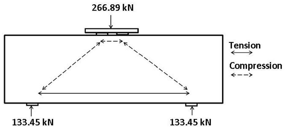
Assumed truss model for disturbed region.
Materials
The locally available Ordinary Portland Cement (OPC) conforming to the ASTM Standard C150-07 was used in the research program (ASTM, 2007). The fine aggregate was natural river sand having a fineness modulus of 2.3. The coarse aggregate used was crushed limestone with a maximum size of 19 mm and a bulk specific gravity of 2.72. Superplasticizer (SIKAMENT 163) equal to 2% of the weight of cement was used. The proportions of the concrete mixtures were 1:1:2 by mass of cement, sand, and gravel respectively. The mix was designed to produce a concrete with 28 days cylindrical strength of about 41.37 MPa. The water-cement ratio (w/c) was kept at 0.30 and the deformed steel (Grade 420) was used in the test beams.
Preparation and casting of test specimens
Test beams were cast using six batches of concrete (three beams per batch) having nomenclature as shown in Table 1. The forms were removed after 2 days of casting, and the beams were wrapped in wet hessian cloth. Curing was continued by keeping the hessian cloth wet until the time of testing, that is, at the age of 28 days. The concrete beams and cylinders were cast at the same time without any significant gap using the same concrete batch. All specimens were kept for curing in the same environment as maintained for beam specimens.
Experimental test results for unstrengthened RC deep beams.

Tests
Eighteen cylindrical specimens (three cylinders for each batch) were tested at the age of 28 days. Error bars were drawn in graphs to show the variability of results. The compressive strength of concrete cylinders was determined as per BS EN 12390-3 (EN, 2002). The workability of the concrete was measured in terms of slump, which was determined for each batch following the procedure laid down in ASTM C 143-78 (ASTM, 2003). Three specimens were tested from each mix. The workability of concrete was measured in terms of the slump as per ASTM C 143 and a slump of 90 ± 10 mm was noted. Average compressive strength of 44 MPa was achieved. This value was taken as the average of the compressive strength of 18 samples at the age of 28 days including three cylinders for each batch.
Test specimen details
The research program consisted of 18 RC deep beams with rectangular section. These beams were further divided into three groups. The specimens without CFRP were designated as GZ-BXF, where X, Z, and F show the number of beam specimen, group number, and unconfined specimen respectively. The CFRP wrapped specimens were designated as GZ-BXC, where X, Z, and C shows the number of beam specimen, group number, and CFRP strengthened specimen respectively. Depths were kept equal to 305, 457, and 610 mm for G1, G2, and G3 respectively. Shear span to depth ratio was 1.65, 0.90, and 0.62 for G1, G2, and G3 respectively. Each group consisted of six similar beams, of which three beams were control beams. The other three beams were strengthened with 229 mm width strips of CFRP, applied perpendicular to the expected crack pattern observed from results of control beams.
Reinforcement details
The deep beams were over-reinforced in flexure to achieve the objectives of the research. Reinforcement details are shown in Figure 2 and reported in Table 1. Figures 3 to 5 shows the reinforcement details of each group and Figures 6 to 8 shows their cross-sections.

Details of the beam specimen.

Reinforcement details for the beams of Group G1.

Reinforcement details for the beams of Group G2.

Reinforcement details for the beams of Group G3.
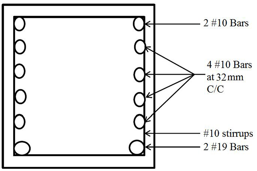
Section AA.

Section BB.
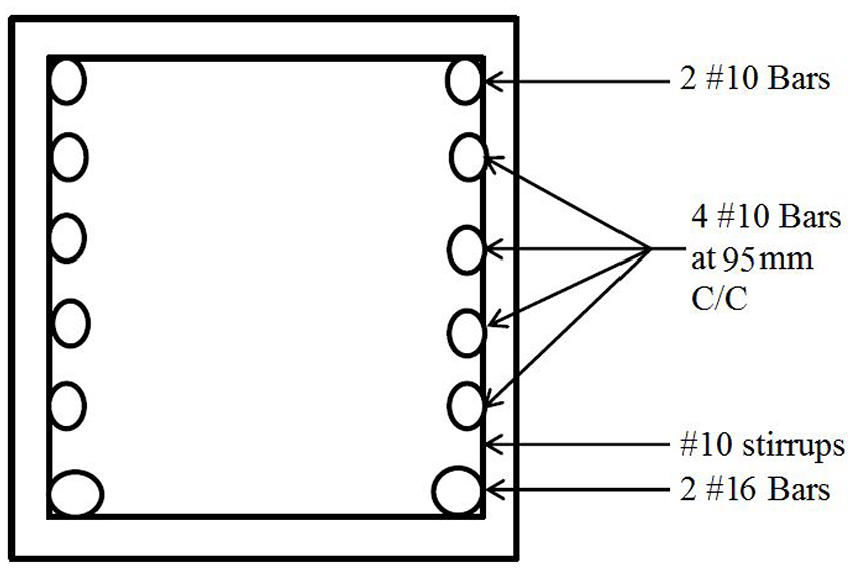
Section CC.
Test setup and instrumentation
A typical four-point bending experiment was designed for the tests as shown in Figures 9 and 10. The load was applied on two points at the mid-span of beams by a 2000 kN proving ring as shown in Figure 3. The shear span was 1.245 mm and the span to depth ratio was varied for each group.
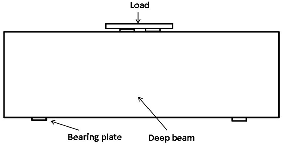
Loading arrangement.
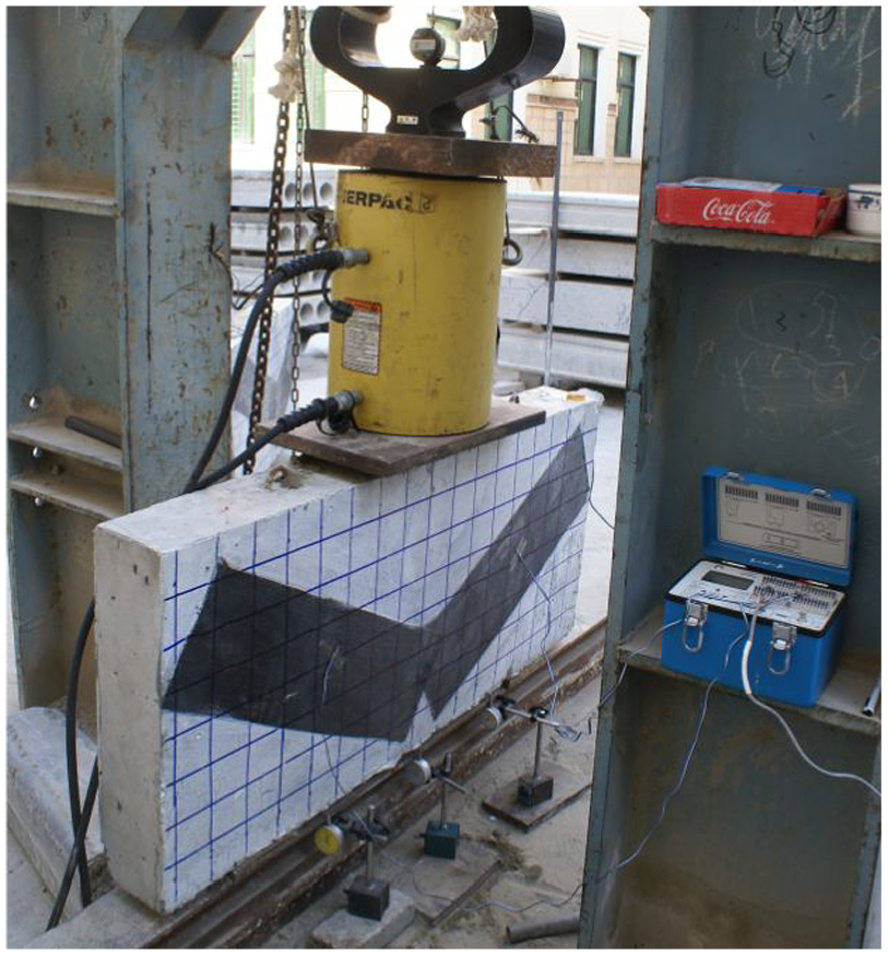
Loading setup.
The applied load was consistently increased at a low rate and recorded by load cell having an accuracy of 0.05 kN. Initial crack and crack patterns were noted at each increment in load. Cracks were marked on each face of the beams throughout testing.
The deflection for every interval of the load was measured with micro-measurements linear variable displacement transducers (LVDTs) having an accuracy of 0.01 mm. Linear pattern micro measurement strain gauges along with P3 strain indicators were used to record strains on the surface of beams.
Strengthening technique and properties of CFRP
For strengthening deep beams, CFRP strips were applied perpendicular to the probable crack pattern as observed from the results of control beams. CFRP strip orientation was adopted due to its effectiveness (Szabó and Balázs, 2007). A commercially available single layer of CFRP wrap was applied after the application of adhesive. The data related to the physical and mechanical properties of unidirectional CFRP laminate were provided by the manufacturer. The elastic modulus, tensile strength, and ultimate elongation of CFRP laminate were 234,500 MPa, 4900 MPa, and 1.7% respectively. Moreover, the coupon test results showed the ultimate strength of 5235 MPa. The elastic modulus and elongation were recorded as 253,430 MPa and 1.75% respectively. The surface of the specimens was cleaned to get rid of sand and other impurities.
Results and discussions
Crack propagation
The observed crack pattern for the control beam of G3 is shown in Figure 11. Initially, flexural cracks appeared in the middle of the deep beam under the influence of a small load. These cracks did not propagate in an upward direction due to over-reinforcement in tension. Deflection increased with increasing load and shear compression cracks were developed at the corner of supports. These cracks propagated upwards due to the increment of load and shear failure was observed. Similar cracking and failure behavior was observed in RC beams of all the groups.
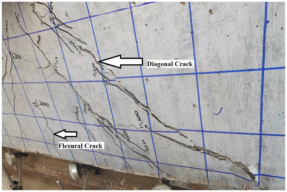
Typical observed crack patterns for control beams.
The behavior of CFRP strengthened beams of G3 is shown in Figure 12. The shear crack appeared that propagated with the increment of load. This crack propagation continued till the interception of the CFRP strip. Further increase in load was carried by the CFRP strips until the ultimate capacity of CFRP which caused the de-bonding of the CFRP sheet. Shear crack crossed the CFRP sheet and propagated towards the top surface. This unique behavior of shear crack propagation was observed in beams of all the groups.
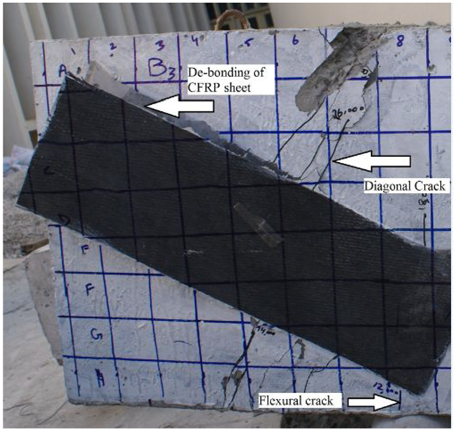
Typical observed crack patterns for CFRP strengthened beams.
Ultimate failure load
Ultimate failure load at different stages are discussed below
Control beam
The designed shear values from STM for the groups G1, G2, and G3 were 167.5, 251.1, and 334.9 kN respectively. Experimentally obtained shear strength values at different stages are reported in Table 1 and presented in Figure 13. The observation at different stages concerning average values for all the three control beams of each group is discussed. For beams of group G1, flexural cracks first appeared around 47% of failure load. Further, the shear compression cracks developed around 62% of the failure load. For beams of group G2, the flexural cracks were observed at about 38% of failure load and shear compression cracks occurred at about 49% of failure load. Finally, the flexural cracks for the beams of group G3 were noticed at approximately 34% of the failure load. The shear compression cracks originated at about 44% of the failure load. Further, the failure load for the beams of groups G1, G2, and G3 were observed as 669.41473, 1061.1237, and 1381.848 kN, respectively.
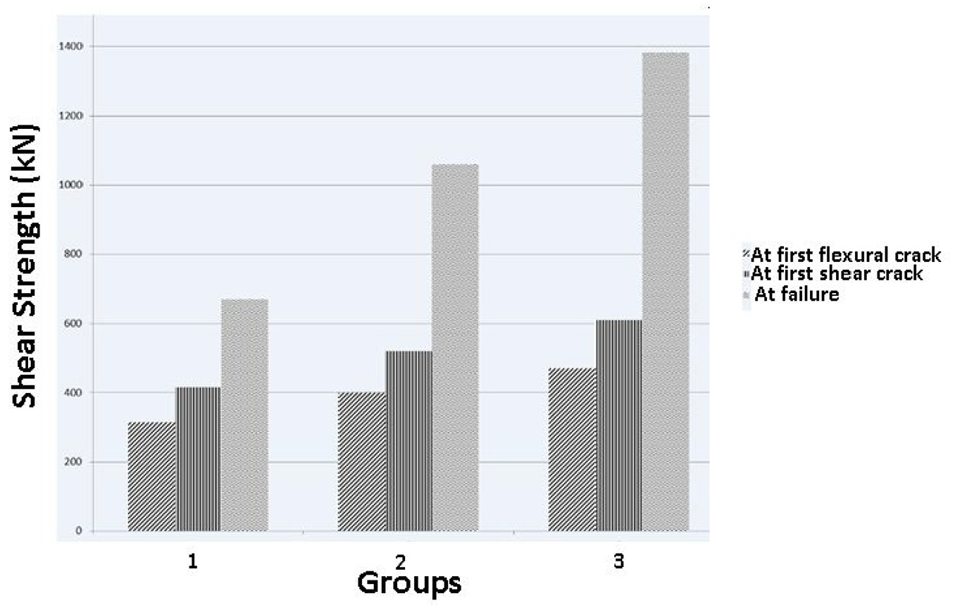
Comparison of shear for control beams (G1-3).
CFRP strengthened beam
Experimentally recorded shear strength values at different stages are shown in Table 2 and presented in Figure 14. The observations were made at different stages during the testing of deep beams strengthened with CFRP strips. For beams of group G1, the appearance of flexural cracks was observed at approximately 43% of failure load. Moreover, the shear compression cracks were seen at about 56% of the failure load. For beams of group G2, flexural cracks appeared at approximately 35% of failure load followed by shear compression cracks developed at about 50% of failure load. Flexural cracks for the beams of group G3 originated at approximately 31% of failure load and shear compression cracks were observed at about 46% of failure load. The values of failure loads for beams of G1, G2, and G3 were observed to be equal to 781.8421, 1221.526, and 1494.0325 kN, respectively.
Experimental test results for CFRP strengthened RC deep beams.

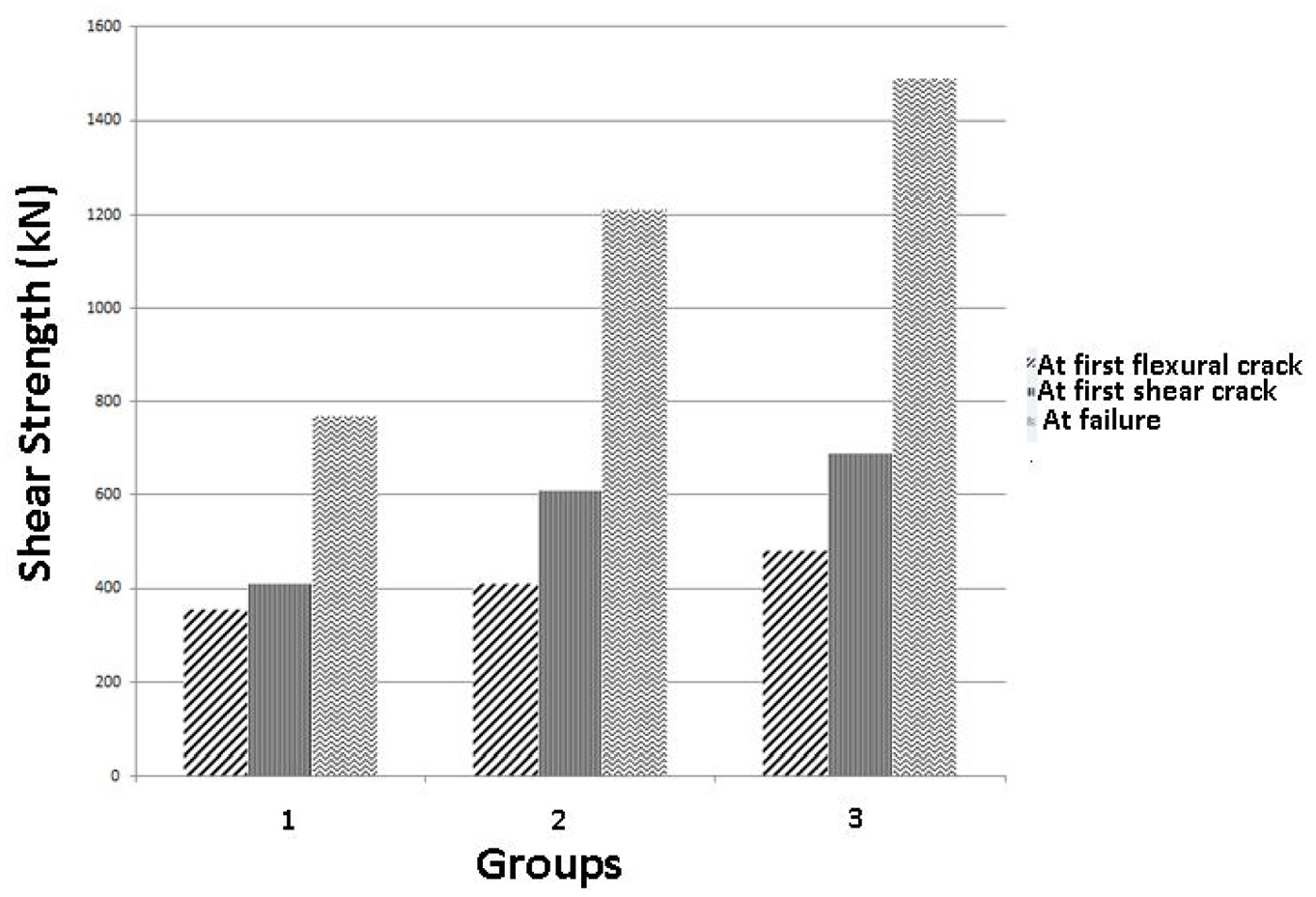
Comparison of shear for CFRP strengthened beams (G1-3).
Deflections
Average mid-span deflections of all the beams (control and strengthened) for each group are shown in Figure 15. It was noticed that by increasing the depth of deep beams, the mid-span deflection decreased. CFRP strengthened Beams showed an increase in the mid-span deflections as compared with those of control beams.
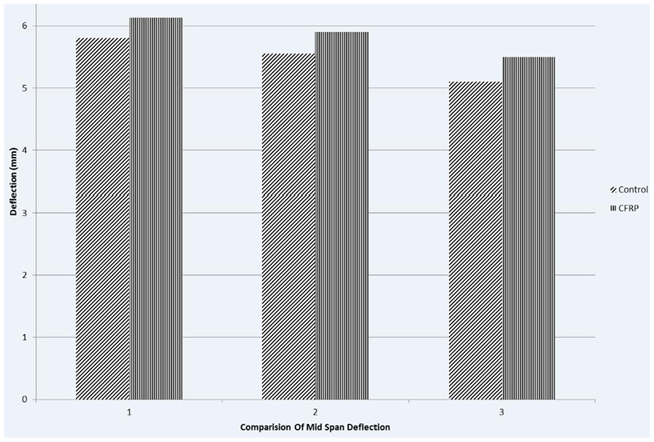
Comparison of mid-span deflections (G1-3).
Mid-span deflection decreased by 7% and 15% by increasing 50% and 100% depth respectively for control beams. The mid-span deflection in CFRP strengthened beams increased by 6% as compared to control beams for all groups.
Energy dissipation
Loads were applied to the specimens till failure and the corresponding deflections were measured. The specimens were then unloaded and deflections were again noted at each load decrement. Therefore, two curves were associated with each specimen. Total energy absorption for the specimen was measured from the area under the load-deflection curve. Similarly, the energy released is given by the area under the load-deflection curve observed during the unloading. Energy dissipation relates to the difference in areas under the loading and the unloading curves or the area bounded by the load-deflection curve. Trend line equations were obtained for each curve. Then using MATLAB software, areas under the curves were calculated from these equations which were indicative of energy. Total energy absorbed, dissipated, and released for all the groups are presented in Figures 16 and 17. Each bar represents the energy value of one group which is an average of three identical samples.
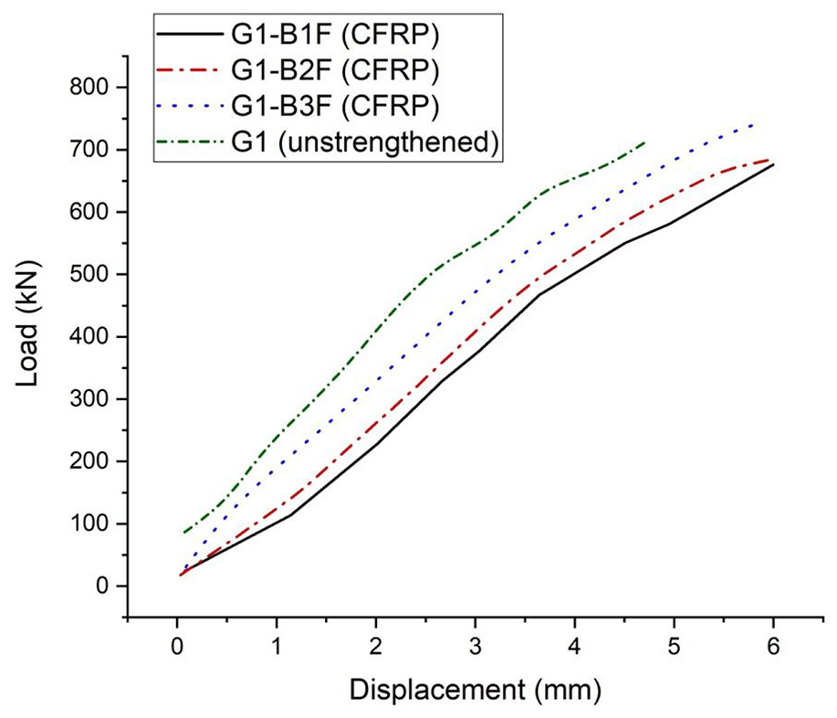
Load displacement curves (G-1).
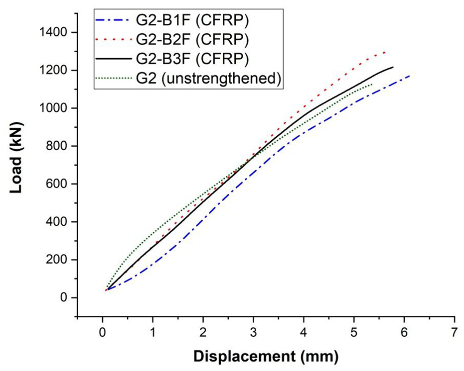
Load displacement curves (G-2).
The absorbed energy for beams reinforced with CFRP strip was observed. It was concluded that the energy absorbed for the beams of groups G1, G2, and G3 were 43%, 6%, and 15% more than the energy absorbed in control beams. The energy released in control beams was 45% more than in CFRP strengthened beams. The energy dissipated in beams of G1 was 77% more than the energy dissipated in control beams. The energy dissipated in beams of G2 was 32% more than that observed in control beams, the energy dissipated in beams of G3 was calculated as 64% more than the energy dissipated in control. Figure 18 shows the load displacement curve for Group-3. Comparison of energy absorption and dissipation for control and CFRP strengthened beams is shown in Figures 19 and 20 respectively.
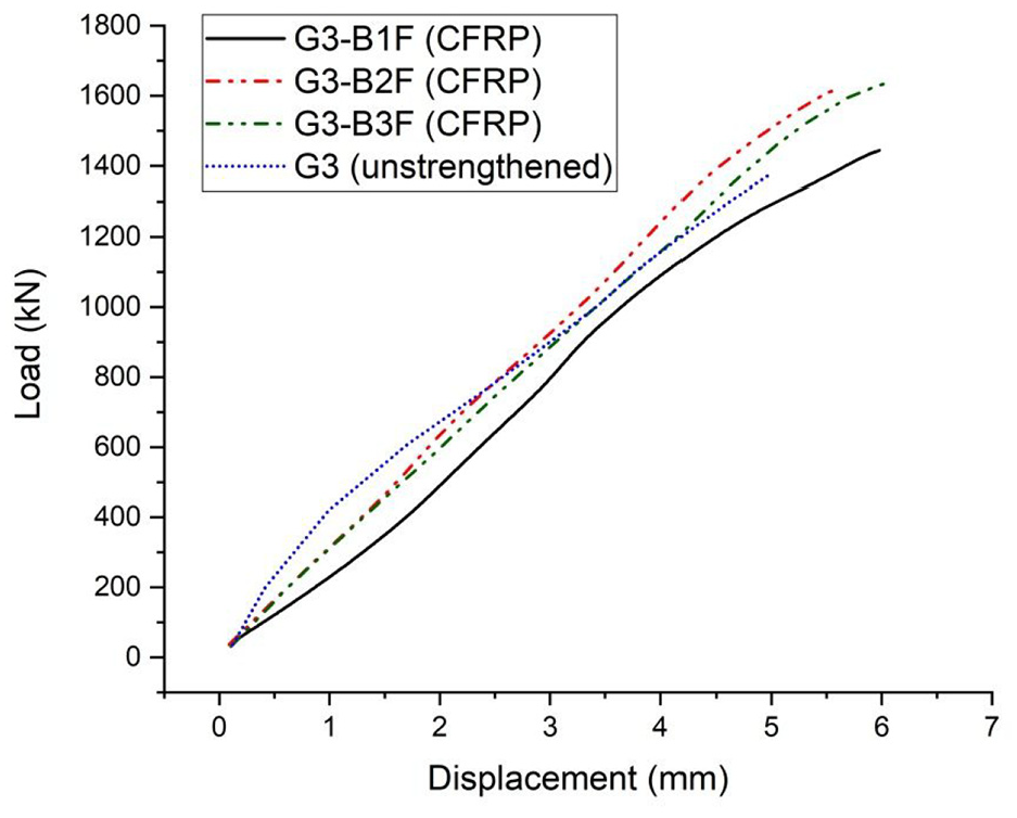
Load displacement curves (G-3).
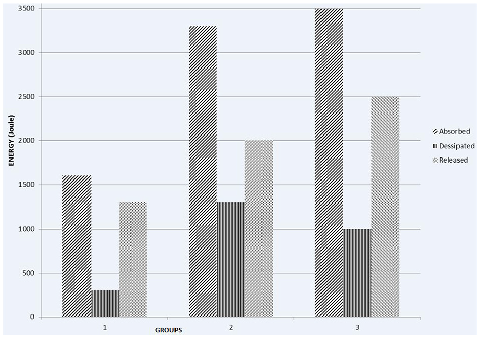
Comparison of energy absorbed, dissipated and released for control beams (G1-3).
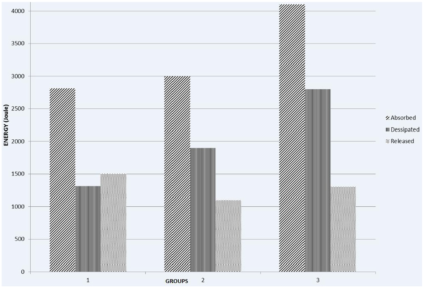
Comparison of energy absorbed, dissipated and released for CFRP strengthened beams (G1-3).
Strength equation
The existing design codes were assessed for their application of FRP strengthened RC deep beams. The contribution of FRP to shear resistance can be determined using existing models and design guidelines. Two well-known existing design guidelines (American concrete Institute (ACI 440 02) and Canadian Standard (CS S6.06) were used to predict the shear strength of CFRP strengthened RC deep beams (440 AC, 2017; Association, 2006; Bhunga and Arora, 2012). The experimental test results were compared with the predicted values of ACI and CS design code. The shear strength contribution of FRP strengthened RC beams is given by the following equation according to ACI 440.02 design guideline (equation (1)).

Where
The Canadian Standards (CS S06.06) design code for the FRP contribution to shear strength is shown in equation (2).

Where
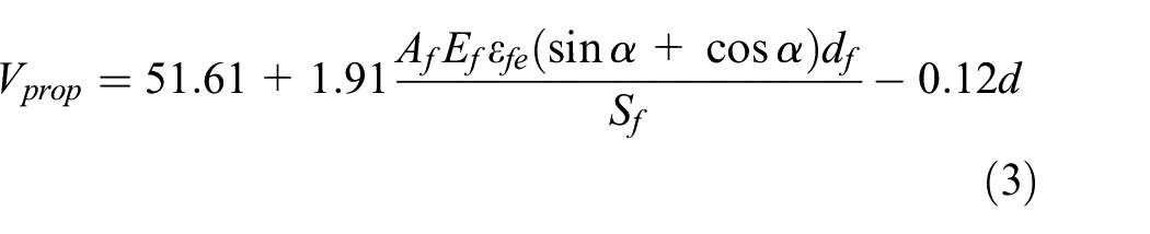
The results from the analytical design guidelines were compared with the experimental test results. A comparison of the experimental results with the design code ACI 440.2R.02 is given in Table 3. From these experimental results, a strength equation is developed. Following is the proposed equation based on the regression analysis (equation (3)
Experimental versus theoretical prediction of shear strength for CFRP strengthened RC deep beams.

Vprop and Vtheo shows experimental and theoretical (proposed) shear strength values.
Where Vprop is the shear strength contribution of FRP jackets to CFRP strengthened RC deep beams,
Conclusions
The following conclusions were observed from the research as shown:
The CFRP sheets enhanced the shear strength of RC deep beams up to 17% as compared to the un-strengthened (control) ones. The depth of deep beams directly affected the shear strength. Increasing the depth of deep beams led to its superior performance with CFRP sheets.
The shear strength behavior of RC deep beams is significantly improved by increasing the depth of the control beams. The shear strength enhancement of 58% and 106% was observed in control RC deep beams with 58% and 106% increment in its depth.
Energy absorption increased in the case of CFRP strengthened beams confirming their relatively less brittle behavior as compared to that exhibited by control beams.
American Concrete Institute (ACI 440.02) and Canadian Standard (CS S6.06) overestimated the experimental test results for shear strength of RC deep beams strengthened with CFRP sheets.
The modified ACI shear strength equation agreed well with the experimental test results. However, the modified equation is valid for CFRP strengthened RC beams.
Footnotes
Appendix
Declaration of conflicting interests
The author(s) declared no potential conflicts of interest with respect to the research, authorship, and/or publication of this article.
Funding
The author(s) received no financial support for the research, authorship, and/or publication of this article.
