
Abstract
Six lightweight aggregate concrete (LWC) beams reinforced with carbon fiber–reinforced polymer (CFRP) bars were tested under a four-point bending load with different steel fiber contents, reinforcement ratios, and clear span lengths to investigate their flexural behavior and serviceability performance. The test results showed that using steel fiber–reinforced lightweight aggregate concrete (SFLWC) and increasing the reinforcement ratio enhanced the serviceability performance of the beams. The incorporation of 0.6% by volume of steel fibers reduced the midspan deflection by 22.70%–36.87% at the same load level in service stage. At service load, all the CFRP-reinforced beams exhibited conservative deflections when compared to the deflection limits recommended by ACI 440.1 R and GB 50608, and satisfied the crack width limit of 0.7 mm. Comparing the measured maximum crack widths with the corresponding predictions revealed that the bond-dependent coefficient value of 1.4 specified in ACI 440.1 R was reasonable yet conservative. Moreover, an energy-based method was adopted to quantify the influence of the fibers on the beam stiffness. On this basis, a rational deflection model for SFLWC beams reinforced with CFRP bars was suggested.
Keywords
Introduction
Deterioration of concrete structures due to corrosion of steel reinforcement incurs exorbitant maintenance costs. With regard to the inherent corrosion-resistant performance, fiber-reinforced polymer (FRP) bars are considered as a viable substitute for concrete reinforcement (Hassan and Deifalla, 2016; Wang et al., 2019). Aramid fiber–reinforced polymer (AFRP) and glass fiber–reinforced polymer (GFRP) bars are common options applied in construction field due to their price advantage. However, the low creep rupture strength and durability problems in alkaline prevent them from being widely used. Carbon fiber–reinforced polymer (CFRP) bars with advantages of high tensile strength, high creep rupture strength, and good durability in various environments have received considerable attention (Malvar et al., 2003). Many research efforts have been devoted to the behavior of composite structures with CFRP bars (Ashour and Family, 2006; Li et al., 2019; Rafi et al., 2008).
Lightweight aggregate concrete (LWC) has been increasingly applied in engineering construction because of their light weight, good heat insulation, and high sustainability (Suraneni et al., 2016; Wu et al., 2019a; Zhou and Brooks, 2019). In the light of the advantages of LWC and CFRP, their combined use in bridge architectures could significantly lower the internal force, improve the durability, and reduce the life cycle costs. The design of FRP-reinforced concrete (FRP–RC) beams is usually governed by the requirements in the serviceability limit state owing to the low elastic modulus of the FRP bars (Elgabbas et al., 2017; El-Nemr et al., 2013). Nevertheless, the drawbacks of LWC, including low crack resistance and poor bond behavior, would bring adverse impacts on both deflection and cracking behavior of the beam members.
Adding fibers to concrete has been proven to be effective in enhancing the deflection and crack width of FRP–RC beams. Gribniak et al. (2013) carried out flexural tests on five simply supported GFRP-reinforced beams and found that the post-cracking stiffness of the beams increased noticeably when steel fibers were used. Zhu et al. (2018) conducted an experimental study on flexural behavior of partially fiber-reinforced high-strength concrete beams reinforced with FRP bars. It was reported that the specimens with steel fibers in their tension zone experienced great benefit to the deflection and cracking behavior. Abed and Alhafiz (2019) investigated the effect of basalt microfibers on the flexural behavior of concrete beams reinforced with basalt fiber–reinforced polymer (BFRP) bars. They concluded that introducing basalt fibers to the concrete improved curvature ductility of the beams and helped restrain the opening of cracks.
Although extensive research work has been performed to characterize the cooperative working performance between CFRP reinforcements and concrete (Dong et al., 2019; Thamrin and Kaku, 2007; Thiagarajan, 2003), very few papers are available on the behavior of CFRP-reinforced fibrous LWC beams. Accordingly, in this study, six CFRP-reinforced beams fabricated using LWC and steel fiber–reinforced lightweight aggregate concrete (SFLWC) were tested under four-point bending to investigate their serviceability performance. The experimental midspan deflections and crack widths at service load were used to assess the accuracy of code provisions and previous models.
Experimental program
Material
Concrete
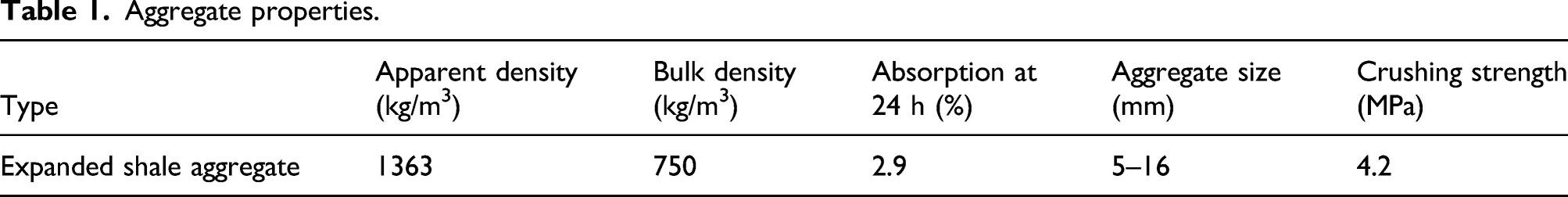
Aggregate properties.

Appearance of steel fibers.
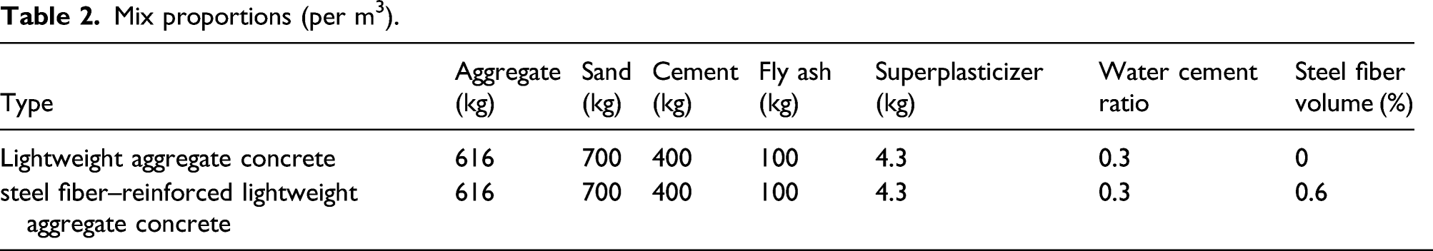
Mix proportions (per m3).

Uniaxial compressive stress–strain curves of LWC and SFLWC (Wu et al., 2021). Note: LWC: lightweight aggregate concrete; SFLWC: steel fiber–reinforced lightweight aggregate concrete.
FRP bars
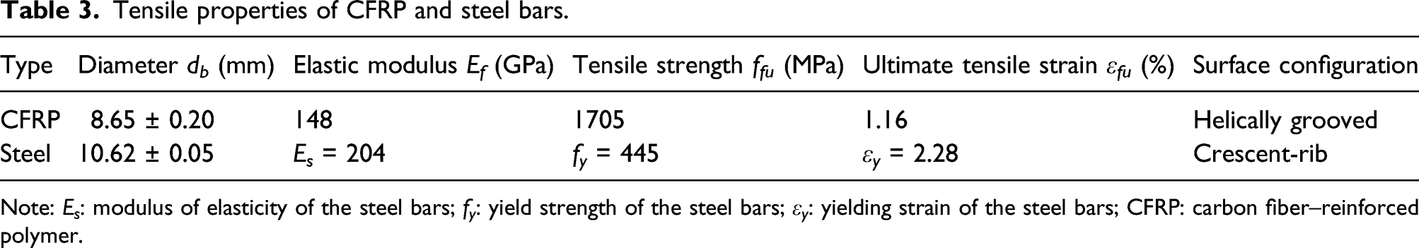
The CFRP bars used in this study were manufactured using carbon fibers impregnated in vinyl ester resin. The CFRP bars with a diameter of 8.65 mm had a helically wound fiber on their outside to produce grooved surface (Figure 3). Grade-400, 10.62 mm steel bars were used as transverse and top reinforcements in the specimens. The diameters and mechanical properties of the CFRP bars were determined by tests according to ACI 440.3R (ACI 2012). The CFRP bars behaved a linear elastic behavior in tension until failure and exhibited no yielding. The mechanical properties of the CFRP and steel bars are shown in Table 3. Appearance of carbon fiber–reinforced polymer bars. Tensile properties of CFRP and steel bars. Note: E
s
: modulus of elasticity of the steel bars; f
y
: yield strength of the steel bars; ε
y
: yielding strain of the steel bars; CFRP: carbon fiber–reinforced polymer.
Specimens
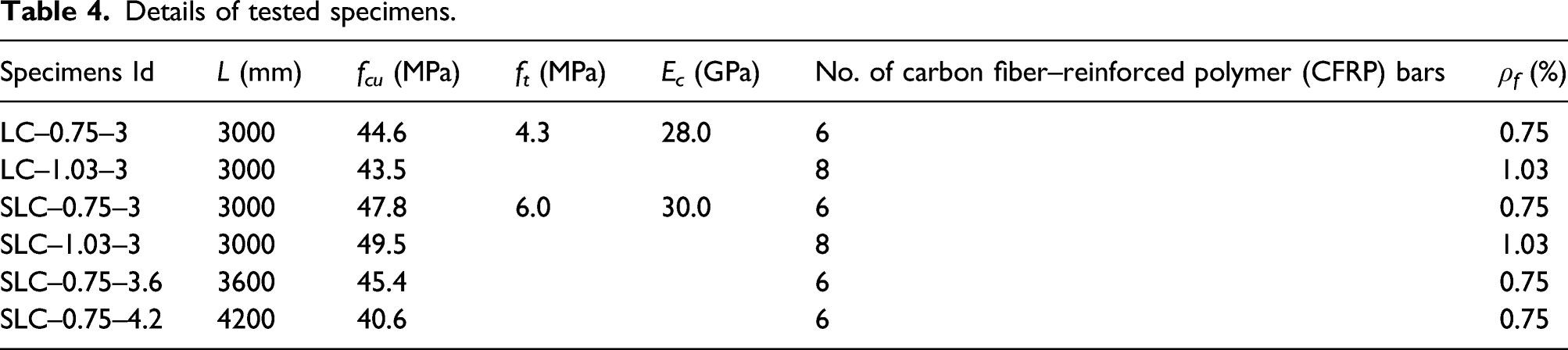
Six simply supported beams with a cross-sectional dimension of 200 × 300 mm were fabricated and tested, as displayed in Figure 4. Two different reinforcement ratios (ρ
f
) (0.75 and 1.03%) and three different lengths of clear span (L) (3, 3.6, and 4.2 m) were used. The total length of each specimen included two parts of 300 mm beyond the supports to prevent slippage of the CFRP reinforcements. In addition, the beams were provided with sufficient steel stirrups (10 mm at 100 mm) in the shear spans to avoid shear failure. To minimize the confining effect on the flexural behavior, the space of stirrups in the constant moment zone was increased to 200 mm. Table 4 provides the dimensions and reinforcement details of the tested beams. The specimens were labeled as follows: The beam types were identified as A–B–C. The symbols “LC” and “SLC” denote the type of the concrete, the second nomenclature identifies the reinforcement ratio, and the final nomenclature denotes the length of the clear span. For example, LC–1.03–3 indicates a lightweight aggregate concrete beam with a ρ
f
of 1.03% and an L of 3 m. Specimen details (dimensions in mm). Details of tested specimens.
Test setup and procedure
The specimens were tested under four-point bending with 4/15 L distances between loads. The schematic representation and actual laboratory test setup are shown in Figure 5. A 500 kN hydraulic jack applied the load to the specimens gradually through a rigid steel spreader beam. The specimens were supported on a hinged support and a roller support both with a size of 150 × 250 × 130 mm3. The beams were tested in force-control at a speed of 0.5 kN/min until cracking, and subsequently loaded in deformation-control at a rate of 1 mm/min until failure. A load cell was attached to the underside of the hydraulic actuator to monitor the applied force. To monitor beam deformation comprehensively, linear variable displacement transducers (LVDTs) were installed at midspan, loading point, and middle of the shear span, respectively. Furthermore, midspan strains of the CFRP bars were captured using strain gauges with a length of 5 mm. At the end of each load increment (4 min), crack widths were measured using hand-held optical microscopes and all the data were fed into a data acquisition system. Test setup: (a) Schematic representation; (b) Actual laboratory test setup.
Test results
Cracking moment
Experimental results.
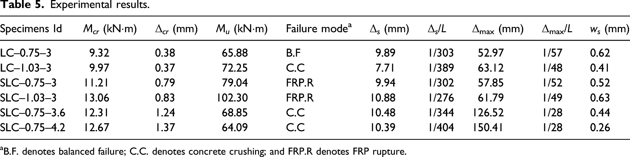
aB.F. denotes balanced failure; C.C. denotes concrete crushing; and FRP.R denotes FRP rupture.
Comparing beams LC–0.75–3 and LC–1.03–3, which had the same concrete type and L, revealed close midspan deflections at M cr (Δ cr ). Similar results were observed for SFLWC beams SLC–0.75–3 and SLC–1.03–3. Beams SLC–0.75–3, SLC–0.75–3.6, and SLC–0.75–4.2 with the same concrete type and ρ f gave an indication of the effect of L. As expected, the Δ cr tended to increase with increasing L.
Failure mode
The tested beams exhibited three different failure modes. The first was concrete crushing observed in specimens LC–1.03–3, SLC–0.75–3.6, and SLC–0.75–4.2. The second was FRP rupture observed in specimens SLC–0.75–3 and SLC–1.03–3. The third was defined as balanced failure where compressive concrete failure followed immediately by rupture of the FRP bars and it was observed in beam LC–0.75–3.
Typical failure shapes are presented in Figure 6. As can be seen, for beams failed by concrete crushing, cracks through the lightweight aggregates (LWAs) were observed at the broken surface, which could be attributed to the low compressive strength of the LWAs. The LWC beam LC–1.03–3 (Figure 6(a)) experienced explosive spalling of concrete in the compression zone, while no serious disintegration occurred in the SFLWC beams SLC–0.75–3.6 and SLC–0.75–4.2 (Figures 4(b) and (c)), owing to the contribution from the steel fibers. In addition, the range of the crushed concrete was larger in beam SLC–0.75–3.6 than that in beam SLC–0.75–4.2, although both of them experienced concrete crushing. Failure modes: (a) LC–1.03–3; (b) SLC–0.75–4.2; (c) SLC–0.75–3.6; (d) LC–0.75–3; and (e) SLC–0.75–3 (Wu et al., 2021).
As shown in Figure 6(d), for beam LC–0.75–3 that failed by balanced failure, concrete crushing occurred with a small scale in the compression zone. In addition, both FRP rupture and balanced failure modes were characterized by a large vertical crack in the constant moment region (Figures 6(d) and (e)). The CFRP bars were fractured and the fiber bundles which wound around the bars were snapped. Horizontal cracks at the level of the CFRP reinforcement were typical behaviors seen in these failure modes. The formation of these cracks could be a result of the slip between the CFRP bars and the surrounding concrete. Moreover, the deformations of the specimens partly recovered after unloading, even in beams failed by FRP rupture, indicating that the CFRP bars did not rupture simultaneously. It could be deduced that the strength of the CFRP bars was of high discreteness.
Moment–deflection relationship
The moment–midspan deflection responses of the specimens are depicted in Figure 7. All the tested beams yielded typical bilinear relationships before the peak load, namely, a steep linear stage that described the uncracked condition and a basically linear stage that represented the reduced post-cracking stiffness. This result complimented the findings of Issa et al. (2011) for FRP-reinforced normal weight concrete (NWC) beams with and without fibers. Additionally, for specimens experienced concrete crushing (LC–1.03–3, SLC–0.75–3.6, and SLC–0.75–4.2), a nonlinear stage that corresponded to the crushing process was observed after the peak load. In this stage, the load progressively decreased with increasing deformation. The inelastic deformations near failure lent a degree of ductility for this failure mode, which was in agreement with the results reported for GFRP-reinforced NWC beams with and without fibers (Yang et al., 2012). Moment–deflection relationships: (a) Specimens with an L of 3 m; (b) steel fiber–reinforced lightweight aggregate concrete beams with a ρf of 0.75%.
Figure 7(a) indicates that increasing the ρ f enhanced the post-cracking stiffness of the beams, regardless of the concrete type. Given the same ρ f , using SFLWC resulted in lower deflections at the same load level. This could be attributed to the fact that the steel fibers inhibited the formation and development of the cracks. Gribniak et al. (2013) also reported the benefit offered by fibers achieved in stiffness for FRP-reinforced NWC beams. From component size point of view, a greater increase in the deflection was found in the portion from three to 3.6 m compared to that within the 3.6–4.2 m.
Midspan deflection
At service load
The design of FRP–RC beams is usually governed by the serviceability limit state requirements due to the low elastic modulus (E f ) of the FRP bars. Based on Bischoff et al. (2009) recommendation, 30% of the ultimate moment (M u ) was considered a service load (M s ) for FRP–RC beams. The midspan deflections at M s (Δ s ) of the specimens are given in Table 5 and are represented by filled points on the curves in Figure 7.
Comparing specimens LC–0.75–3 and LC–1.03–3 revealed lower Δ s in specimens with higher ρ f . However, in regard to the SFLWC beams, the Δ s of specimen SLC–1.03–3 was higher than that of specimen SLC–0.75–3. The conflicting results could be attributed to the fact that increasing the ρ f had both positive and negative influences on the Δ s , more specifically, improving the M s as well as lowering the deflection simultaneously. For similar reasons, no clear effect of the incorporation of the steel fibers on the Δ s was observed. To assess the benefit offered by the steel fibers, deflections of LWC and SFLWC beams with the same ρ f were compared. At 19.76 kNm (service load of beam LC–0.75–3), the midspan deflection of beam SLC–0.75–3 was 36.87% lower than that of its plain counterpart LC–0.75–3. Similarly, at 23.71 kNm (service load of beam LC–1.03–3), specimen SLC–1.03–3 yielded 22.70% lower deflection when compared to beam LC–1.03–3.
Experimental results also showed that increasing the L did not significantly increase the Δ s . This could be a result of the lower M u of specimens SLC–0.75–3.6 and SLC–0.75–4.2 compared to that of beam SLC–0.75–3.
GB 50608 (GB, 2010) provided a deflection limit of L/200 for FRP–RC beams, namely, 18 mm for SLC–0.75–3.6, 21 mm for SLC–0.75–4.2, and 15 mm for the rest of the specimens, as illustrated in Figure 7. ACI 440.1 R (ACI, 2015) recommended an allowable deflection of L/240. On the basis of these specifications, the Δ s of the CFRP-reinforced beams were relatively conservative. Moreover, CSA S806 (CSA, 2012) specified a stricter limit of L/360 and only two specimens (LC–1.03–3 and SLC–0.75–4.2) fulfilled this requirement.
At failure
After the peak load, the beams that were damaged by concrete crushing continued to sustain loads with increasing deformation. Thus, in order to evaluate the deformability, the maximum deflection (Δmax) of these specimens was defined as the deflection at the residual load corresponding to 85% of the M u , as shown in Figure 7. Table 5 presents the Δmax of all the CFRP-reinforced beams. The ratios of Δmax/L of the specimens with an L of 3 m varied from 1/57 to 1/48. Comparing beams LC–0.75–3 and LC–1.03–3 revealed higher Δmax/L in beam with greater ρ f . The same trend was seen in the case of the SFLWC beams. Moreover, specimens SLC–0.75–3.6 and SLC–0.75–4.2 yielded fairly higher Δmax/L in comparison to their short-span counterpart SLC–0.75–3, which could be explained by their more gradual failure mode.
Strain in reinforcement
Figure 8 shows the midspan tensile strains in the FRP bars (ε
f
) versus the applied moment. It should be noted that the ε
f
at ultimate stage were not monitored due to the invalidating of the strain gauges. The shapes of the moment–ε
f
responses were analogous with respect to the first two stages of their moment–midspan deflection relationships. This was consistent with the findings of Gribniak et al. (2013) and Kassem et al. (2011) for FRP-reinforced NWC beams with and without steel fibers, respectively. Furthermore, the effects of steel fibers and ρ
f
on the moment–ε
f
responses were in agreement with those on the moment–midspan deflection relationships. Moment–midspan fiber-reinforced polymer strain relationships.
Additionally, as presented in Figure 8, increasing the L while maintaining the ρ f increased the ε f at the same load level. Since the curves presented in the figure reflected the ε f at the location of the gauges, based on the assumption that L had a marginal effect on the tensile strains of the FRP bars at the location of cracks (GB, 2010), it could be deduced that increasing the L delivered a more uniform deformation of the CFRP bars, and consequently a higher ε f .
Cracking behavior
Figure 9 illustrates the relationships between the applied moment and the maximum crack width (wmax) of the tested beams. To highlight the stage of interest, the maximum service loads of the specimens are also plotted in Figures 9(a) and (b). As shown in Figure 7(a), the wmax of beam SLC–0.75–3 was smaller than that of beam LC–0.75–3 during the entire loading period. In regard to beams with a ρ
f
of 1.03%, adding steel fibers decreased the wmax before the moment of 30.69 kNm (M
s
of beam SLC–1.03–3). However, at high load levels, the benefit offered by the steel fibers became invalid with respect to the size of the crack widths since the fibers at the crack surfaces pulled out successively with increasing load. Similar observations were reported for the cracking characteristics of GFRP-reinforced LWC beams with short steel fibers (Wu et al., 2019a). Moment–crack width relationships: (a) Specimens with an L of 3 m; (b) steel fiber–reinforced lightweight aggregate concrete beams with a ρf of 0.75% (Liu et al., 2020).
The maximum crack widths at M s (w s ) of the specimens are given in Table 5 and are represented by black symbols on the curves in Figure 9. As can be seen, specimens with larger L exhibited smaller w s . The benefit of increasing the L was especially true when comparing specimens SLC–6#8–3.6 and SLC–6#8–4.2, which attained comparable M s .
Since the FRP reinforcement is noncorrodible, flexural crack width limits specified in the FRP–RC design codes were more relaxed than those for steel-reinforced elements. GB 50608 (GB, 2010) allowed crack widths of 0.5 mm for both interior and exterior exposure. ACI 440.1 R (ACI, 2015) and CSA S806 (CSA, 2012) recommended same crack width limits, namely, 0.5 mm and 0.7 mm for exterior and interior exposure, respectively. It can be seen from Table 5 that half of the specimens yielded w s higher than 0.5 mm, while all the beams satisfied the crack width criteria of 0.7 mm.
Evaluation of design code predictions
Cracking moment
The M
cr
for FRP-reinforced beams were calculated from equation (1) for both ACI 440.1 R (ACI, 2015) and CSA S806 (CSA, 2012). The modulus of rupture of the concrete f
r
was expressed by equation (2) for the CSA code and equation (3) for the ACI code. Taking into account the negative effect of lightweight aggregates on the tensile strength of the concrete, the reduction factor λ=0.85 was employed as recommended by ACI 318 (ACI, 2019)


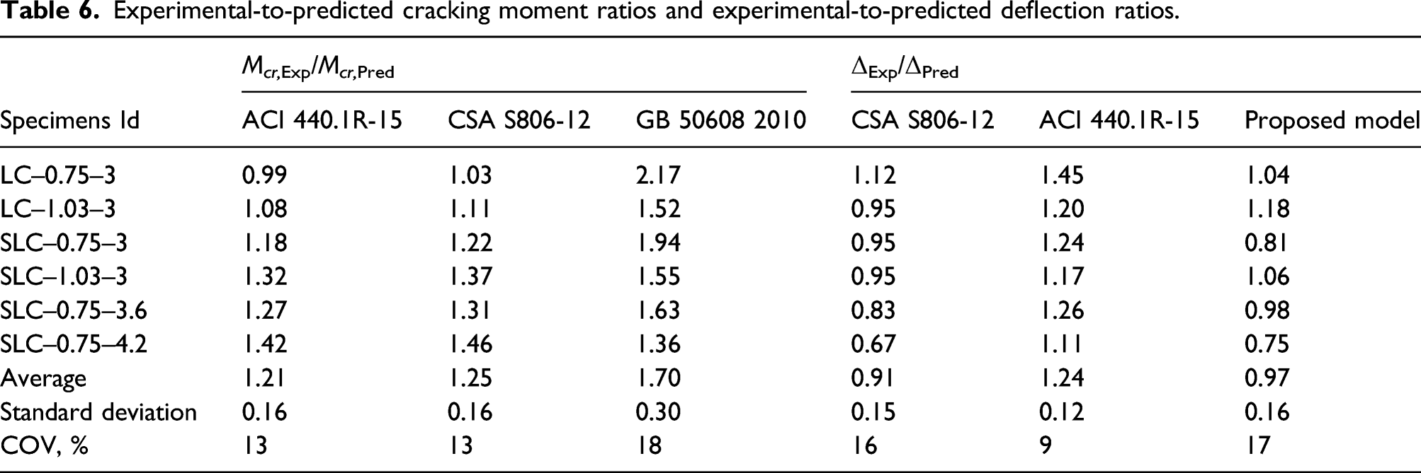
Experimental-to-predicted cracking moment ratios and experimental-to-predicted deflection ratios.
Deflection
Review of existing deflection models
In CSA S806 (CSA, 2012), moment–curvature method was employed to calculate the deflection of cracked FRP–RC members. For a beam under four-point bending, the midspan deflection was expressed as
ACI 440.1R (ACI, 2015) recommended an effective flexural stiffness method to estimate the deflection of FRP–RC beams, in which an effective moment of inertia (I
e
) expression incorporating tension stiffening (equation (5)) was provided

In GB 50608 (GB, 2010), the deflection prediction entailed the calculation of the short-term stiffness B
s


Comparison of experimental and predicted deflections
The experimental midspan deflections were used to assess the accuracy of the code provisions and previous models. Table 6 presents the experimental-to-predicted deflection ratios (ΔExp/ΔPred) for the specimens at M
s
and Figure 10 compares the measured and predicted deflections at various load levels. At M
s
, CSA S806 (CSA, 2012) gave reasonable yet conservative estimations, on average, with a ΔExp/ΔPred of 0.91 ± 0.15. ACI 440.1R (ACI, 2015) slightly underestimated the deflection predictions with average ΔExp/ΔPred of 1.24 ± 0.12. Furthermore, very unconservative theoretical deflections were obtained when calculated by GB 50608 (GB, 2010), with an average ΔExp/ΔPred of 1.70 ± 0.30. Comparison of moment–deflection curves obtained from experiments and predictions: (a) LC–0.75–3; (b) LC–1.03–3; (c) SLC–0.75–3; (d) SLC–1.03–3; (e) SLC–0.75–3.6; and (f) SLC–0.75–4.2.
In addition, the ΔExp/ΔPred based on GB 50608 (GB, 2010) tended to decrease with increasing L. In the case of CSA S806 (CSA, 2012) and ACI 440.1R (ACI, 2015), the change in the L had no significant influence on the accuracy of the predictions.
As displayed in Figure 10, when the load exceeded the M cr , ACI 440.1R (ACI, 2015) yielded transition stages that were very similar with the experimental responses since the I e in equation (13) continuously changed from I g with increasing load. While each of GB 50608 (GB, 2010) and CSA S806 (CSA, 2012) exhibited an obvious increase in the deflection at M cr , which led to an overestimation of the deflections at this load level. In the second stage, the moment–deflection relationships obtained using the deflection equations followed the same trend. However, the slopes of the experimental curves were lower than those predicted by the calculation models for all the tested beams. At service load levels, the estimated values were relatively close to the experimental results. However, at high load levels, the specimens yielded fairly larger deflections than the estimated values.
Crack width
Review of existing crack width models
The crack width formulas recommended by ACI 440.1R (ACI, 2006) and ISIS-M03 (ISIS, 2007), as presented in equations (9) and (10), respectively, were both modified by the theoretical formulas proposed by Gergely and Lutz (1968). With respect to the parameters that were used to describe the interaction between concrete and FRP bars, bar spacing s was used by ACI 440.1R (ACI, 2006) and the effective tension area of the concrete surrounding each bar A was adopted by ISIS-M03 (ISIS, 2007). Moreover, a more conservative bond-dependent coefficient (k
b
) was recommended by ACI 440.1R (ACI, 2006) than ISIS-M03 (ISIS, 2007)

Comparison of experimental and predicted crack widths
Experimental-to-predicted crack width ratios and predicted k b values.
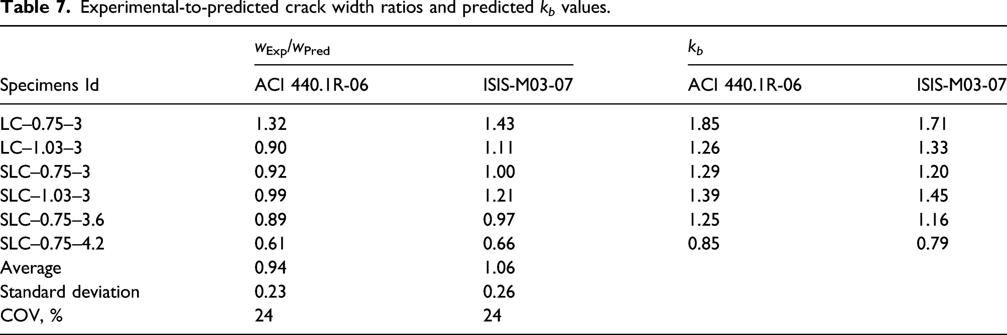
As shown in Table 7, the k b calculated using the measured crack widths ranged from 0.85 to 1.85 for ACI 440.1R (ACI, 2006), and from 0.79 to 1.71 for ISIS-M03 (ISIS, 2007). The results also indicated that the k b value of 1.4 specified in ACI 440.1R (ACI, 2006) was conservative for all the specimens except for beam LC–6#8–3. Furthermore, the 1.2 value assumed in ISIS-M03 (ISIS, 2007) was slightly unconservative for specimens with an L of 3 m while it was seen to be conservative for specimens with L of 3.6 and 4.2 m. According to both ACI 440.1 R (ACI 2006) and ISIS-M03 (ISIS 2007), the calculated k b was lower in beams with larger L. This finding corroborated with the experimental results discussed earlier that increasing the L tended to decrease the wmax at low load levels.
Figure 11 shows a comparison between the experimental moment–wmax responses and those predicted with ACI 440.1R (ACI, 2006) and ISIS-M03 (ISIS, 2007). The theoretical curves passed through the origin since the crack width was assumed to be in proportion to the applied moment, while the experimental curves started from M
cr
where the first cracking actually occurred. Hence, the code procedures showed conservative estimations at low load levels. Similar to the case of the deflection prediction discussed earlier, the increase rates of the measured crack widths were generally higher than those of the predicted values. Consequently, the wmax of the beams were underestimated by the codes at high load levels, except for beam SLC–0.75–3, for which the experimental moment–wmax relationship followed the same trend with the theoretical curve based on ACI 440.1R (ACI, 2006). Moreover, it could be observed that the degree of underestimation was higher for specimens with larger L. Comparison of moment–crack width curves obtained from experiments and predictions: (a) LC–0.75–3; (b) LC–1.03–3; (c) SLC–0.75–3; (d) SLC–1.03–3; (e) SLC–0.75–3.6; and (f) SLC–0.75–4.2.
Proposed deflection model
Deflection equation based on strain in FRP reinforcement
Wu et al. (2019a) specified the strain and stress conditions of FRP–RC elements at service load and established a deflection model based on the relationship between the average tensile strain of the FRP bar 
The 
For NWC beams, the M cr can be calculated by the equations recommended by ACI 440.1R (ACI, 2015).
Modification to average strain in FRP reinforcement
The experimental results showed that the concrete properties have significant impact on the beam stiffness. A modified version of 
For NWC beams, the elicited value of the λ = 1. For specimens cast using LWC, λ is equivalent to 0.85 owing to the low tensile strength of the concrete (ACI, 2019). Incorporating steel fibers improved the properties of the LWC, and thus helped restrain the stiffness degradation of the beams post-cracking. With this in mind, the ratio of energy density released and absorbed by concrete failure under uniaxial compression (A2/A1) is selected to reflect the contribution of the concrete from the definition of toughness (Figure 12), and thus β can be determined using Schematic of A1 and A2.

Furthermore, it has been proved that specimens with higher reinforcement amount gained less benefit from fibers (Abed and Alhafiz, 2019; Wu et al., 2021). In order to reflect this influence, factor ρ
fb
/ρ
f
is introduced and an alternative expression of β is given in equation (15)
Vertification
Table 6 and Figure 10 compare the estimations calculated from the proposed equations and the measured results. The theoretical deflections according to the proposed model were in agreement with the experimental results at low load levels. At M s , the proposed model gave the most accurate predictions among all the models studied herein, with an average ΔExp/ΔPred of 0.97 ± 0.16.
Moreover, the accuracy of the proposed model was further checked based on Wu et al. (2019a) experimental deflections for GFRP-reinforced LWC and SFLWC beams at M
s
. The ratios of ΔExp/ΔPred of the members collected and tested in this study are shown in Figure 13. Considering the overall results, the proposed model realistically estimated the deflections for the LWC beams with an average ΔExp/ΔPred of 1.02 ± 0.13, and yielded conservative predictions for the SFLWC ones with an average ΔExp/ΔPred of 0.84 ± 0.13. Comparison of service deflections obtained from experiments and predictions.
Conclusion
The main aim of this study was to investigate the flexural behavior and serviceability performance of CFRP-reinforced beams conducted using LWC and SFLWC. On the basis of the experimental results and prediction models presented herein, the following conclusions are drawn: Increasing the FRP reinforcement ratio was shown to be effective in enhancing the serviceability performance of the CFRP-reinforced LWC beams. The incorporation of 0.6% by volume of steel fibers reduced the midspan deflection by 22.70%–36.87% at the same load level in service stage. At service load, all the CFRP-reinforced beams exhibited conservative deflections when compared to the deflection limits recommended by ACI 440.1R (ACI, 2015) and GB 50608 (GB, 2010). However, only two specimens fulfilled the requirement specified in CSA S806 (CSA, 2012). In regard to crack width, half of the beams yielded maximum crack widths higher than 0.5 mm at service load, while all the specimens satisfied the criteria of 0.7 mm. Generally, the bond-dependent coefficient value of 1.4 specified in ACI 440.1R (ACI, 2006) was reasonable yet conservative for CFRP-reinforced LWC specimens with and without steel fibers. Moreover, the 1.2 value assumed in ISIS-M03 (ISIS, 2007) was slightly unconservative for specimens with a clear span length of 3 m but was conservative for those with clear span lengths of 3.6 and 4.2 m. At service load, CSA S806 (CSA, 2012) and ACI 440.1R (ACI, 2015) gave reasonable estimations with average ΔExp/ΔPred of 0.91 ± 0.15 and 1.24 ± 0.12, respectively. Considering the influence of the aggregate type as well as the fibers, the proposed model gave accurate predictions with an average ΔExp/ΔPred of 0.97 ± 0.16.
Footnotes
Declaration of conflicting interests
The author(s) declared no potential conflicts of interest with respect to the research, authorship, and/or publication of this article.
Funding
The author(s) disclosed receipt of the following financial support for the research, authorship, and/or publication of this article: This work was supported by the National Natural Science Foundation of China (No. 51878054 and 52078042).