
Abstract
This paper investigates the track–bridge interactions of the Wufengshan Yangtze Bridge, the longest high-speed railway suspension bridge in China. A finite element model of the track and bridge is built using the commercial software ANSYS. The longitudinal additional forces of the track under a single effect and combination effects of temperature rising load, bending load, and braking load are calculated. The numerical results show that strong additional forces appear in the continuously welded rail of the Wufengshan Yangtze Bridge. Temperature effect is the dominant factor for the residual internal forces. The maximum tensile stress is 115.5 MPa and the extreme compressive stress reaches 329.9 MPa. Rail expansion joints are needed for this long-span suspension bridge.
Introduction
Continuously welded rail (CWR) has many advantages such as fewer rail joints, lower vibration and noise, and better stability and is widely used in high-speed railways. However, there are always nonignorable additional forces in CWRs due to track–bridge interactions under different types of effects. In recent decades, the additional forces caused by track–bridge interactions have attracted increasing attention in the high-speed railway field.
Many researchers have studied the additional forces and track–bridge interactions of high-speed railway bridges through theoretical analyses, experiments, numerical simulations, and field measurements. Fryba (1974) derived differential equations of a track–bridge system and calculated the additional force on the rail under braking load using a quasi-static method. This method could obtain reasonable results for short-span bridges. Seraphim (1980) experimentally investigated the relationship between the longitudinal resistance and loading force. Arya and Agrawal (1982) tried to model the constitutive characteristics of rail longitudinal resistance with a bilinear stiffness-displacement law. A similar concept was adopted in the Shinkansen Railway Bridge (DS899/59 1985) and issued by the Bridge Institute of the Railway Bridge Authority in Germany. In 1996, based on the early achievements in European high-speed railway construction, the International Union of Railways (UIC) first promulgated the “Track/bridge Interaction Recommendations for Calculations” (UIC 774–3R, 2001) and suggested that the calculation of additional rail forces should use a bilinear law. With the development of computer technology, numerical methods have become increasingly popular for track–bridge interaction analyses. Esveld (2001) discussed the formation mechanism of additional longitudinal rail forces using the finite element (FE) method. Yan et al. (2012); Dai and Liu (2013); Dai and Yan (2012) established track–bridge finite element models to analyze the track-structure interaction of CWR on different types of bridges, including continuous beam bridges, simply supported beam bridges, and cable-stayed bridges. The additional stress on the rail, the track–bridge relative displacement (TBRD), and the longitudinal force on the top of the piers were calculated and discussed. Okelo and Olabimtan (2011), Toth and Ruge (2001) built nonlinear three-dimensional finite element models to investigate track–bridge interactions, and their results showed that nonlinear three-dimensional modeling could provide comprehensive insight into rail-structure interaction forces. Yun et al. (2019) measured and analyzed the track–bridge interaction response caused by temperature changes and compared the measurement results with those of finite element analyses. They concluded that the track–bridge interaction phenomenon could be fully analyzed and quantified through the measurement system. Most of the numerical simulations used the linear superposition (LS) method for track–bridge interaction analyses under multiple effects, as recommended by the UIC (UIC 774–3R, 2001), the European norm EN 1991-2 (BS EN 1991-2 2003), the German code DIN Fachbericht 101 (DIN-fachbericht 101, 2003), and the Chinese code (TB10015 2012).
Over the past 10 years, with the development of large-span high-speed railway bridges, track–bridge interactions have become increasingly important for safety and comfort. However, most of the previous studies calculated the track–bridge interaction of small- or medium-span bridges. The studies on large-span suspension bridges are extremely rare and insufficient. In the present study, the track–bridge interactions of the Wufengshan Yangtze Bridge, the longest high-speed railway suspension bridge in China, are investigated through numerical simulations. The additional longitudinal forces and displacement on the rail under single effect and multiple effects are calculated using LS method.
Finite Element Model
The Wufengshan Yangtze Bridge is the longest high-speed railway suspension bridge in China, with a span of 84 + 84 + 1092 + 84 +84 m. Figure 1 shows a layout of this suspension bridge. It is a semifloating structure. Two spherical bearings are installed at the locations of towers and piers. Four longitudinal viscous dampers are equipped between the stiffening girder and the main towers. Layout of suspension bridge (unit: m).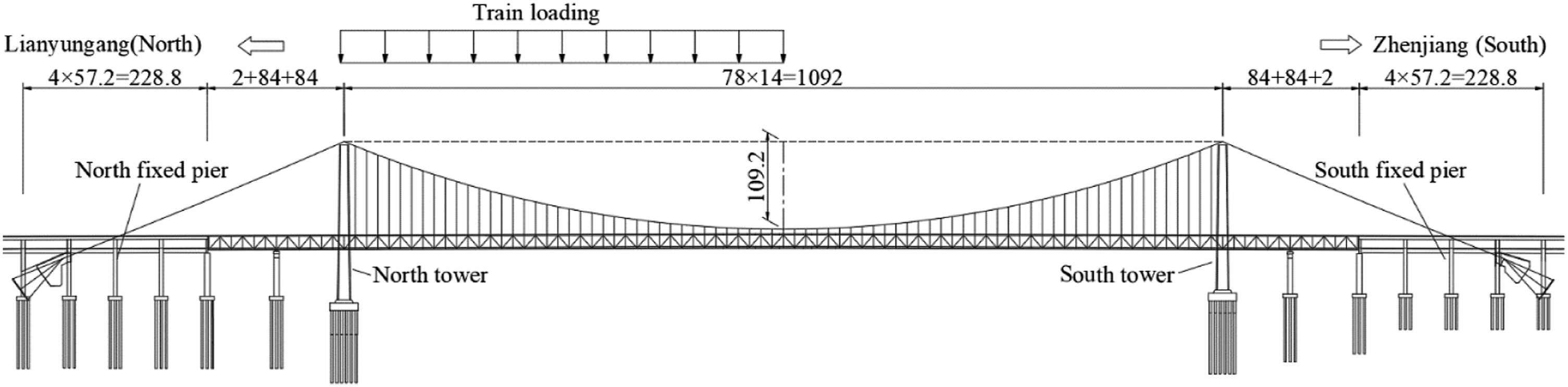
The stiffening girder of the bridge is made of a plate-truss composite steel truss. Figure 2 shows the cross section. The upper level contains eight highway lanes with a designed speed of 100 km/h, and the lower level contains four lines of passenger railways with design speeds of 250 km/h and 200 km/h. The center-to-center distance between the two main trusses is 30 m, and the height of the truss is 16 m. The road deck on the top level is 46 m in width, and the center-to-center distance between the two main cables is 43 m. The bridge uses a ballasted track structure and a type-III concrete sleeper. The rail type is CHN60 (TB/T 3276 2011). Cross section of the stiffening girder (unit: m).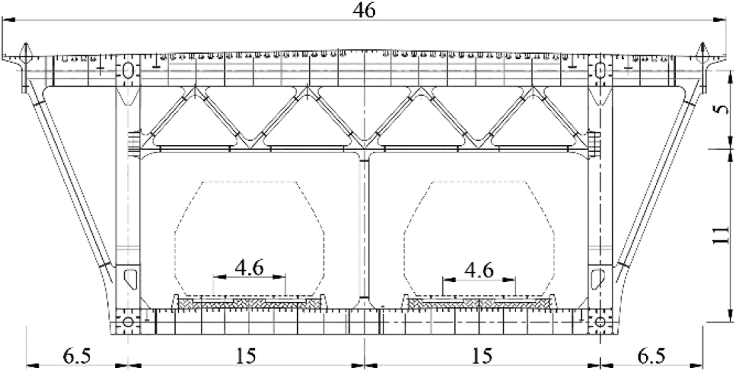
Track–bridge model of the long-span suspension bridge
A finite element model consisting of tracks, a stiffening girder, main cables, suspenders, towers, and piers is built in ANSYS. To reduce the influence of boundary conditions on the calculation results, four span-prestressed concrete continuous beams (4 × 57.2 m) and embankments (196 m) are built on both sides of the suspension bridge, and the tracks on the embankment are also established at both ends of the bridge. The boundary conditions of the tracks are set as free ends. The interference between the tracks and bridges is simulated by nonlinear springs. The constitutive law of these nonlinear springs is the resistance model, which will be introduced in the following sections. The effect of transverse displacement on the track–bridge longitudinal force is not considered in the present study. A schematic diagram of calculation model of longitudinal track–bridge interaction is shown in Figure 3. The steel truss, beams, bridge towers, piers, and rails are simulated using the beam elements BEAM4. The main cables and suspenders are simulated using the link elements LINK10. In addition, according to the design document, the lateral stiffness and vertical stiffness of the bearings of the stiffening girder are set as 3.1×10⁵ kN/m and 1.0×10⁹ kN/m, respectively. The bridge bearings are simulated by spring element COMBIN14. The elasticity modulus of the steel truss, main cables, and suspenders are defined as 2.06 × 10⁵ MPa, 1.95 × 10⁵ MPa, and 2.05 × 10⁵ MPa, respectively. The interaction between the girder and track is simulated using different types of nonlinear spring elements. For instance, the spring element COMBIN14 is used to simulate the vertical and lateral resistances of the track. The stiffness of COMBIN14 is a constant value. The longitudinal resistance of the lines is simulated by another spring element, COMBIN39. The element COMBIN39 is capable of simulating variable stiffness and hysteretic properties of the longitudinal interference between the tracks and bridge deck. The viscous dampers are simulated by the beam elements BEAM4. The equivalent stiffness of the viscous damper on the main tower is set as 7500 kN/m according to the design document. The geometric nonlinearity is taken into consideration in this model, and the main cable of suspension bridge is simulated by many elements, and the sag effect of the main cable is considered in the large displacement analysis. The expansion joints between the main bridge girder and the approach box girder are ignored; therefore, there is a 2 m wide gap. However, the rail is continuously simulated, as shown in Figure 3. In order to study the general law of track–bridge interaction, the expansion joints of the CWR are not considered and the buckling of the trail structure is not discussed in the text. The static finite element model of the suspension bridge for track–bridge interaction analyses is shown in Figure 4. Calculation model of track–bridge interaction. Finite element model of track–bridge interaction on suspension bridge.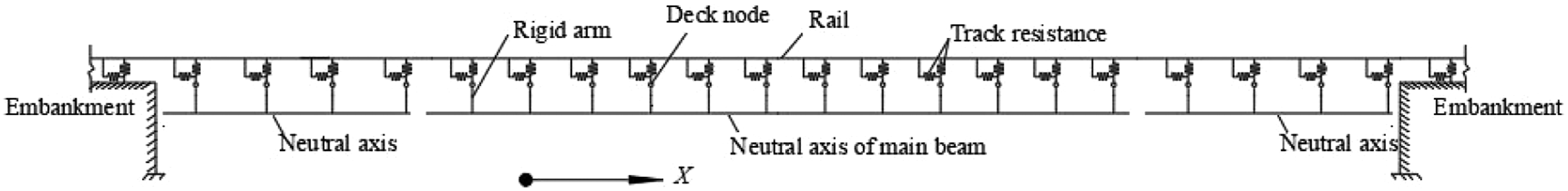

Resistance model in the code
The longitudinal resistance of the track is a key parameter in the calculation of the track–bridge interaction. The longitudinal resistance models in different nation codes are different. They can be divided into two categories: the constant resistance model and the ideal elastic–plastic resistance model. The Japanese national code uses the constant resistance model to calculate the track–bridge interaction of ballastless tracks (Yan et al., 2012). It is recommended that the longitudinal resistance of the fastener in Shinkansen is 5 kN/(mrail) (TB10015 2012, 2012). Germany (DS899/59 1991, 1991) and China utilize the ideal elastic–plastic resistance model to analyze and calculate the track–bridge interaction of ballast tracks, as shown in Figure 5. Longitudinal resistance model of ballast track (TB10015-2012, 2012).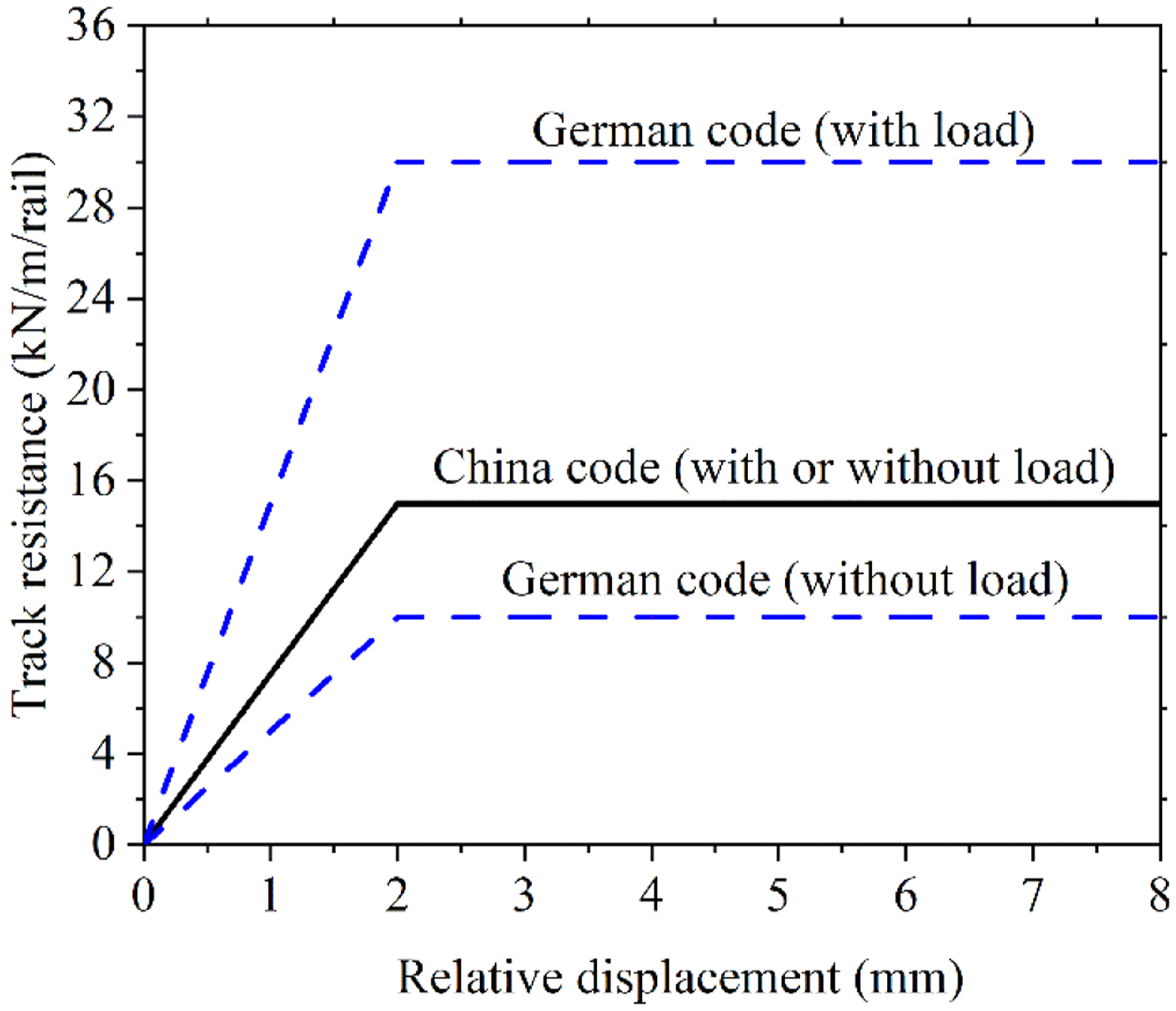
In both the German and Chinese codes, the track resistance is expressed using a bilinear model. When the TBRD is less than 2 mm, the track resistance linearly increases with the relative displacement, while when the TBRD is larger than 2 mm, the track resistance remains constant. In particular, in the German code, the maximum track resistance with and without load is 30 kN/(mrail) and 10 kN/(mrail), respectively; in the Chinese code, the maximum track resistance is 15.0 kN/(mrail) both with and without load, as illustrated in Figure 5. In the present study, the resistance model in China code is adopted to simulate the interference between the tracks and bridge.
Model validation
The FEM model of the Wufengshan Yangtze River Bridge was firstly validated by comparing the calculation results under self-weight with the design value. The results show that the displacement of the main cable and the stiffening girder is very close to the design value, and the difference is less than 0.05 mm. The difference of the internal force of the main cable and suspenders between the calculation results and design value is less than 2%. It verified that the established numerical model is accurate for track-bridge interaction analyses.
Loads and effects
Load parameters
According to the Chinese railway design code (TB10015 2012), the temperature effect of the steel truss girder of the suspension bridge and the concrete beam of the approach bridge are set as rising by 25°C and 15°C, respectively. The temperature change of the rail is ignored and the expansion rail joints are not considered in the present study. The train load is calculated according to the ZK live load of the Chinese code (equal to 0.8 UIC). ZK live load refers to high-speed railway train load in the Chinese code, and it describes the generalized expression of the static effect of trains on the bridge and expresses the size, range, and direction of the train load as Figure 6 shows (UIC 774–3R, 2001; TB/T 3466 2016). When calculating the braking force, the wheel–rail adhesion coefficient is set as 0.164 according to the code (TB10015 2012). The train load is set as 550 m in length (TB 10621 2014) on the inside double lines, and its location starts at the tower to the mid-span, as shown in Figure 1. This is the worst loading condition of the train load for rail additional force as reported by Ren (2019). The train loads include the bending load (BDL) and the braking load (BKL). The BDL refers to the vertical train load on the suspension bridge, and the BKL refers to the train brakes on the suspension bridge. The direction of the BKL is defined as the train running from north to south. ZK live load of Chinese code (TB/T 3466-2016, 2016).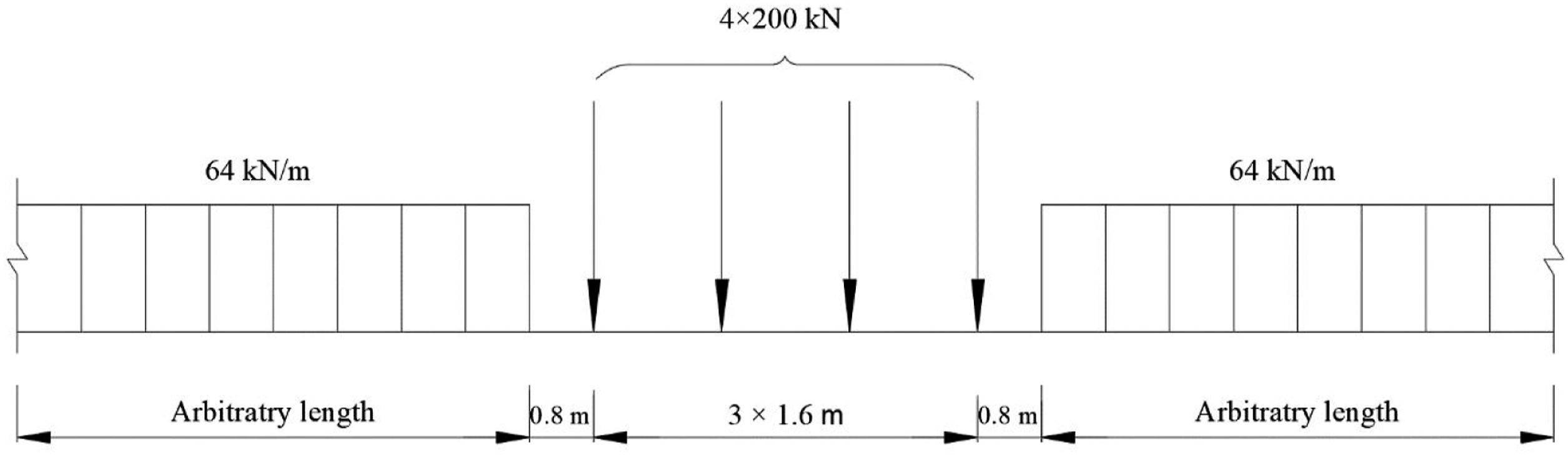
Effects
Three types of effects on the suspension bridge, including the temperature rising load (TRL), BDL, and BKL, are considered. The additional longitudinal forces on the rails, fixed pier, and the TBRD are calculated and analyzed under the actions of a single effect or multiple effects.
It is worth noting that in the following text, the case “TRL + BDL” means the combination effects of TRL and BDL. First, the interaction between the track and bridge is separately calculated under rising temperature and bending loads. Then, they are added together to represent the interaction between the track and bridge under combination of rising temperature and bending loads by linear superposition (TB10015 2012).
Additional forces on the rails under single effect and multiple effects
In this section, the additional forces are calculated under each single effect and the results are shown in Figure 7 and 8. It is worth noting that the rail position is defined as the distance far away from the centerline section of the north tower, and the southward is defined as positive as shown in Figure 1. This means that the zero point on the rail position (the horizontal coordinate) is located at the centerline of the north tower. The tension stress on the rails is defined as positive. Additional rail stress under single effect. Under a single effect: (a) longitudinal displacement of the bridge and (b) TBRD.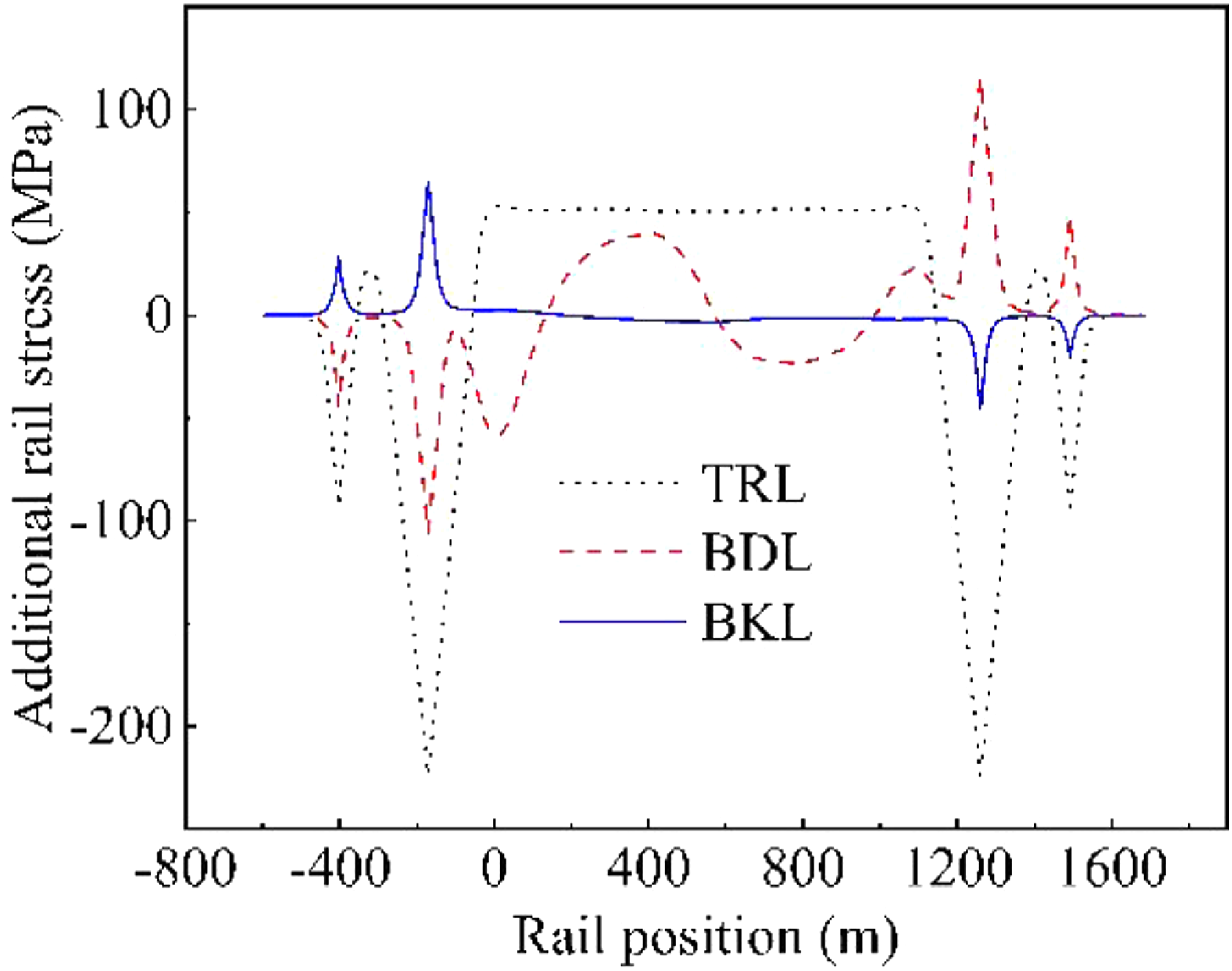
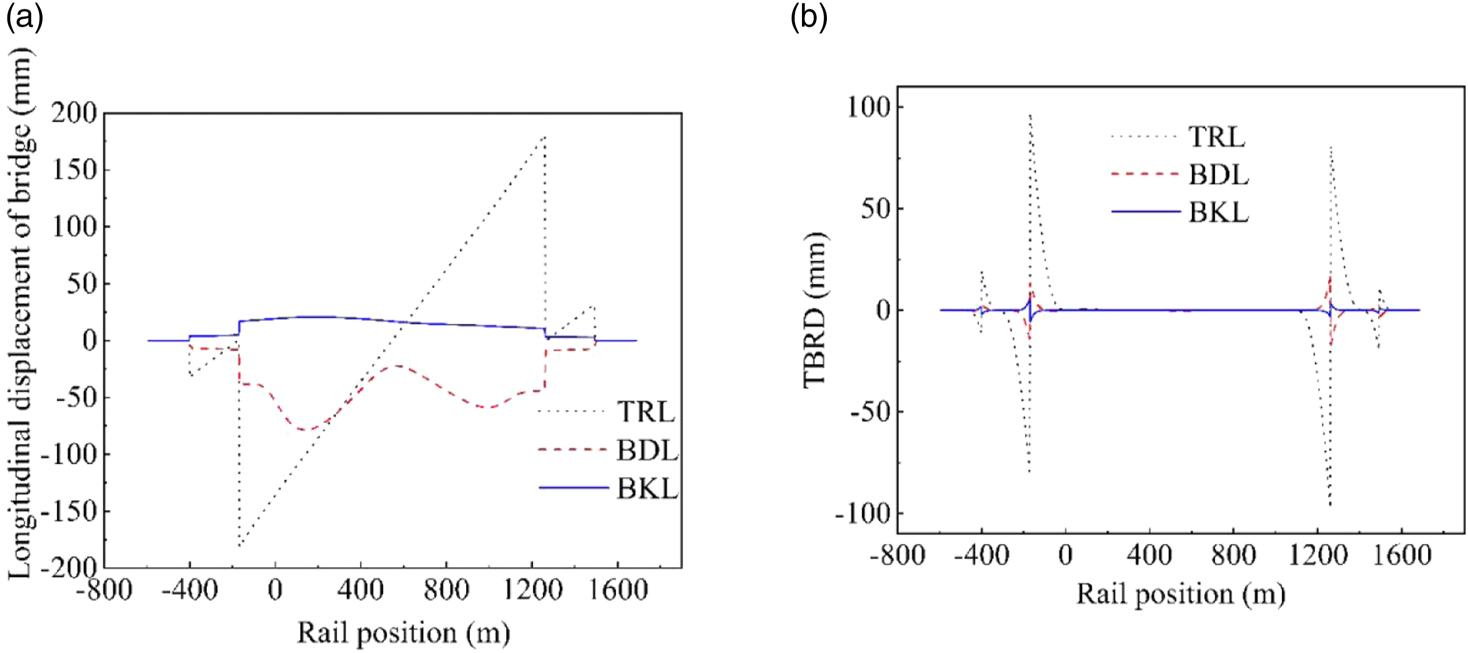
Figure 7 shows that under the temperature rising effect, the additional stress on the rail is tensile stress in the mid-span and compressive stress around both ends of the suspension bridge girder. In particular, the tensile stress is equal to 53.1 MPa at the rail position region from 0 m to 1100 m. When it moves to both sides, the tensile stress almost linearly decreases and reaches −224.0 MPa at the girder ends of the main bridge. Compared with other small- or medium-span simply supported beam bridges (Yu et al., 2018) or continuous beam bridges (Xu and Chen 2006), the additional temperature stress on the rail is obviously larger on this long-span suspension bridge. Compared with a cable-stayed bridge (Wang et al., 2013), the longitudinal distribution of additional rail stress on the suspension bridge is relatively similar.
Figure 8 shows the longitudinal bridge displacement and the relative longitudinal displacement between the track and bridge under a single effect. Under the temperature rising effect, the longitudinal displacement of the girder is anti-symmetric against the mid-section of the main bridge. As the bridge extends to both sides under the temperature rising effect, the longitudinal displacement linearly increases from the mid-span to both sides. The maximum longitudinal displacement of the bridge is equal to 180 mm at both ends of the bridge girder. The relative longitudinal displacement between the track and bridge of the main bridge is equal to zero in the mid-region of the main bridge, from 0 m to 1100 m, and linearly increases at both ends due to the constraint of the CWR. The maximum TBRD at both ends of the main bridge is 97.2 mm. Because the bridge girder extends under the temperature rising effect, it tensions the rails and makes the rails have tension stress on the mid span of the main bridge. As the rail expansion is constrained, the rail is subjected to compressive stress at both ends of the main bridge.
When the train load is added onto the bridge, as shown in Figure 1, the bending load in the main girder and the rails generates additional stress on the rail, as shown in Figure 7. From the north tower southward, the stress on the rail gradually varies from compressive stress to tensile stress in the loading region. Then, the stress on the rail gradually returns to compressive stress. The maximum tensile stress is approximately 40.04 MPa at the 400 m section. As the train is loaded on one side, the stress distribution is nonsymmetric. Similar to the temperature effect, the additional stress on the rail suddenly changes at both ends of the girder due to the different boundary conditions of the girder and the rail. Extreme additional stress appears at both ends of the girder. In particular, the extreme compressive stress and tensile stress on the rail are 105.9 MPa and 115.1 MPa at the north and south ends of the main bridge, respectively.
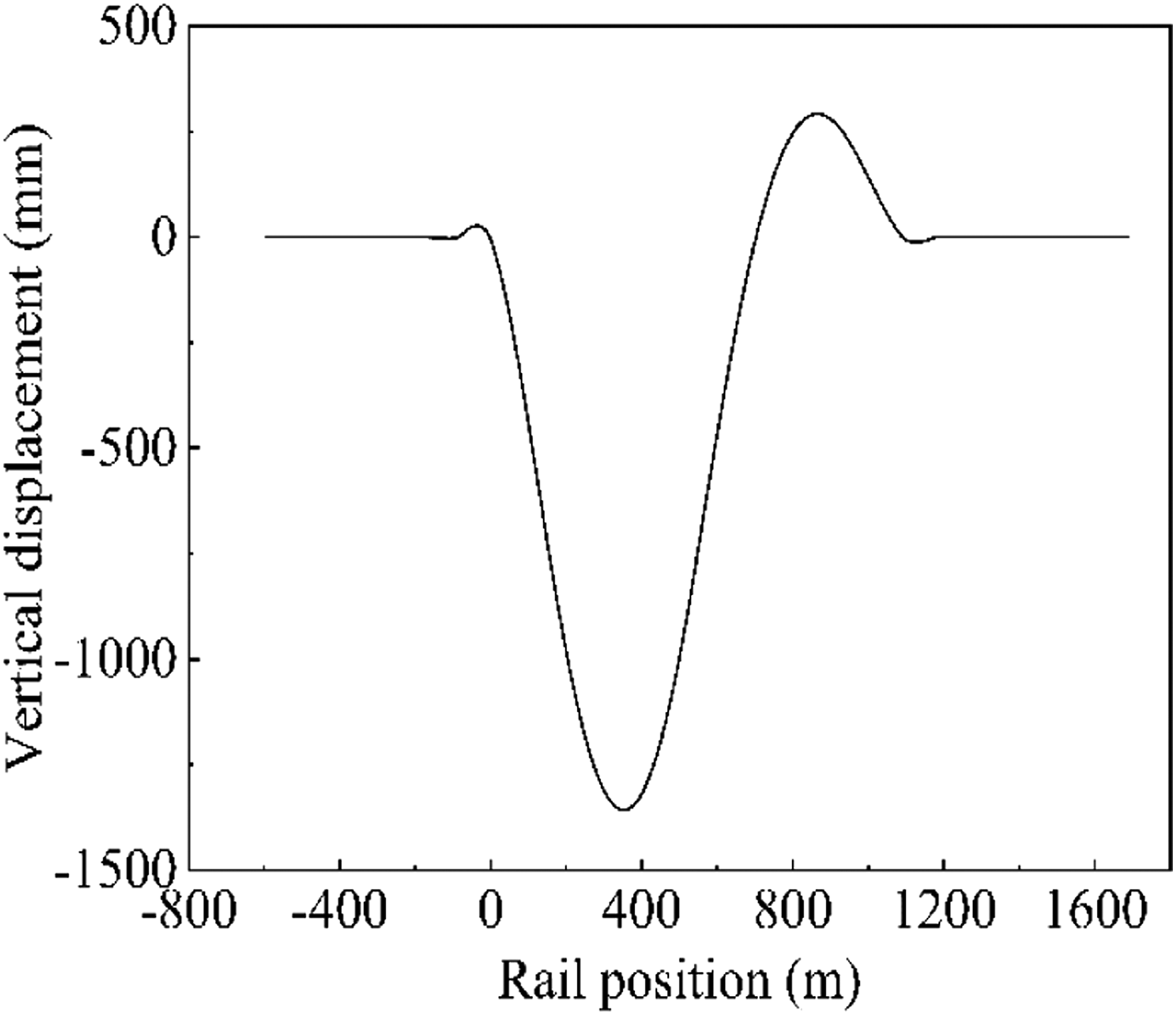
Under the bending load, the longitudinal displacement of the bridge is northward, and the extreme displacement reaches 78 mm, as shown in Figure 8(a). The relative longitudinal displacement between the track and the bridge on the main bridge increases at both ends due to the constraint of the CWR and is less than 1 mm in the mid-region of the main bridge from −110 m to 1200 m. The extreme TBRDs at both ends of the main bridge are 14.17 mm and 16.33 mm. The relative longitudinal displacement changes its sign in the mid-region of the main bridge. The compressive stress turns to tensile stress from the tower centerline to the 400 m section. The comparison of the TBRD and the additional rail stress under the bending load are shown in Figure 9. This confirms that the additional stress on the rail depends on the TBRD under bending load. The TBRD is equal to zero at the 400 m section, where the resistance force reverses. The vertical deformation distribution in Figure 10 shows that the maximum vertical displacement is equal to −1357 mm at the 400 m section. Distribution of the TBRD and stress of the main bridge under the bending load. Vertical displacement under the bending load.
Compared with the temperature effect, the effect of the bending load is relatively slight. The additional stress and the relative longitudinal displacement caused by the bending load of this long-span suspension bridge are obviously higher than those for small- or medium-span bridges (Xu and Chen 2006; Yu et al., 2018).
Under the braking load effect, the additional stress on the rail of the north side of the main bridge is tensile stress and that of south side is compressive stress. The extreme additional stresses are 64.6 MPa and −45.4 MPa, respectively. In particular, on the main span, the additional stress on the rail is very slight, at only 3.0 MPa in the region from −100 m to 1200 m. The longitudinal displacement of the bridge is southward because the bridge extends toward the south under the braking load. The maximum value is 20.6 mm. The relative longitudinal displacement between the track and bridge of the main bridge is equal to zero in the mid-region of the main bridge, from 0 m to 1100 m, and linearly increases at both ends due to the constraint of the CWR. The extreme TBRDs at both ends of the main bridge are −5.5 mm and −3.1 mm. Because the longitudinal TBRD under the braking load in the mid-region of the main bridge is very small, the additional stress on the rail is also very slight in this region. At both ends of the main bridge, as the bridge extends to the south side, the rail is subjected to tensile stress on the north girder end and compressive stress on the south girder end.
Compared with the effects of temperature and bending stress, the braking stress has a much smaller effect on the mid-region of the main bridge. In addition, the additional stress of this long-span suspension bridge is lower than that of small- or medium-span bridges (Xu and Chen 2006; Yu et al., 2018).
The additional force on the rails under the combination effects are calculated and shown in Figure 11. For Case “TRL+BDL,” the extreme additional tensile stress in the mid-span reaches 90.7 MPa, and the highest compressive stress is 329.9 MPa at the north girder end of the main bridge. For Case “BDL+BKL,” the additional stress in the mid-span of the main bridge reaches 70.1 MPa, much lower than that of Case “TRL+BDL.” For Case “TRL+BDL+BKL,” the additional stress curve is similar to that of Case “TRL+BDL.” However, the maximum compressive stress is reduced by approximately 20% because the braking load effect is opposite to those of the temperature and bending load. Additional rail stress under multiple effects.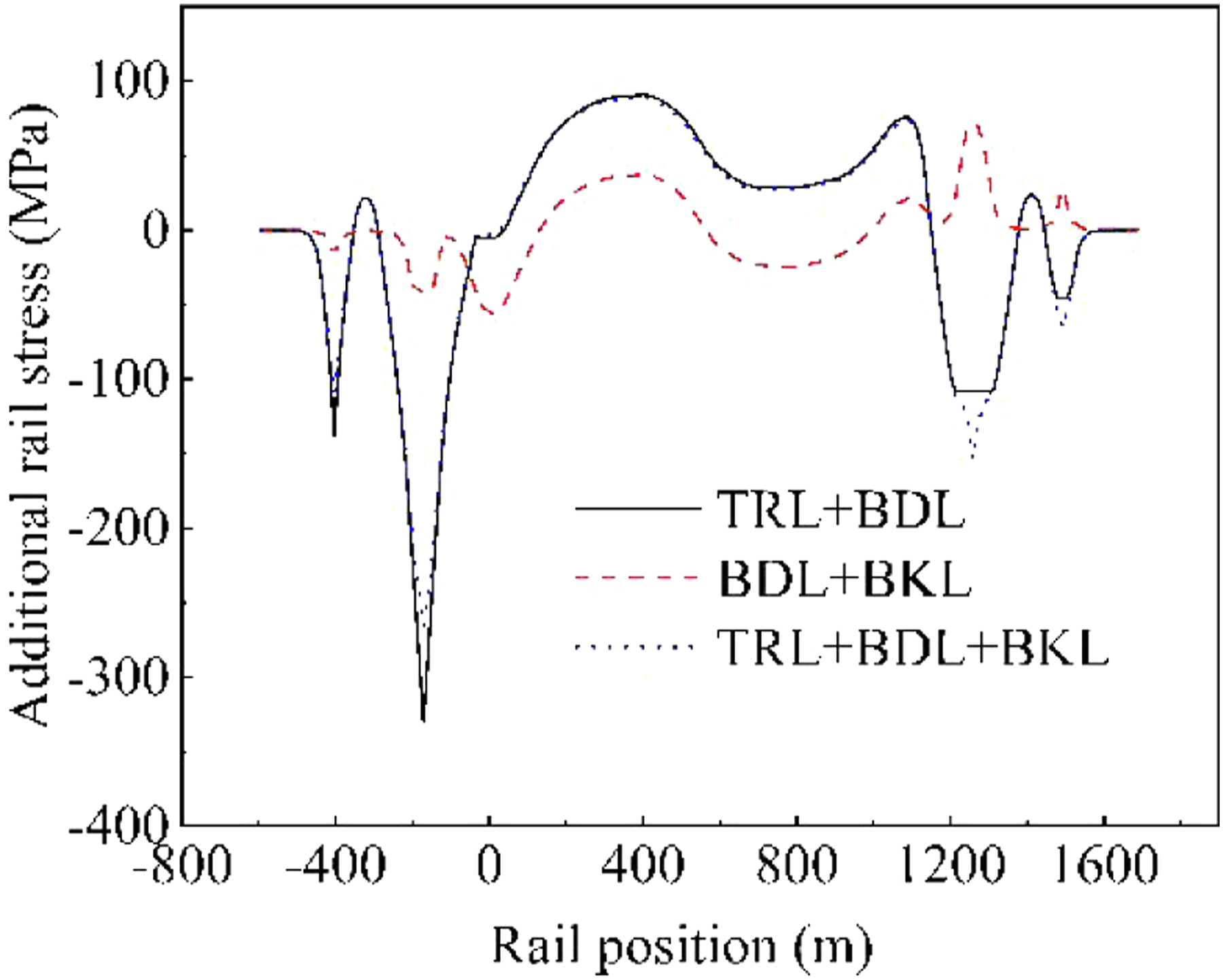
Extreme additional stress and extreme horizontal force at the pier top
Extreme rail stress and horizontal force at the pier top.
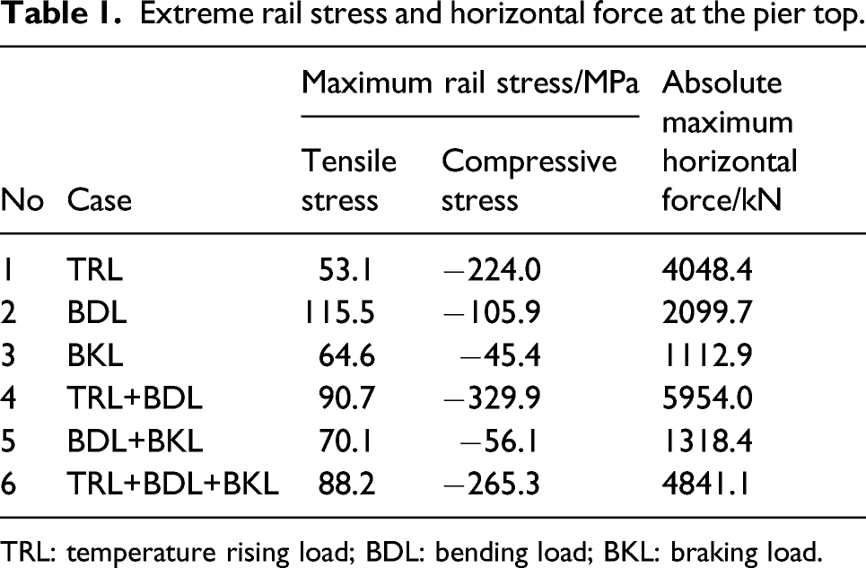
TRL: temperature rising load; BDL: bending load; BKL: braking load.
The analyses show that the temperature effect dominates the calculations of track–bridge interactions for large-span suspension bridges. According to previous engineering experience, to address the large temperature force at the girder end of a long-span bridge, rail expansion joints should be added at the girder end (Cai et al., 2018).
Conclusions
This paper investigates the track–bridge interactions of the Wufengshan Yangtze Bridge through numerical simulations. The longitudinal additional forces of the track under a single effect and combination effects of temperature rising load, bending load, and braking load are calculated using linear superposition method. The main conclusions are drawn as follows: (1) There are strong additional forces on the CWR of the Wufengshan Yangtze Bridge under the temperature rise, train loading, and train braking effects. (2) The maximum tensile stress is 115.5 MPa in Case BDL, and the extreme compressive stress reaches 329.9 MPa in Case TRL+BDL; the highest additional force on the rail always appears around both ends of the stiffening girder due to the different boundary conditions of the bridge and CWR. (3) The temperature rising load dominates the additional forces of the rail on this long-span suspension bridge; the maximum longitudinal displacement of the bridge reaches 180 mm at both ends of the bridge girder; and the maximum track–bridge relative displacement at both ends of the main bridge is 97.2 mm. (4) Rail expansion joints are needed for this long-span suspension bridge.
Footnotes
Declaration of Conflicting Interests
The author(s) declared no potential conflicts of interest with respect to the research, authorship, and/or publication of this article.
Funding
The author(s) disclosed receipt of the following financial support for the research, authorship, and/or publication of this article: This research was financially supported by the National Natural Science Foundations of China (52078502).