
Abstract
In the present paper, a comprehensive study on the flexural fatigue behavior of ultra-high-performance concrete (UHPC) beams prestressed with carbon-fiber-reinforced polymer (CFRP) tendons is reported. A total of two UHPC beams prestressed with CFRP tendons were experimentally investigated. On the basis of the fatigue constitutive model of the materials, a fatigue prediction model (FPM) was developed to simulate the flexural fatigue evolvement of the beams. The strain and stress in UHPC and CFRP tendons were calculated by the sectional stress analysis. The influence of steel fiber was considered in the formulae for the crack resistance and crack width, and the midspan deflection was calculated using the sum of deflection before cracking and increment after cracking. The obtained test results were used to verify the FPM. A parametric study was then conducted to analyze the fatigue development of such component, and a formula to predict the flexural fatigue life of UHPC beams under different fatigue loads was proposed.
Keywords
Introduction
Carbon-fiber-reinforced polymer (CFRP) materials are now used in extensive structural applications due to their high strength, good fatigue resistance, and excellent ability to withstand corrosion (Fang et al., 2013; Peng et al., 2016). However, normal-concrete structures reinforced with CFRP generally exhibit limited ductility, because of the elastic-brittle property of CFRP. Therefore, ultra-high-performance concrete (UHPC) with high strength and large ultimate compressive strain can be introduced to form CFRP-reinforced UHPC structures with preferable ductility. UHPC has the advantages of high compressive strength, favorable strength-to-weight ratio, good ductility, and remarkable durability (Wang and Belarbi, 2010). High-strength material UHPC reinforced with high strength material CFRP can have high bearing capacity, excellent durability, and favorable ductility (Ghafoori et al., 2012; Huang et al., 2017; Xie et al., 2012). Furthermore, the coarse aggregate is not contained in UHPC, which is hopeful to be produced by seawater and sea sand to save fresh water resources and transportation costs in the remote marine engineering (Da et al., 2017). Considering the corrosion problem in the seawater environment, CFRP reinforcement would be an excellent option. The CFRP-reinforced UHPC structure will have broad application prospects, particularly for structures in harsh conditions (Cheng 2011; Larson et al., 2005; Oudah and El-Hacha, 2013b).
Nevertheless, because of the application of high-strength materials, the sectional dimension of the structural members and self-weight of the structure will be effectively reduced (Hu et al., 2021). The proportion of the live load effect in the structure significantly increases, which leads to the increase in live load stress amplitude of the component (Charalambidi et al., 2016; Yang et al., 2019; Zhu et al., 2018). Thus, the fatigue behavior of UHPC beams prestressed with CFRP tendons is a crucial issue that should be addressed (Fang et al., 2020; Ferrier et al., 2011; Harries and Aidoo, 2006).
However, as a promising structure, only few aspects of the performance of the UHPC component reinforced with CFRP tendons have been investigated. Yang and Fang (2015) investigated the ductility and deformability of UHPC beams prestressed with CFRP tendons. The beams had better deformation capacity than normal concrete beams with the identical reinforcement. Ghasemi et al. (2016) conducted flexure tests and punching shear tests of a waffle deck consisting of UHPC and CFRP bars. Such deck exhibited good ductility and was not susceptible to punching shear failure. Other studies mostly focused on the anchorage behavior or bond performance between UHPC and CFRP tendons (Ghasemi et al., 2016; Firas et al., 2011) or the UHPC component strengthened with CFRP laminate (Chen and El-Hacha, 2013; Cheng, 2011; Garner, 2011; Genedy, 2014; Kromoser et al., 2018; Meng et al., 2018). Until now, public reports on the fatigue behavior of UHPC beams reinforced with CFRP tendons remain scarce.
To predict the fatigue evolvement of concrete structures reinforced with CFRP tendons, some fatigue prediction models were developed. Noël and Soudki (2014a; 2014b) proposed a fatigue model to predict the fatigue deflection, crack width, and fatigue strength of slab strips with a reinforcement system combining passive GFRP (Glass-Fiber-Reinforced Polymer) bars and active CFRP tendons. Elrefai et al. (2012) developed a fatigue model to predict the fatigue life of reinforced concrete beams strengthened with externally post-tensioned CFRP tendons. The local stresses and strains instead of the average stresses in the steel bars were considered in the fatigue model. All of these fatigue prediction models are useful in the design process or reliability analyses for normal concrete structures reinforced with CFRP tendons, but no fatigue prediction model for UHPC beams prestressed with CFRP tendons has been established.
Therefore, the present study aims to develop a fatigue prediction model (FPM) to predict the fatigue evolvement of UHPC beams prestressed with CFRP tendons and provide references for engineering design (Oudah and El-Hacha, 2013a). Fatigue constitutive models of UHPC and CFRP tendons in the literature and three fundamental assumptions were used in the developed FPM. The strain and stress in UHPC and CFRP tendons were calculated by sectional stress analysis, which lays the foundation for the simulation of the midspan deflection and crack width of the UHPC beams. The midspan deflection of the beam is calculated by the sum of deflection before cracking and the increase in deflection after cracking to consider the cracks along the UHPC beam. Formulae for the crack resistance and crack width were also proposed in the FPM. Two UHPC beams prestressed with CFRP tendons were tested under flexural loading to verify the proposed FPM, and a parametric study was conducted using the verified FPM to analyze the fatigue evolvement of such component under different fatigue loads. Based on the regression analysis, a formula to predict the fatigue life of the beam was proposed, and the upper limit of the fatigue load amplitude under 2 million times of cyclic loading was suggested for the UHPC beam prestressed with CFRP tendons.
Fatigue constitutive models of the materials
Fatigue constitutive model of UHPC
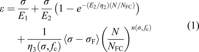
The fatigue strain evolvement of UHPC exhibits three stages under high stress levels. The strain in UHPC quickly develops in the first stage and remains steady in the second stage. In the third stage, the strain in UHPC rapidly increases, and the UHPC fails after fewer load cycles (Yu et al., 2010). Note that concrete fatigue and concrete creep have similar deformation development along with cyclic number or time. Both fatigue and creep phenomena have a critical stress. When the maximum stress is lower than the critical stress, two development stages exist, including rapid development stage and stable development stage. When the maximum stress is higher than the critical stress, the whole three development stages appear. The concrete fatigue can be considered as accelerated creep, and the prediction of fatigue and creep can use a single constitutive framework (Xiang and Fang 2016). Thus, a fatigue constitutive model based on the visco-elastic-plastic theory is adopted in this study to simulate the fatigue behavior of UHPC. A series of uniaxial compressive fatigue tests on UHPC prisms was conducted by Xiang and Fang (2016) and Xiang (2017), and a fatigue strain prediction model of UHPC material under cyclic loading (N) was developed based on the visco-elastic-plastic theory, as shown in equation (1)


The fatigue modulus of UHPC (Ef c) at any loading cycle can be determined from equation (1), as shown in equation (8)

The fatigue modulus of UHPC from equation (8) is presented in Figure 1. The fatigue modulus evolvement of UHPC varies with the maximum stress in UHPC. If the maximum stress in UHPC is less than its fatigue strength, only two stages of fatigue evolvement will occur. When the maximum stress in UHPC exceeds its fatigue strength, the fatigue modulus will rapidly decrease when N > 0.6NFC, and all three stages of fatigue evolvement will occur. Fatigue modulus evolvement of ultra-high-performance concrete under different stress.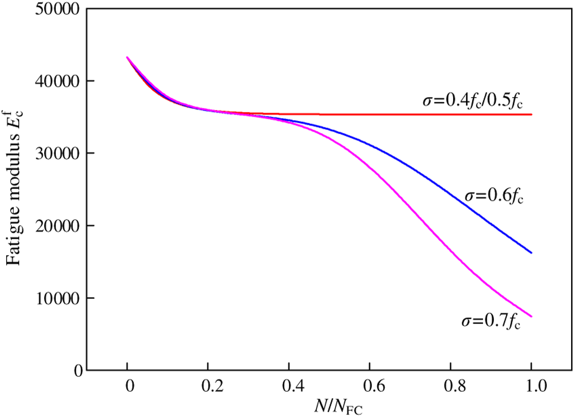
Yu et al. (2010) studied the fatigue damage accumulative behavior of UHPC. It was found that UHPC would be seriously damaged when the residual strain in UHPC (εres) reached 974 × 10−6, that is, 36% of the strain at the peak compressive stress (ε0). Moreover, this relationship is independent of the load amplitude and loading history of UHPC. Thus, εres = 0.36ε0 is taken as a criterion to determine whether the fatigue failure of UHPC occurs.
Note that before the cracking of the beam, the tensile strength of UHPC is considered in the calculation. In such condition, UHPC material is still in the elastic range, and the tensile fatigue modulus is taken as the same with the compressive fatigue modulus. However, after cracking, the steel fibers will sustain cyclic tension, cyclic compression, or cyclic shear because of their disordered distributions. The steel fibers are easy to fail or be pulled out under such condition. Thus, the tensile strength of UHPC is not considered in the calculation of the cracked beam.
Fatigue constitutive model of CFRP
The fatigue property of CFRP tendon is considered in the analysis. Ferrier et al. (2011) found that the stiffness of CFRP decreased with the increase in cyclic loading, as expressed in equation (9), which is normally adopted in the fatigue analysis of CFRP material

Adimi et al. (2000) tested the fatigue life of CFRP tendons under different stress levels and proposed the relationship between the fatigue life and the maximum stress in CFRP. However, this formula did not consider the effect of the minimum stress in CFRP and could not be applied to CFRP tendons in different stress ranges. To explore the relationship between the fatigue life and the stress range, a regression analysis was conducted based on the test results of Adimi et al. (2000), as plotted in Figure 2. The fatigue life of CFRP tendons can be predicted using equation (10). The stress amplitude in the CFRP tendon should not exceed 31.1% of its tensile strength if the fatigue life must exceed 2 million cycles. This conclusion is consistent with the experimental results in Adimi et al. (2000) Fatigue life of carbon-fiber-reinforced polymer tendons in different stress ranges.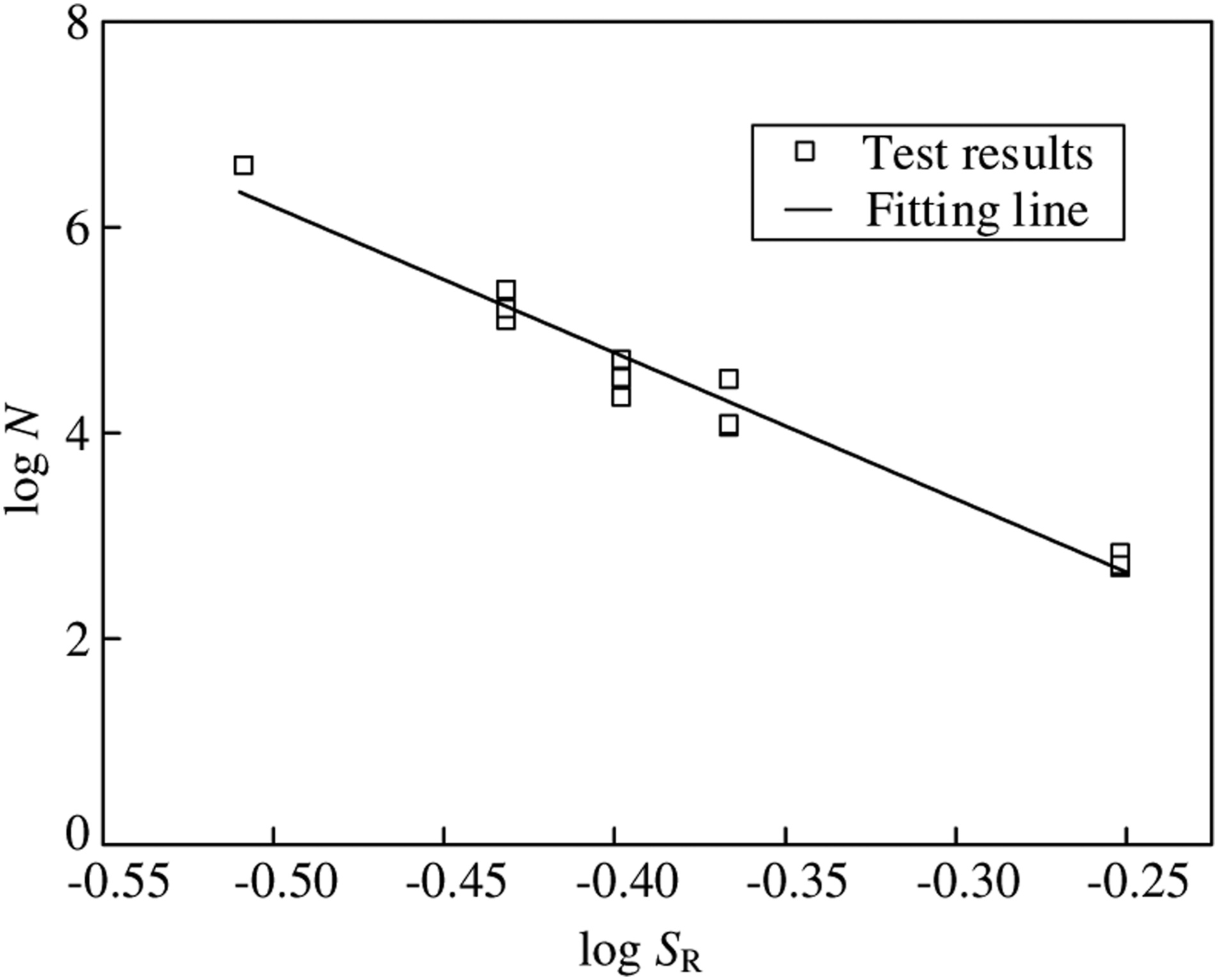

Fatigue Prediction Model
Strain and stress in UHPC and CFRP tendons
The calculation for the fatigue strain and stress in UHPC and CFRP tendons is the fundamental analysis of the fatigue behavior of UHPC beams prestressed with CFRP tendons. The depth of the compressive zone (x) and fatigue modulus of UHPC (
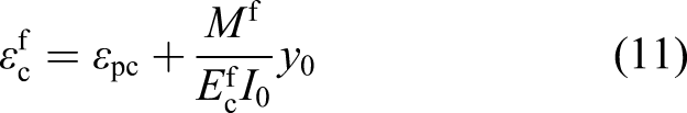
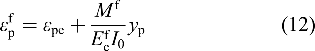
Before cracking, the strain in UHPC and CFRP tendons under moment Mf can be directly calculated using equations (11) and (12). Technically, the fatigue modulus of UHPC is different along the height of the cross-section because of the triangular distribution of the stress in the compressive zone. However, in the proposed FPM, the fatigue modulus of UHPC in the entire section is conservatively taken as that of UHPC at the top surface of the cross-section at midspan. This method will lead to a higher value of strain and stress in UHPC but simplify the calculation process
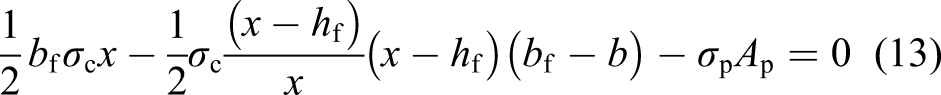
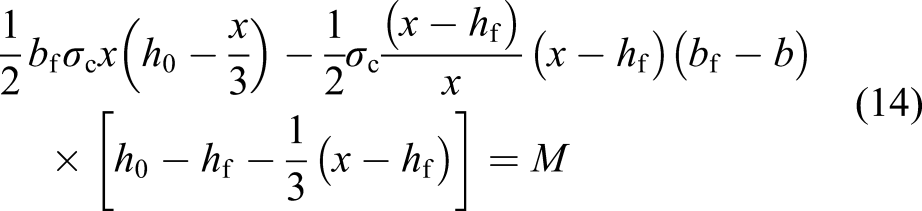
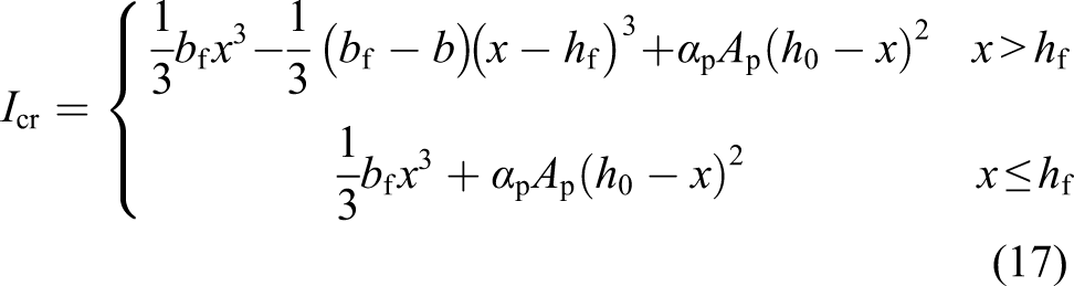
After cracking, the schematic diagram of the cross section is shown in Figure 3. The depth of the compressive zone (x) and compressive stress strain in UHPC at the top surface of the cross-section at midspan (σc) can be obtained by equilibrium equations, as shown in equations (13)–(14) Schematic of the cross section after cracking.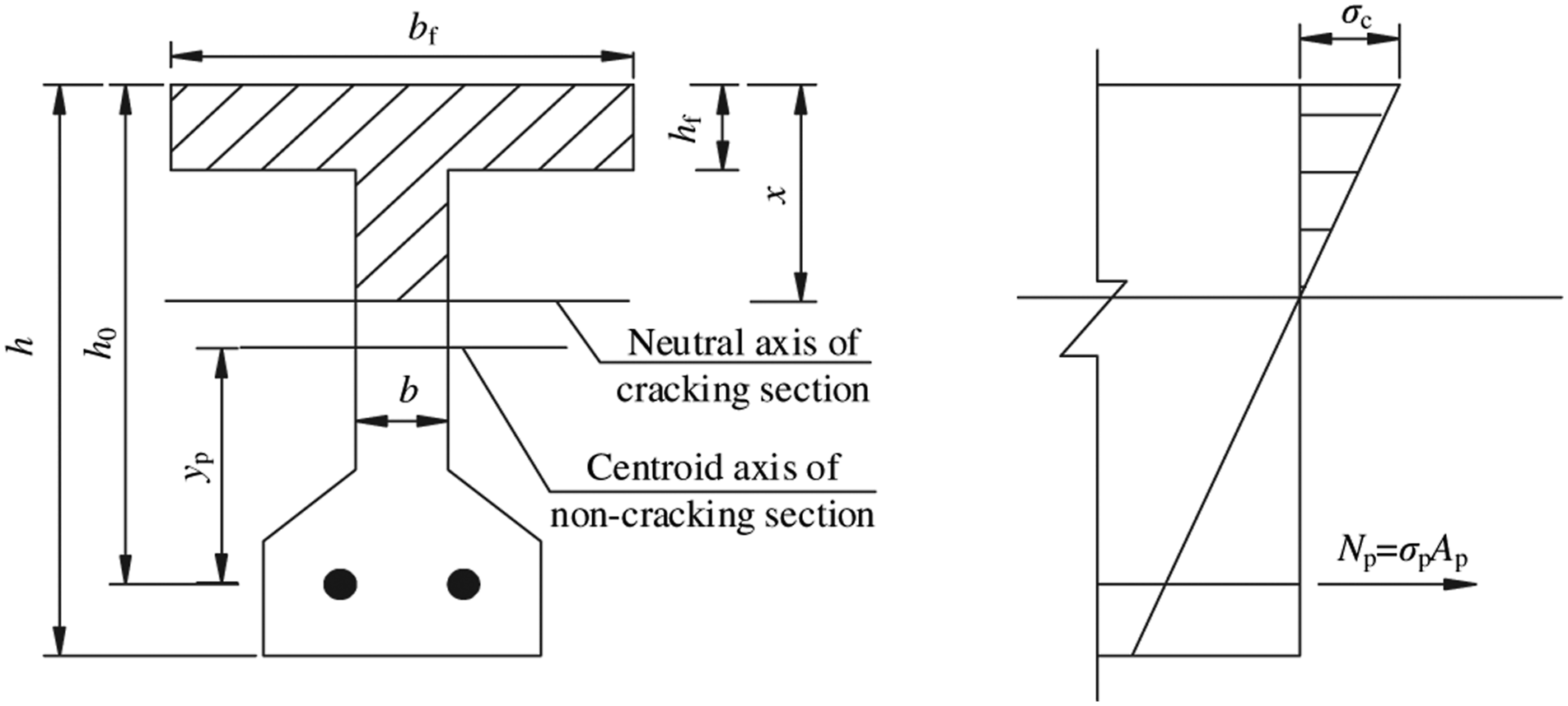
If the neutral axis of the cracked section passes through the flange of the T-shaped section, b can be taken as bf in equations (13) and (14).
Midspan deflection
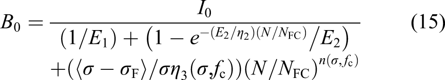
The midspan deflection or stiffness of the beam is an important macroscopic index of the response of UHPC beams and can be used to evaluate the fatigue damage of UHPC beams (Xie et al., 2012). The flexural stiffness of the section before cracking is given by equation (15)
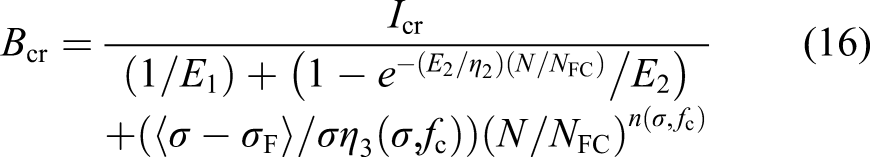
The flexural stiffness of the cracked section can be written as
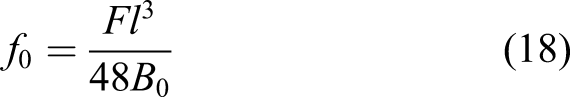
The midspan deflection of the beam under three-point loading before cracking is
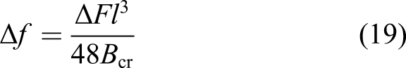
When the moment at midspan exceeds the crack resistance, the sectional stiffness changes from B0 in the uncracked section to Bcr in the cracked section, as shown in Figure 4. The midspan deflection calculation for the cracked beam is based on the minimum stiffness assumption. The flexural stiffness of the section in the entire beam is taken as that of the section with maximum moment. The deviation of calculation results caused by the minimum stiffness assumption was acceptable (Du and Au, 2014), and the calculated fatigue deflection based on the minimum stiffness assumption agreed well with the test data. Thus, the deflection increment of the beam after cracking is Calculation of the deflection of the cracked beam.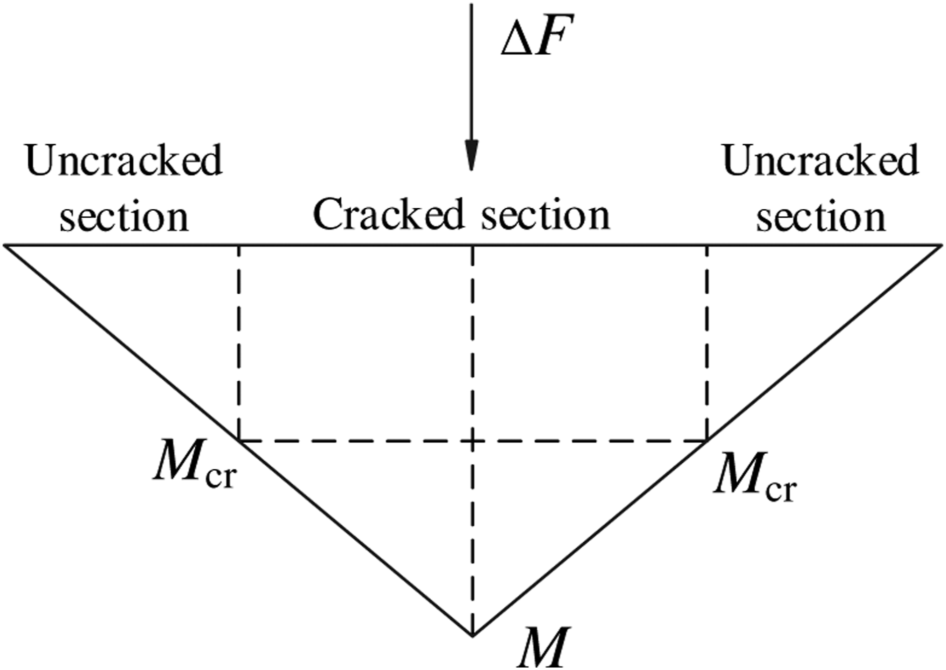
Thus, the total deformation of the beam is expressed as

Crack resistance
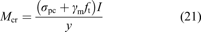
The calculation method for strain and stress in the materials and deflection of the beam is different before and after cracking. The calculation for the cracking resistance of the beam should be contained in the FPM. The cracking bending moment (Mcr) of the prestressed UHPC is
The plastic influence coefficient (γm) is calculated on the analysis of the plain UHPC components. When the UHPC beam is about to crack, the stress in UHPC on the lower edge of the cross-section reaches its tensile strength. The plastic deformation will occur in a certain range of the cross section because of the reinforcement of steel fibers in UHPC. The calculation model for crack resistance is presented in Figure 5. According to Lok and Xiao (1998), the tensile secant modulus of UHPC at the ultimate tensile strain is half of the initial tangent modulus. Thus, the strain and stress distributions on the cross-section are presented in Figure 5(b) and (c), respectively. Based on the simplified model, as shown in Figure 5(d), and the equilibrium condition of the section, we can obtain Calculation model for the crack resistance. (a) Tensile stress–strain relationship of ultra-high-performance concrete, (b) strain distribution, (c) stress distribution, and (d) simplified model.
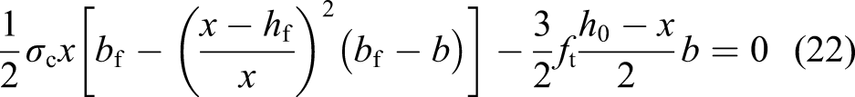

Substituting the specific dimensions into equations (22)–(23), the depth of the compressive zone (x) can be solved from equation (22). Substituting x into equation (23), the plastic influence coefficient (γm) of UHPC in tension in this study can be obtained as 1.51.
Crack width
The prestressed concrete structures are usually applied in the engineering where crack development is strictly limited. The maximum crack width under fatigue load must also be calculated in the FPM for UHPC beams prestressed with CFRP tendons. The maximum crack width formula for normal concrete structures was proposed by Gergely and Lutz (1968)

To calculate the crack width of the UHPC structures, the steel fiber influence coefficient (βcw) is introduced, as shown in equation (25)
Considering different modulus between CFRP tendon and steel bar, the crack width of the UHPC structures prestressed with CFRP tendons can be calculated by equation (26). The correction coefficient of 1.8 is used for the prestressed concrete structures without non-prestressed reinforcement, considering the differences in bond performance between prestressed tendons and non-prestressed steel bars (Du, 1988)
Because of the good bond performance between CFRP tendons and UHPC, the crack width of the beam can be assumed to be in proportion to the strain increment in CFRP tendons (Fang et al., 2007; Firas et al., 2011). The fatigue crack width can be written as equation (27)

Experimental program
Test specimens
The dimension and reinforcement of the tested beams are shown in Figure 6. Except for two CFRP prestressing tendons in the tension area of the beam, no rebars were arranged in the specimen. Note that shear tests of the beam were conducted in another experiment, and the maximum shear load of the tested beam was measured as 167 kN (Fang et al., 2020). The theoretical flexural strength of the beam can be calculated based on the plain section assumption, and the calculated flexural bearing capacity is 113 kN, which is less than tested maximum shear load. Thus, the two specimens presented in this study were designed to exhibit flexural failure. Dimension and reinforcement of the specimen (units: mm). (a) Cross section and (b) lateral view.
A pretension system, including hydraulic jacks, concrete sump, spreader beam, and strand tapered anchorage, was used to prestress the CFRP tendons, as shown in Figure 7 (Fang et al., 2020). The prestress of the CFRP tendons was conducted one day before the casting of the UHPC beams. The prestressing load applied on one CFRP tendon was 84 kN. The strain gauges were attached to the CFRP tendons, and LVDTs were set beside the hydraulic jacks, in order to measure the tensile strain and elongation in CFRP tendons, respectively. UHPC was then poured into the mold and the beam was demolded after 24 h. Afterward, the beams were cured for 48 h in 80 ± 2°C hot water and gradually cooled for another 48 h in the concrete sump. The UHPC cubes and prisms used for material property test were similarly cured under the same condition as the test specimens. Pretension system (units: mm).
The CFRP tendons outside the beams were cut at 8 days after the casting, and the prestress was transferred to the UHPC beams. The prestress in CFRP tendons and effective precompression stress at the bottom of the beam after the tendon release were measured by the strain gauges on the tendons and bottom surface of the beams. The resultant stress in one CFRP tendon after the release was measured as 955 MPa. Finally, the beams were stored in the laboratory until the test day.
Mechanical properties of the material.

Note: fcu = compressive strength of standard 100-mm UHPC cubes; fc = compressive strength of 100 mm × 100 mm × 300 mm UHPC prisms; fts = splitting strength of standard 100-mm UHPC cubes; ftu = tensile strength of UHPC, converted from the splitting strength (ft = 0.75fts); ftf = tensile strength of CFRP; Ef = elastic tensile modulus of CFRP.
Test setup and procedure
The specimens were loaded by the PMS-500 digital display pulsation fatigue testing machine. The loading devices are presented in Figure 8(a). The static test was performed to specimen BF-S to determine the static bearing capacity, and BF-F was subjected to the constant-amplitude fatigue test. The test setup photo is shown in Figure 8(b). Loading device of the fatigue test. (a) Scene photo of the experiment and (b) sketch of the loading device.
The initial static test was first performed for specimen BF-F with increasing loading from zero to the upper limit of the fatigue load, which was set to be 65% of the static bearing capacity. The mid span deflection, crack width, strain in UHPC, and CFRP tendons under every level of loads were measured. Then, the fatigue load with the frequency of 5 Hz was applied. To ensure that relative displacement would not occur between the actuator and the distributive girder, the lower limit of fatigue load was set to be 40% of the upper limit load or 26% of the static bearing capacity. When a specimen did not fail at the number of loading cycles, 10 thousand, 50 thousand, 0.1 million, 0.3 million, 0.5 million, or 1.5 million, the above-mentioned static test was repeated. If the specimen did not fail at 2 million cycles, the specimen was statically loaded until it failed.
Experimental phenomenon
Both specimens exhibited the bending failure mode, as shown in Figure 9. Specimen BF-S was tested under static load. Vertical flexural cracks were observed when the load reached 62 kN, and flexural failure appeared under the load of 110.8 kN, as shown in Figure 9(a). Failure modes of specimens. (a) BF-S and (b) BF-F.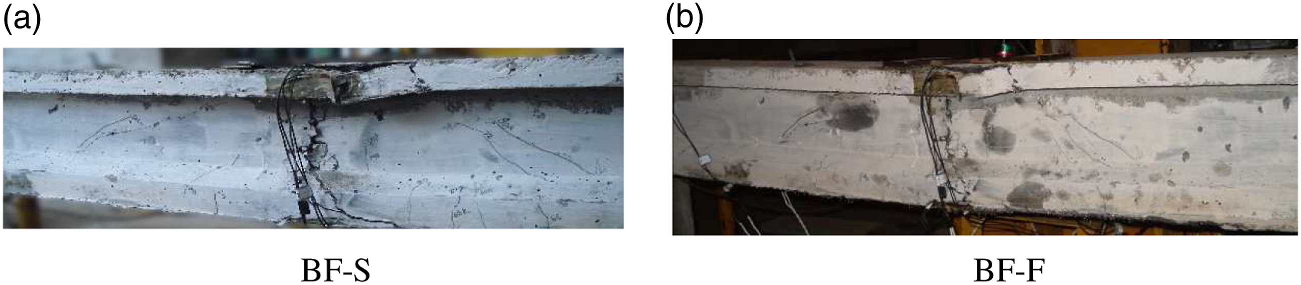
The specimen BF-F was initially tested under static load up to 72 kN, 65% of the static ultimate load of 110.8 kN. Initial vertical cracks were observed when the static load reached 68 kN. The maximum width of the initial vertical crack was 0.05 mm under the static load of 72 kN. At 2 million cycles, the maximum width of initial vertical crack reached 0.08 mm, and the specimen did not fail. Then, the static load was applied, and the UHPC at the upper edge of the cross section at midspan of specimen BF-F was crushed when the static load reached 112 kN, as shown in Figure 9(b).
Test results of the specimens.
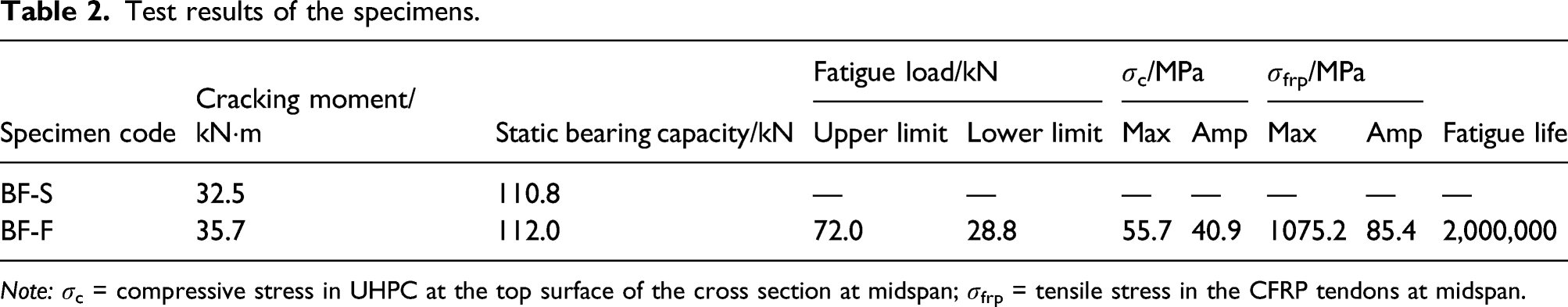
Note: σc = compressive stress in UHPC at the top surface of the cross section at midspan; σfrp = tensile stress in the CFRP tendons at midspan.
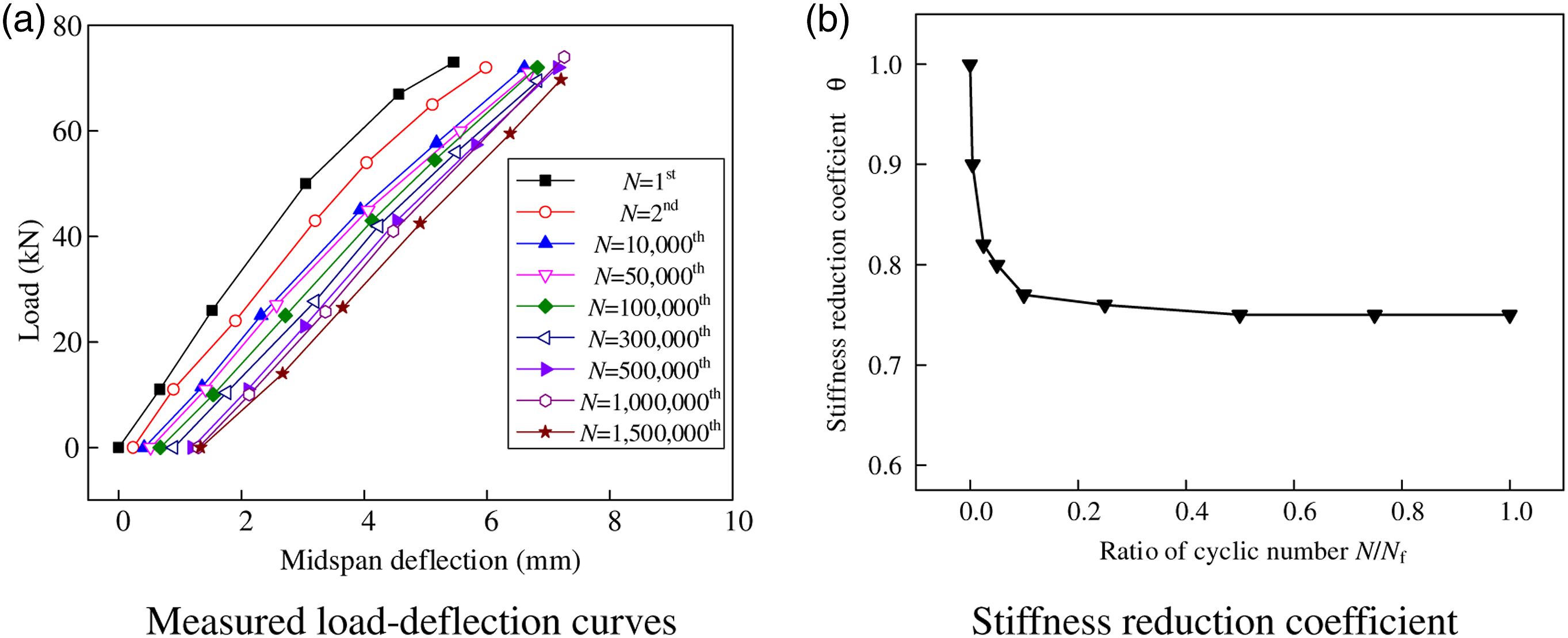
Test results of specimen BF-F. (a) Measured load-deflection curves and (b) stiffness reduction coefficient. Note: 1st, 2nd, 10,000th, 50,000th, 100,000th, 300,000th, 500,000th, 1,000,000th, and 1,500,000th are the numbers of cyclic loading.
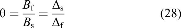
The measured stiffness reduction coefficients are shown in Figure 10(b). The stiffness reduction coefficient of specimen BF-F dropped to 0.77 in the first 15% of the fatigue life (N/Nf ≤ 0.15) and then remained basically constant for the rest of its fatigue life (N/Nf>0.15). The evolvement of stiffness of the beam was similar to that of the modulus of UHPC, as shown in Figure 1.
Model verification
The fatigue damage evolvement of specimen BF-F shows two stages: rapid development stage (N/Nf ≤ 0.15) and stable stage (N/Nf > 0.15). Although three stages are always expected in the fatigue experiment, the third stage of the tested specimen, which is the rapid development of fatigue damage after the stable stage, did not occur before 2 million cycles, since the maximum compressive stress in UHPC (σc = 55.7 MPa) is less than its fatigue strength (σF = 0.57fc = 65.6 MPa).
The fatigue evolvement of the strain, deflection, and crack width are obtained in the test. The maximum compressive strain in UHPC at midspan increases by 17% in the first stage and increases by only 3% in the second stage. The midspan deflection rapidly increases in the first stage. The second stage lasts for a long time, and the deflection remains basically unchanged. The maximum crack width increases by 0.03 mm and 0.01 mm in these two stages.
The test results were used to verify the FPM. The predicted cracking moment is 34.3 kN·m, which is consistent with the test results. The fatigue evolvement of the test and FPM results is compared in Figure 11. The predicted maximum compressive strain in UHPC is slightly higher than the test result but acceptable, as shown in Figure 11(a). There are deviations between FPM results and test results of the residual strain in UHPC, especially in the second stage of the fatigue evolvement, as shown in Figure 11(b). It should be noted that many factors can influence the evolvement of residual strain. The maximum deviation between FPM results and test results of the residual strain was about 90 με, which should be acceptable. However, the predicted midspan deflection and maximum crack width are consistent with the test results, as shown in Figure 11(c) and (d). The predicted macroscopic index of the beam has sufficient accuracy. In general, the developed FPM can be used to predict the fatigue behavior of UHPC beams prestressed with CFRP tendons. Comparison between test results and fatigue prediction model results. (a) Maximum compressive strain in UHPC, (b) residual strain in UHPC, (c) midspan deflection of the beam, and (d) maximum crack width in the beam. UHPC: ultra-high-performance concrete.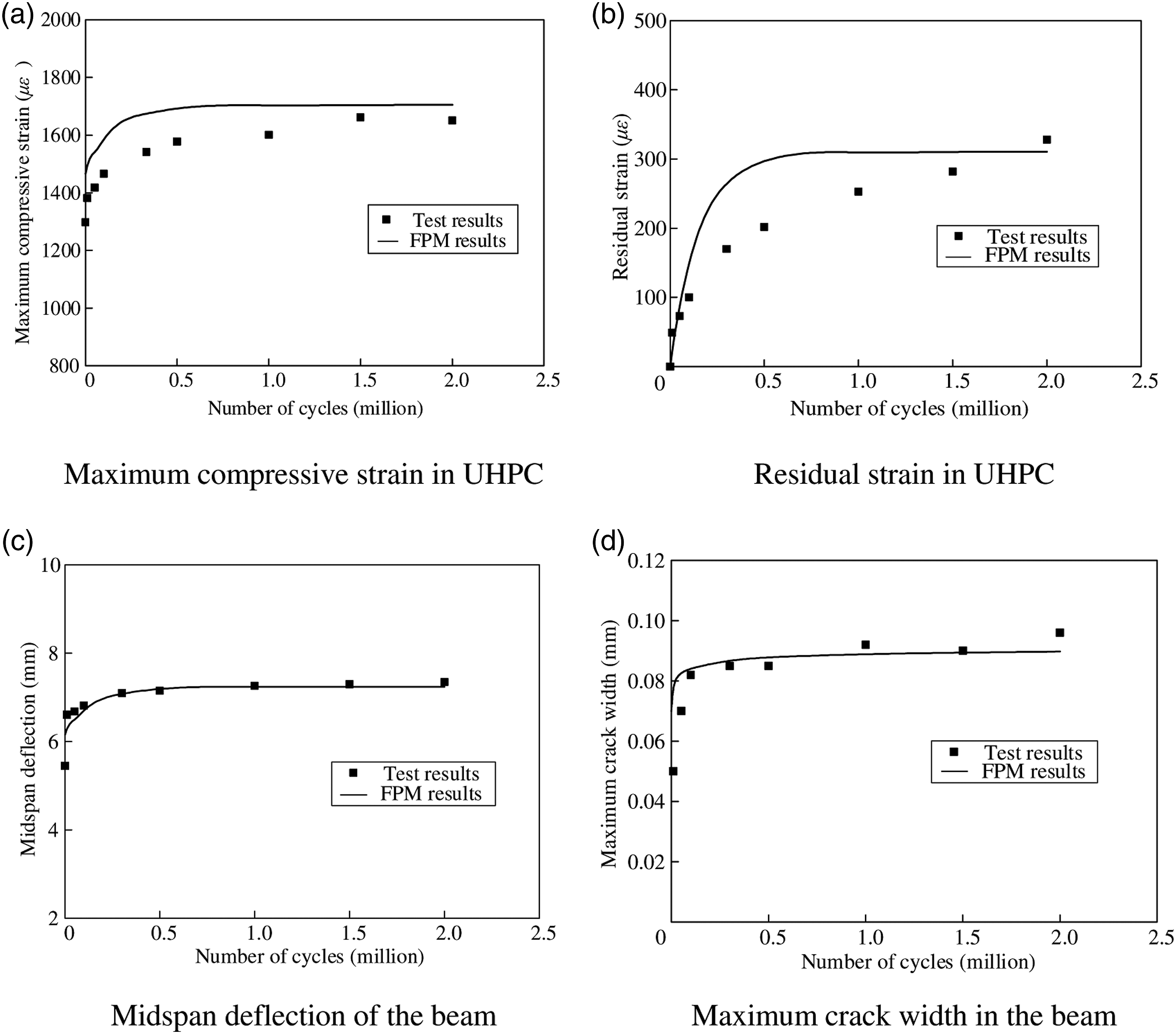
Parametric study
Fatigue damage evolvement
The fatigue damage of UHPC beams prestressed with CFRP tendons can be evaluated by the developed FPM. Note that the tested UHPC beams exhibited excellent fatigue behavior with fatigue life higher than 2 million times, and only two stages of fatigue development appeared in the experiment. In order to explore the whole three stages of fatigue development and the fatigue life of the UHPC beams, a parametric study of the fatigue damage evolvement of UHPC beams under different fatigue loads is performed. All geometric parameter and material properties of the specimens in parametric study are consistent with the test specimen. The upper limit of fatigue load is set to be 50%, 60%, 70%, and 80% of the static bearing capacity (Fmax), and the lower limit of fatigue load remains at 26% of the static bearing capacity. Note that shear tests of the beam were conducted in another experiment, and the maximum shear load of the tested beam was measured as 167 kN (Fang et al., 2020). The tested beams presented in this study were design to exhibit flexural failure. In the parametric study, the maximum load was less than the shear strength of the beams, and the calculated beams were considered as flexural failure. The fatigue evolvement of the strain, deflection, and crack width predicted by FPM are presented in Figure 12. Fatigue evolvement under different fatigue loads. (a) Maximum compressive strain in UHPC, (b) residual strain in UHPC, (c) midspan deflection of the beam, and (d) maximum crack width in the beam. UHPC: ultra-high-performance concrete.
It is known that the complete fatigue damage evolvement of the concrete structures passes through three stages under large load amplitudes. The fatigue damage usually quickly develops in the first and third stages but remains steady in the second stage. Figure 12 shows that the third stage of the fatigue damage evolvement does not occur in the UHPC beams under the maximum fatigue loads of 0.5Fmax and 0.6Fmax. The strain in UHPC, deflection, and maximum crack width of the beams remain steady at 2 million cycles. The three stages of fatigue damage evolvement occur in the UHPC beams under the maximum fatigue loads of 0.7Fmax and 0.8Fmax, although the third stage of fatigue damage evolvement of UHPC beam under the maximum fatigue load of 0.7Fmax is not obvious.
In Figure 12(a), the maximum compressive strain in UHPC steadily increases with the increase in maximum fatigue load, except for the beam under the maximum fatigue load of 0.8Fmax when the cyclic number exceeds 1.5 million.
The third stage of fatigue damage evolvement of the beam under the maximum fatigue load of 0.7Fmax is observed in the residual strain evolvement in UHPC, as shown in Figure 12(b). The residual strain in UHPC of the beam under the maximum fatigue load of 0.7Fmax is notably large at 2 million cycles but does not exceed 0.36ε0, which is determined as the fatigue failure criterion of UHPC.
The midspan deflection evolvement of the beams is almost identical under the maximum fatigue loads of 0.5Fmax, 0.6Fmax, and 0.7Fmax, as presented in Figure 12(c). The deflection increment between the beam under maximum fatigue loads of 0.6Fmax and 0.7Fmax is greater than that between the beam under maximum fatigue loads of 0.6Fmax and 0.5Fmax. The reason can be that the flexural stiffness of the beam reduces after the beam cracking, and the deflection rapidly increases. All three stages of fatigue damage evolvement can be observed in the deflection evolvement of the beam under the maximum fatigue load of 0.8Fmax.
The crack width evolvement between the beams under different maximum fatigue loads is plotted in Figure 12(d). The maximum crack width steadily increases with the increase in maximum fatigue load. The third stage of the fatigue damage evolvement of the beam under the maximum fatigue load of 0.8Fmax occurs but is not obvious. It can be noted that the steel fibers in UHPC can effectively constrain the crack development. The cracks on UHPC members were normally narrow and closely distributed, which led to subtle differences in the crack width evolvement.
To evaluate the fatigue damage of the component, fatigue damage index D is defined by the flexural stiffness, as expressed in equation (29)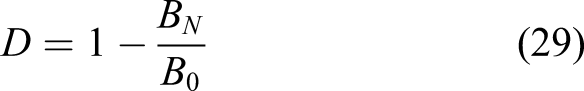
The fatigue damage index of the beam under different fatigue loads is presented in Figure 13. The fatigue damage index of the beam is basically unchanged when the maximum fatigue load is within 0.6Fmax. The fatigue damage index more rapidly increases when the maximum fatigue load exceeds 0.6Fmax, and all three stages of the fatigue damage evolvement clearly appear when the maximum fatigue load reaches 0.8Fmax. Compared with the beam with maximum fatigue load under 0.6Fmax, the fatigue damage index of the beam with maximum fatigue load 0.7Fmax of 0.8Fmax and at the load cycles of 2 million increases by 15% and 46%, respectively. Fatigue damage index under different fatigue loads.
Fatigue life prediction
If the fatigue load amplitude exceeds a certain value, the beams will fail under fatigue loading. For partially prestressed normal concrete beams, the fatigue failure is generally caused by the fracture of non-prestressed reinforcement (Elrefai et al., 2012; Mohamed, 2016). The fatigue failure of the prestressed normal concrete beams without non-prestressed reinforcement is mostly determined by the facture of prestressed tendons, except for the beams with excessive reinforcement ratios (Yin 2013). However, the fatigue property of CFRP tendons is notably different from that of steel bars, and UHPC has the advantage of favorable fatigue property (Yu et al., 2010). The flexural fatigue failure pattern of UHPC beams prestressed with CFRP tendons has not been discovered.
Unfortunately, fatigue failure did not occur to the UHPC beam in the present experimental study. Thus, the fatigue life of UHPC beams prestressed with CFRP tendons under different fatigue load amplitudes is analyzed using the developed FPM. The predicted residual strain in UHPC at the top surface of the cross section and stress amplitude in CFRP tendons at midspan are presented in Figure 14. Fatigue behavior of the materials in UHPC beams. (a) Residual strain in UHPC at 2 million cycles and (b) stress amplitude in carbon-fiber-reinforced polymer tendons at 2 million cycles. UHPC: ultra-high-performance concrete.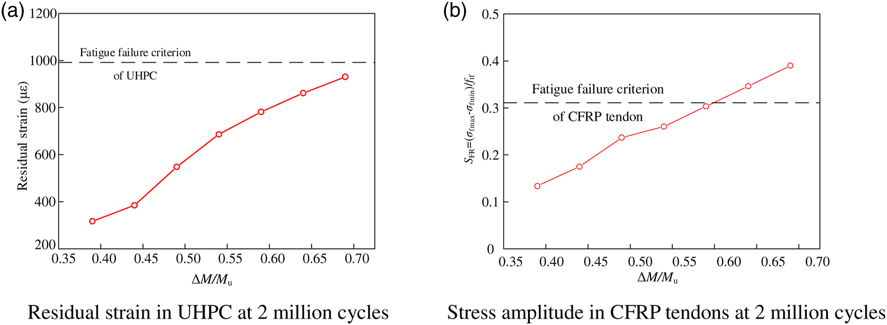
The fatigue failure criteria of the materials are also presented in Figure 14. The fatigue failure of CFPR tendons occurs earlier than UHPC, and the fatigue failure of the UHPC beam prestressed with CFRP tendons depends on the fatigue life of the CFRP tendons.
The fatigue life (Nf) of UHPC beams prestressed with CFRP tendons under different fatigue load amplitudes is presented in Figure 15. Based on the regression analysis, the relationship between the fatigue life and load amplitude can be described in equation (30). It can be found that the fatigue load amplitude of such beam should not exceed 62% of its static bearing capacity if the fatigue life must exceed 2 million cycles Prediction of the fatigue life.

Conclusions
Based on the fatigue constitutive model of UHPC and CFRP tendons, a fatigue prediction model (FPM) for UHPC beams prestressed with CFRP tendons was established. The developed FPM was used to evaluate the fatigue evolvement of UHPC beams prestressed with CFRP tendons under different fatigue loads. The following conclusions can be drawn from this study: 1. The UHPC beam prestressed with CFRP tendons exhibited good fatigue properties. The tested beam under the maximum fatigue load of 0.65Mu and the minimum fatigue load of 0.26Mu did not fail after 2 million cycles. The fatigue damage rapidly increased in the first stage (N/Nf ≤ 0.15) and remained stable for the remainder of the fatigue life (N/Nf > 0.15). The third stage of the fatigue evolvement did not occur in the tested specimen. 2. The strain and stress in the UHPC and CFRP tendons, deflection of the beam, and maximum crack width in the beam can be predicted in the FPM. The compressive and residual strain in UHPC predicted by the FPM were acceptable compared to the test results. However, the predicted midspan deflection of the beam and maximum crack width in the beam were consistent with the test results. In general, the developed FPM can be used to predict the fatigue behavior of UHPC beams prestressed with CFRP tendons. 3. The parametric study shows that the fatigue life of the UHPC beams prestressed with CFRP tendons depends on the fatigue failure of the CFRP tendons. The relationships between the fatigue life and the load amplitude were obtained, and the formula to predict the fatigue life of UHPC beams prestressed with CFRP tendons was proposed. The fatigue load amplitude of UHPC beam in the present experimental study should not exceed 62% of its static bearing capacity if the fatigue life must exceed 2 million cycles. The analysis process can be used to predict the fatigue life of all kinds of UHPC beams prestressed with CFRP tendons.
Footnotes
Declaration of conflicting interests
The author(s) declared no potential conflicts of interest with respect to the research, authorship, and/or publication of this article.
Funding
The author(s) disclosed receipt of the following financial support for the research, authorship, and/or publication of this article: This research was supported by the National Natural Science Foundation of China (grant number: 51938012), and the Ministry of Science and Technology (grant number: 2017YFC0703008).