
Abstract
The attenuation zones (AZs) of periodic structures can be used for seismic isolation design. To cover the dominant frequencies of more seismic waves, this paper proposes a new type of periodic isolation foundation (PIF) with an extremely wide low-frequency AZ of 3.31 Hz–17.01 Hz composed of optimized unit A with a wide AZ and optimized unit B with a low-frequency AZ. The two kinds of optimized units are obtained by topology optimization on the smallest periodic unit with the coupled finite element-genetic algorithm (GA) methodology. The transmission spectra of shear waves and P-waves through the proposed PIF of finite size are calculated, and the results show that the AZ of the PIF is approximately the superposition of the AZs of the two kinds of optimized units. Additionally, shake tests on a scale PIF specimen are performed to verify the attenuation performance for elastic waves within the designed AZs. Furthermore, numerical simulations show that the acceleration responses of the bridge structure with the proposed PIF are attenuated significantly compared to those with a concrete foundation under the action of different seismic waves. Therefore, the newly proposed PIF is a promising option for the reduction of seismic effects in engineering structures.
Introduction
In the last several decades, reducing the possible damage caused by strong ground motion in engineering structures has been a popular topic (De Domenico et al., 2019; Xu et al., 1999). Among the existing methods, base isolation is acknowledged as an effective method for protecting mid-rise and low-rise building structures under firm and medium soil conditions and has been adopted by many seismic design codes. In recent years, to further improve the seismic reduction performance of base isolation systems, some new low-cost elastic isolators or dampers and novel mechanical systems such as negative stiffness devices or inerter-based systems have been developed (Li et al., 2018; Losanno et al., 2019; Zhao et al., 2019). Even today, research on novel seismic isolation strategies is still an active field (Castaldo and Ripani, 2016; Tsang and Pitilakis, 2019).
Within this context, a novel isolation system inspired by the filtering effect of periodic structures has been proposed (Aravantinos-Zafiris et al., 2021; Chen et al., 2021; Golub et al., 2021). One of the characteristics of periodic structures is the existence of frequency attenuation zones (AZs), that is, frequency regions where waves and vibrations are inhibited or attenuated along their propagation path. Based on this property, a novel seismic reduction method called the periodic isolation foundation (PIF) has been proposed in recent years (Cheng et al., 2020; Jia and Shi, 2010), and a comparison between the PIF and the traditional isolation foundation is presented in Figure 1(a). (a) The superstructures with traditional isolation foundation and PIF; (b) three types of PIF; (c) the smallest periodic unit to be optimized with three-phase materials, where the blue, yellow and red components represent the corresponding grids are filled with concrete, rubber and steel, respectively; (d) the illustration of 2D PIF.
According to the spatial periodicity, PIFs can be divided into three types: one-dimensional PIFs (1D PIFs), two-dimensional PIFs (2D PIFs), and three-dimensional PIFs (3D PIFs), as shown in Figure 1(b). 1D PIFs were studied by Shi et al. (2014), Witarto et al. (2019), Xiang et al. (2012) and Jain et al. (2019), and they found that a 1D PIF can generate wide AZs. However, the displacement responses of 1D PIFs increase under the action of earthquakes due to the lack of horizontal stiffness, resulting in hidden problems in practical applications. In regard to 3D PIFs, the studies by Basone et al. (2019), Shi and Huang (2013) and Ma et al. (2019) conclude that 3D PIFs can isolate seismic waves incident from three directions, but they are difficult to construct in practice.
Studies on 2D PIFs date back to 2010 when a 2D three-component PIF was developed to protect a superstructure (Jia and Shi, 2010), and the obtained AZ, which was narrow in width, ranged from 2.49 Hz to 3.72 Hz. Then, the AZs of a two-component periodic structure composed of concrete and rubber and a three-component periodic structure composed of concrete, rubber and steel were investigated by Cheng and Shi (2013), with ranges of 7.22 Hz–10.11 Hz and 4.17 Hz–8.17 Hz, respectively. Although these ranges of AZs were expanded to some extent, the frequencies of these AZs were high. Furthermore, a type of PIF with rotational oscillators with extremely low-frequency AZs was proposed by Huang et al. (2017), but the obtained AZs were narrow. More recently, Casablanca et al. (2018) proposed a seismic isolation system based on a device that combines some properties of periodic mass-in-mass systems with those of a standard foundation positioned right below the building, and the obtained AZ started at 4.5 Hz.
The AZs of these proposed 2D PIFs are high in frequency or limited in width, but the possible types of ground motions are random in practice. On the other hand, seismic waves whose dominant frequencies are lower than 5 Hz are difficult to attenuate. Therefore, it is necessary to develop new PIFs with both broad- and low-frequency AZs to overcome these issues. The first contribution of this work is the proposal of a new kind of PIF composed of two kinds of topology-optimized units with wide- and low-frequency AZs. The vibration reduction performance of the proposed PIF in finite size is also studied. The optimization process is performed with a coupled finite element-genetic algorithm (GA) methodology. In addition, although PIFs have been proposed to isolate seismic waves, there has been little experimental validation. This paper carries out shake tests on the ability of a scale PIF specimen to attenuate elastic waves within the designed AZ. These demonstrate that the proposed PIF can be manufactured and that the obtained AZs in a real PIF can be used for seismic isolation. Finally, the attenuation performance of the proposed PIF and a concrete foundation (CF) under seismic accelerations for different soil conditions are compared by numerical analysis.
Methods
The PIF is composed of numerous smallest periodic units extending in the planar x and y directions, as shown in Figure 1(d), and one smallest periodic unit can represent the entire PIF according to Bloch–Floquet theory (Golub et al., 2021). On the other hand, PIFs are made of concrete, rubber and steel, which are commonly used materials in civil engineering, and the topology optimization of these three components has a larger search space than that of any two of the components in the search for a more suitable PIF. Therefore, to obtain the PIF with an ideal AZ, the smallest periodic unit is chosen as the optimization object, and topology optimization with three-phase materials is carried out. Each edge of the unit is equally divided into
Calculation of dispersion curves with finite element method (FEM)
For two-dimensional periodic structures, all components are assumed to be continuous, isotropic, perfectly bonded and without material damping. Therefore, the wave equation can be written as

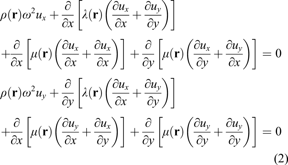
According to Bloch’s theorem, the displacement vector can be expressed as


Combined with Equations (1)–(5), the dispersion relation of the periodic system can be transformed into an eigenvalue equation

The improved three-phase material GA
A GA can continuously search for optimal results through scientific methods. The optimization process of the GA starts from an initial population containing some chromosomes. Then, qualified individuals are selected from the parents for the new generation according to the calculated fitness values. Crossover and mutation operations are applied to produce new individuals. The probabilities of crossover and mutation are
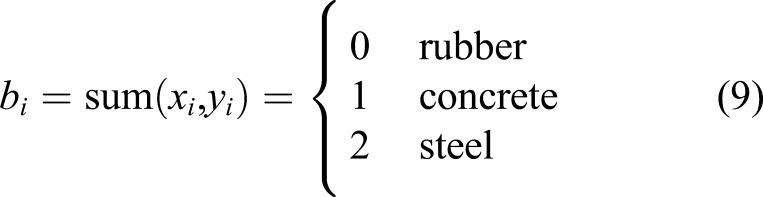
Previous work demonstrated the efficiency of the GA in designing 2D phononic crystals (Dong et al., 2014a; 2014b), where grids can be filled with either of two selected materials corresponding to the binary digits, that is, 0 or 1, in the chromosome. Although this is effective for the optimization of units with two-phase materials, it is not ideal for structures with multiphase materials. To address the topology optimization of a PIF unit composed of concrete, rubber and steel (CRS unit), the binary pair (Xu et al., 2020) is simply adopted in this study
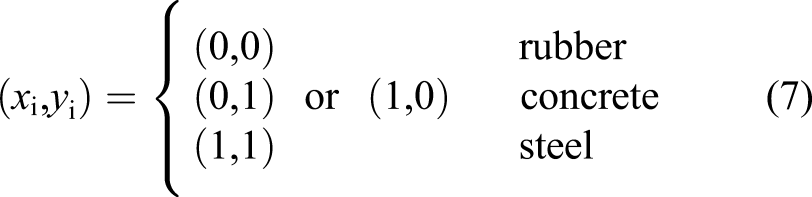
In this way, a chromosome with a length of 2l can be expressed as l individuals Illustration of the coding and decoding of the CRS unit: (a) coding in the chromosomes; (b) The corresponding relationship between digits in the chromosome and pixels of the unit, in which the red dotted line box is 1/8 of the unit structure. (c) Decoding, and the coding digits 0, 1 and 2 represent that the corresponding pixels are filled with rubber, concrete and steel, respectively.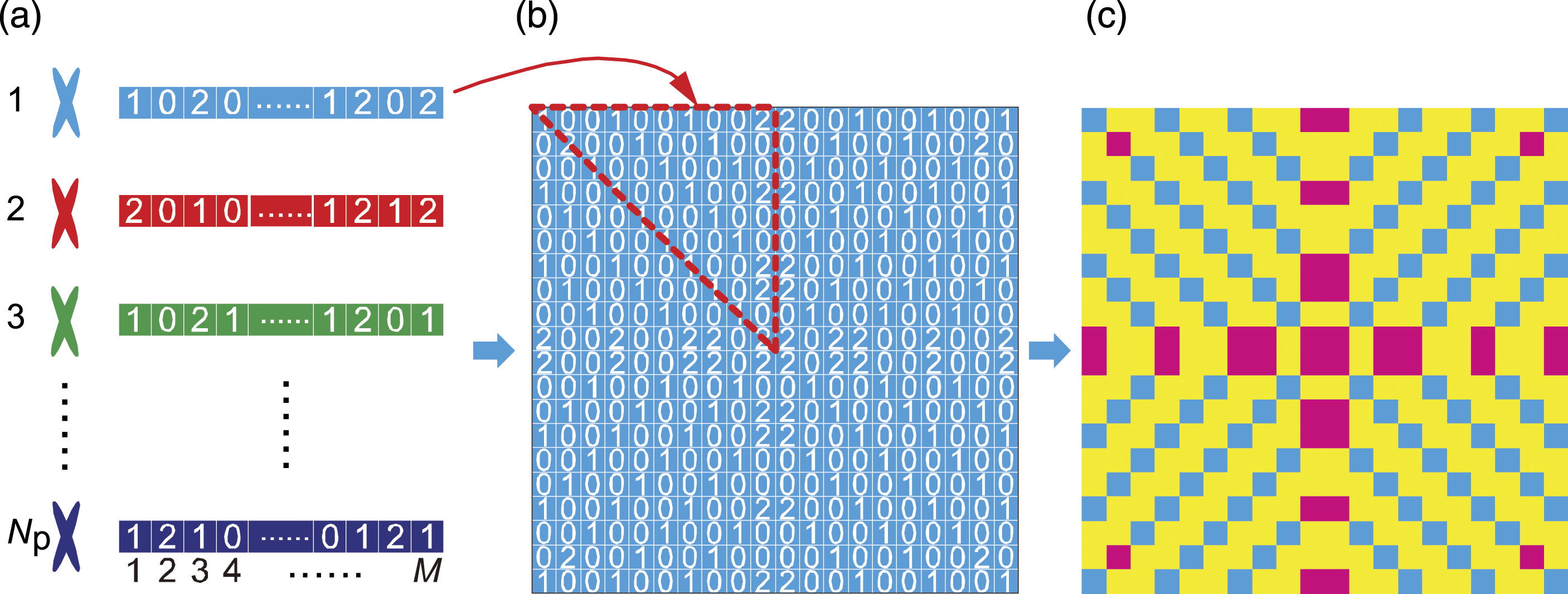

Considering the need for a good interaction between the dispersion curve calculation and GA program, the topology optimization program is operated in the software COMSOL Multiphysics 5.4a with MATLAB, where the GA program is written in MATLAB and COMSOL Multiphysics 5.4a is used to calculate the dispersion curves. The overall topology optimization process is shown in Figure 3. Optimization process of the PIF unit.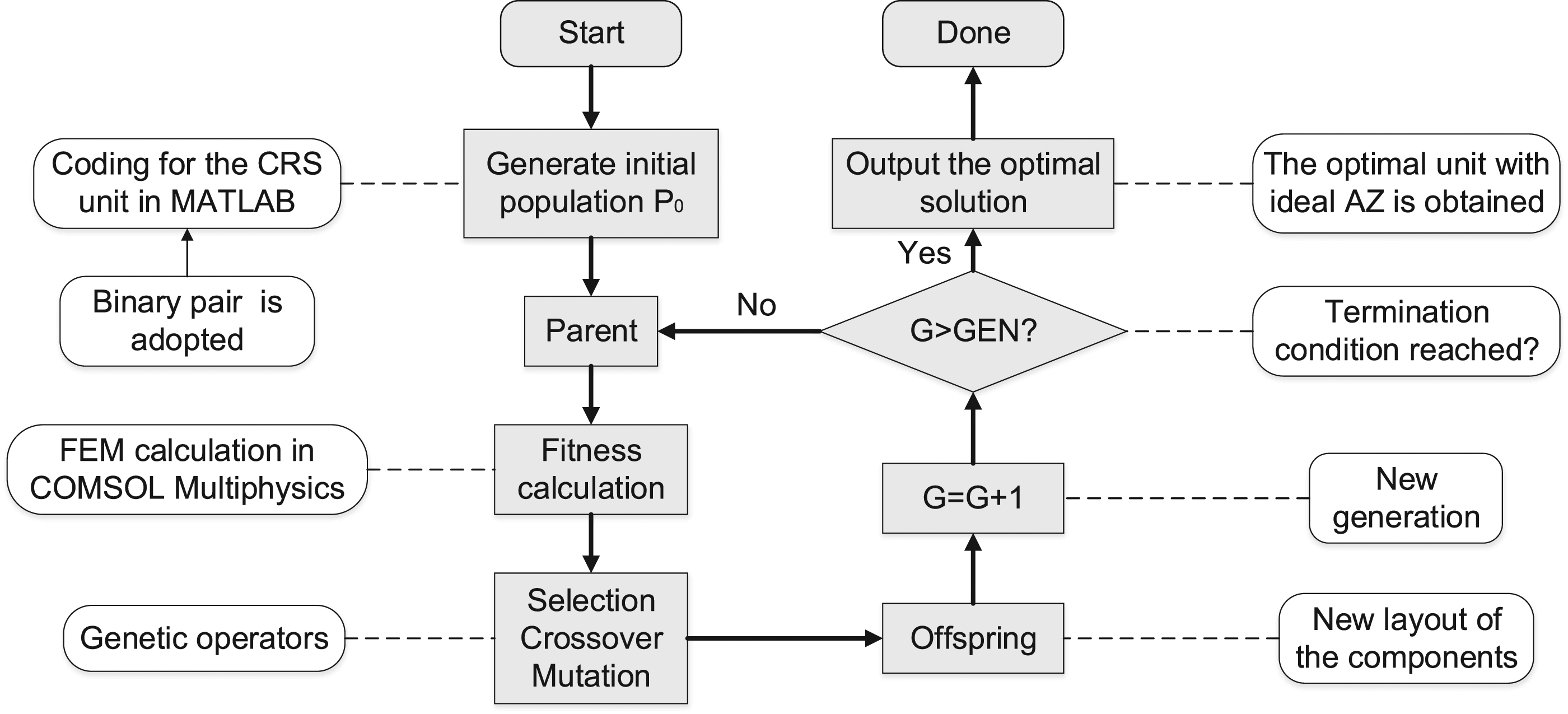
Topology optimization on the units
Unit A with broad AZ
Material properties.

To limit the deformation of the rubber blocks and to maintain the stability of the overall shape of the PIF, the outermost grids of the unit are filled with concrete, while topology optimization is conducted only in the inner grids. In this way, live and dead elements are used in the optimization program. As shown in Figure 4, the outermost grids of the unit that does not participate in the assignment of the materials during the evolution are dead elements and are fixed with coding digit 1, while the internal grids are set as live elements, and the gene digits corresponding to the three materials are randomly generated for the later optimization operations. Live and died elements, encoding and decoding.
The first two in-plane bands are rigid at point (a) The evolution progress; (b) the dispersion curve of the optimized unit A, the inset is the first Brillouin zone; (c) The topology structures corresponding to the 50th generation, 100th generation, 150th generation, 200th generation and the optimized unit A, where the blue, yellow and red parts represent that the corresponding grids are filled with concrete, rubber and steel, respectively.
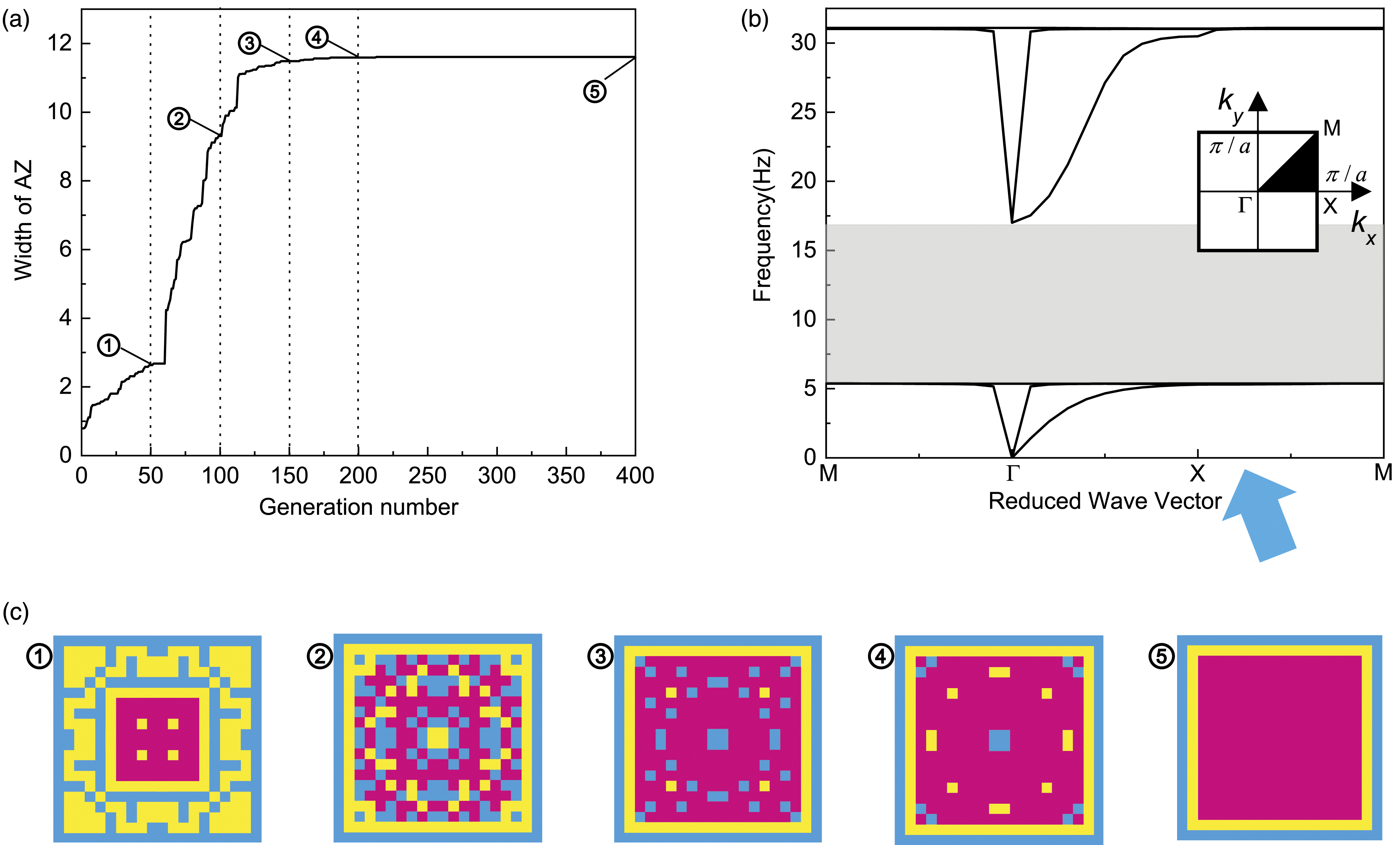
Figure 5(a) shows that the width of the AZ converges to 11.61 Hz after the 213rd generation. In optimized unit A (shown in Figure 5(c)), which has an AZ of 5.4 Hz–17.01 Hz, a thin rubber layer is placed between the outer concrete layer and the central steel block.
Unit B with constrained low-frequency AZ
The dominant frequencies of many seismic waves are lower than 5 Hz, and the AZ of obtained unit A starts from 5.4 Hz, so we hope to further lower the frequency of the AZ. In addition, a certain width of AZ is necessary to ensure the seismic attenuation effect. Hence, the constrained GA is used to minimize the starting frequency ( (a) The evolution process, the inset is a sketch of the optimized unit B, where the blue, yellow and red parts represent that the corresponding grids are filled with concrete, rubber and steel, respectively. (b) the corresponding dispersion curve of unit B.
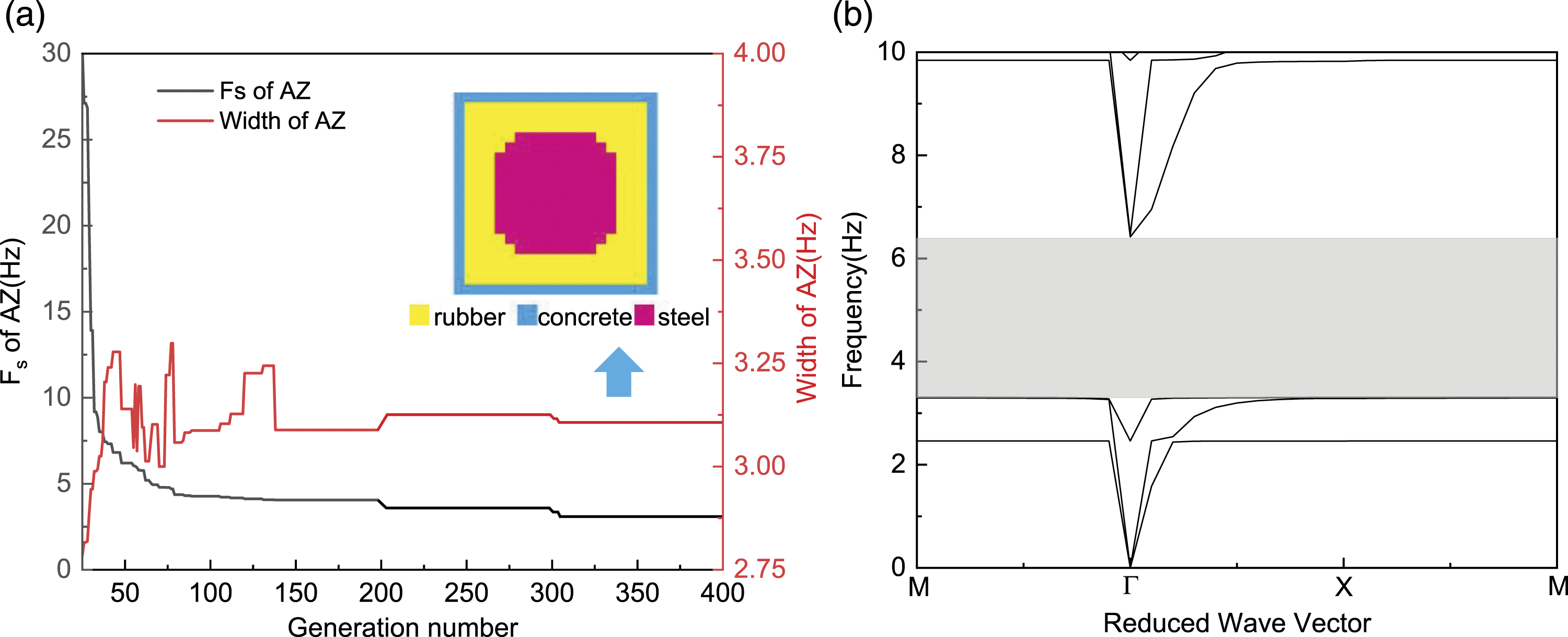
It is shown that the 
The PIFs with different combination modes
Based on the above optimization calculation and analysis, novel PIFs with theoretical in-plane AZs from 3.31 Hz to 17.01 Hz can be obtained by the combination of optimized unit A and unit B. Considering the interaction between different PIF units, the isolation performance of the following four PIFs as shown in Figure 7 with different combination modes are studied. The period numbers of unit A and unit B along a certain incident direction of seismic wave are Four kinds of periodic isolation foundation with different combination modes.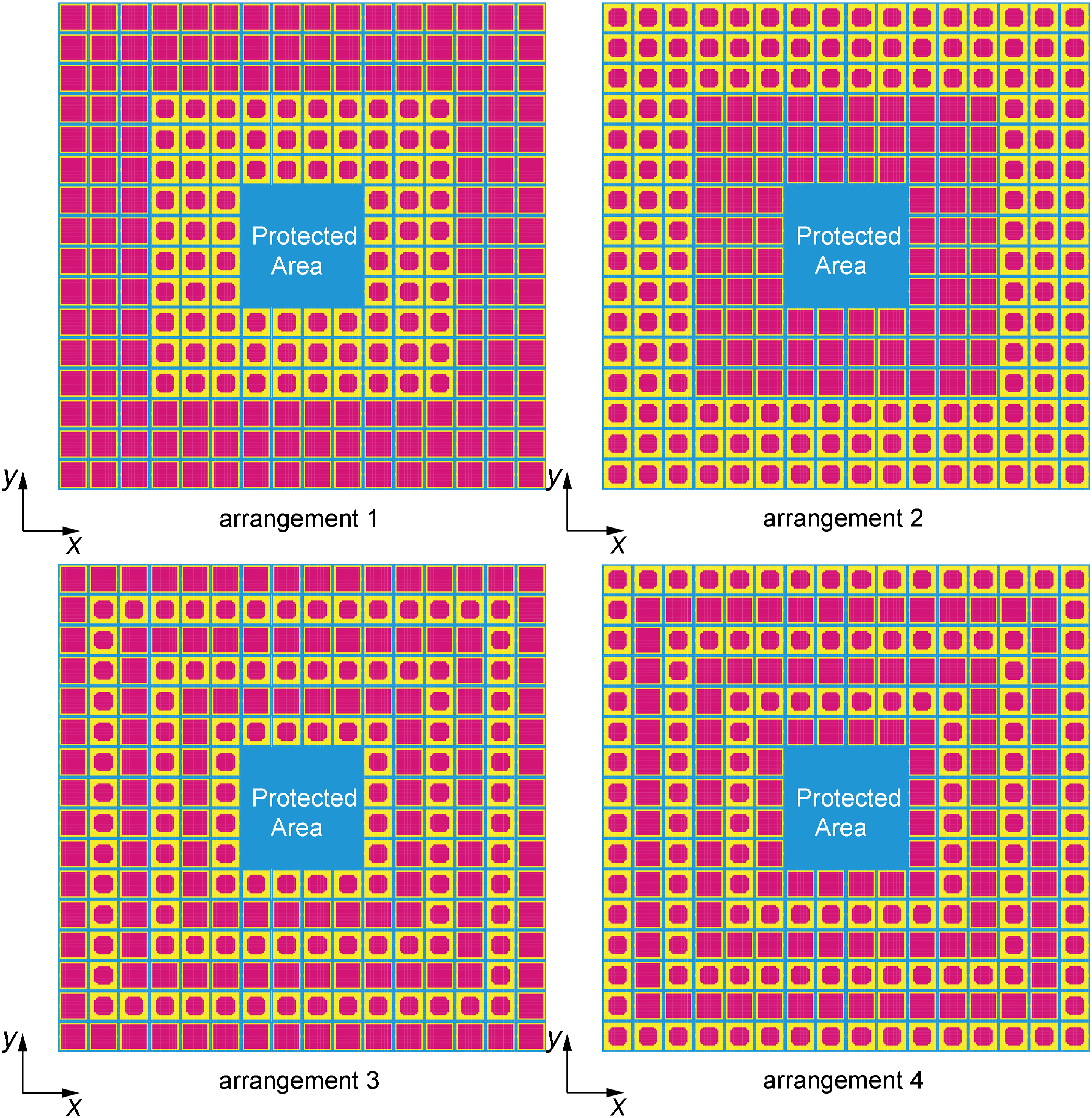
Vibration reduction performance of the PIF in finite size
The selected PIF mode
Note that in practice, the size of the foundation is limited, not infinite; Here, we take
A harmonic displacement excitation varying in frequency in the x or y direction is applied to each node on the left side of the four finite PIFs, while the degree of freedom in the other direction is constrained, and the corresponding response in the same direction as the excitation in the protected area is received to simulate an incident P-wave and shear wave. The frequency response function (FRF) is calculated by equation (13) (Cheng and Shi, 2013)
As shown in Figure 8, the obtained AZs are all similar to the theoretical AZ (shaded in grey area) for the four combination modes, but the positions and heights of the interference formants caused by the interactions between units are slightly different. Specifically, for P-wave, there is little difference in the AZs for the four arrangement modes. For shear waves, the obtained AZ with arrangement 1 is wider than those of the others, the interaction between the units has the least impact on the AZ under this circumstance. Note that similar results can also be found for the other periods number N. Therefore, the PIF with arrangement 1 is selected as the proposed PIF and its isolation performance will be mainly discussed in the following sections. (a) Shear wave transmission spectra and (b) P-wave transmission spectra with different arrangement modes.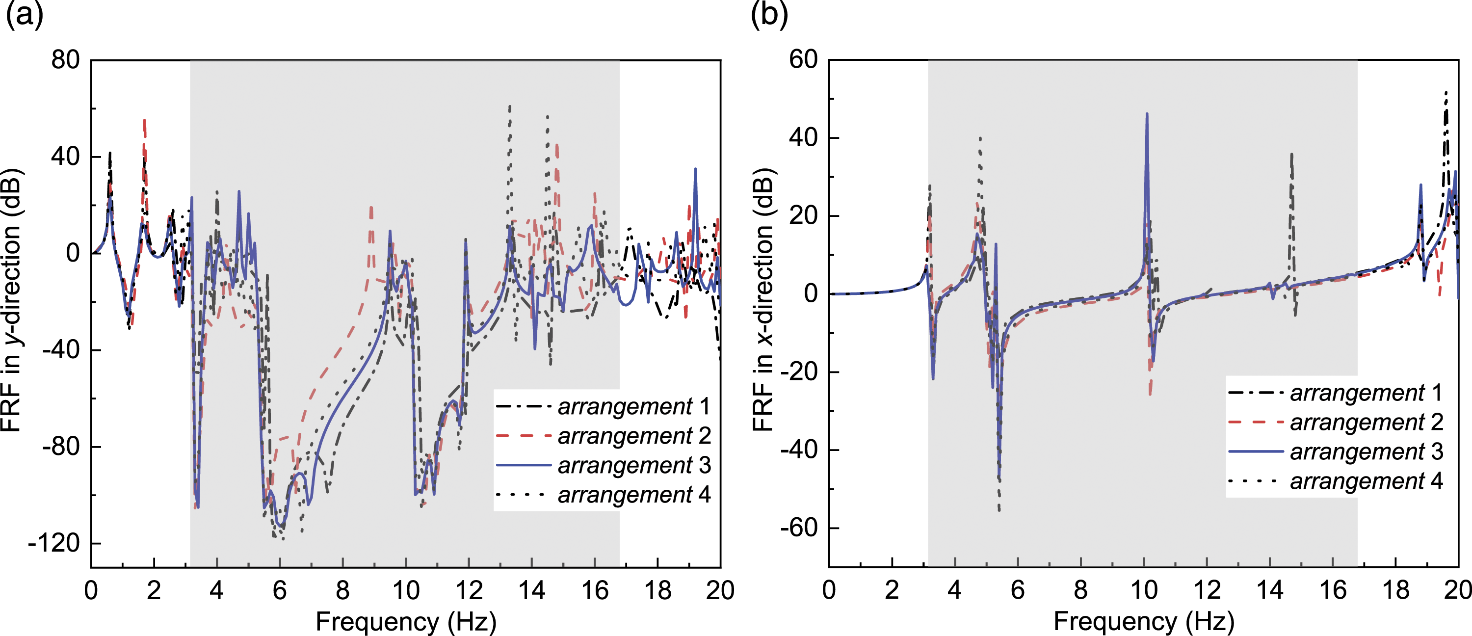
The influence of the period number
To further determine the influence of the limited size on the elastic wave attenuation performance. Assume that
Figure 9(a) shows the FRF curve of shear waves from 0 Hz to 20 Hz with a step of 0.01 Hz for the proposed finite PIF. For comparison, the theoretical AZ of the infinite PIF, which is the superposition of the AZs of the optimized unit A and unit B, is also plotted in the grey shaded area. The attenuation range of the finite PIF is nearly consistent with the theoretical AZ of the infinite structure, although there are some formants that interfere with the AZ. In contrast, there is no obvious attenuation for the FRF curve with n = 0, which is in sharp contrast with the effect of the PIF. In addition, the displacement response decays sharply in a small range near the (a) The FRF curves of shear waves, where the grey shaded area is the theoretical AZ of the infinite structure; (b) the displacements in y direction of the points at different positions of the median line with the excitation frequencies of 2 Hz and 6 Hz, where the blue shaded area is the position of protected area.
Figure 9(b) shows the displacements in the y direction at different positions of the median line (
Figure 10(a) shows the P-wave FRF curves of the finite PIF from 0 Hz to 20 Hz. Similar to the results of shear waves, the AZ of the finite PIF calculated from the transmission curve is basically consistent with that of the infinite structure obtained from the dispersion curves of the two kinds of subunits, although some formants are found in the AZ. The Fano profiles can also be observed in the FRF curves. Figure 10(b) and (c) plot the displacement modes with the excitation frequencies within and outside the AZ, respectively. For an elastic wave whose frequency is outside the AZ ( (a) FRF curves of P-wave, where the grey shaded area is the theoretical AZ of the infinite structure; (b) Displacement mode diagram with the excitation frequency f = 6 Hz and (c) displacement mode diagram with the excitation frequency f = 1.5 Hz.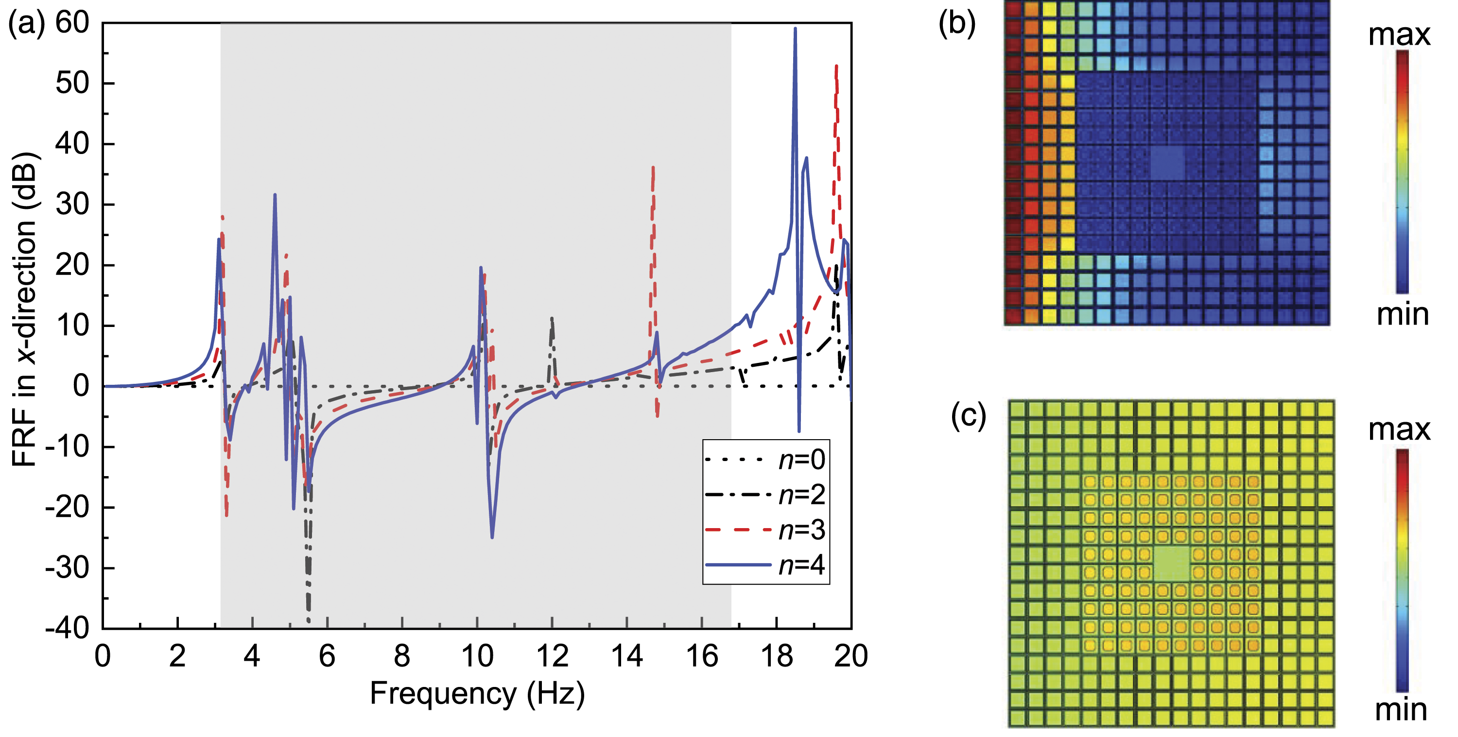
Experiment and results
Although the effectiveness of the AZ in the proposed PIF has been theoretically verified, it is necessary to carry out experiments to investigate its actual vibration isolation performance. One challenge is the manufacture of thin-walled hard components as the outer peripheral matrix, and another is the realization of the perfect bonding of the three components in the whole structure. To implement this design and to verify the effectiveness of the obtained AZs, shake tests on a scale PIF specimen are presented in detail.
Test setup and procedures
As shown in Figure 11(a), the scale PIF specimen is composed of steel cores and rubber connectors. Polymethyl methacrylate (PMMA), which is widely used in manufacturing structural models due to its high strength and simple fabrication (Huang et al., 2017), is used to fabricate the matrix instead of concrete in this paper. The material properties are tested in the laboratory, and the results are shown in Table 2. To form the target shape with ideal precision, the steel cores are cut out by laser from standard 304 stainless steel plates, and the rubber linkers are cast in moulds. The steel cores, rubber connectors and the PMMA matrix are bonded together by superglue with a tight fit to avoid debonding during the shake tests. The thicknesses of the rubber connectors, steel cores and PMMA matrix are all 0.01 m, and the period constant is 0.1 m. The scale specimen is composed of 4 × 3 optimized units A and 4 × 3 optimized units B, which can simulate the attenuation of elastic waves after they pass through the two kinds of periodic units. (a) the test specimen and (b) Test setup. Material properties used in the test.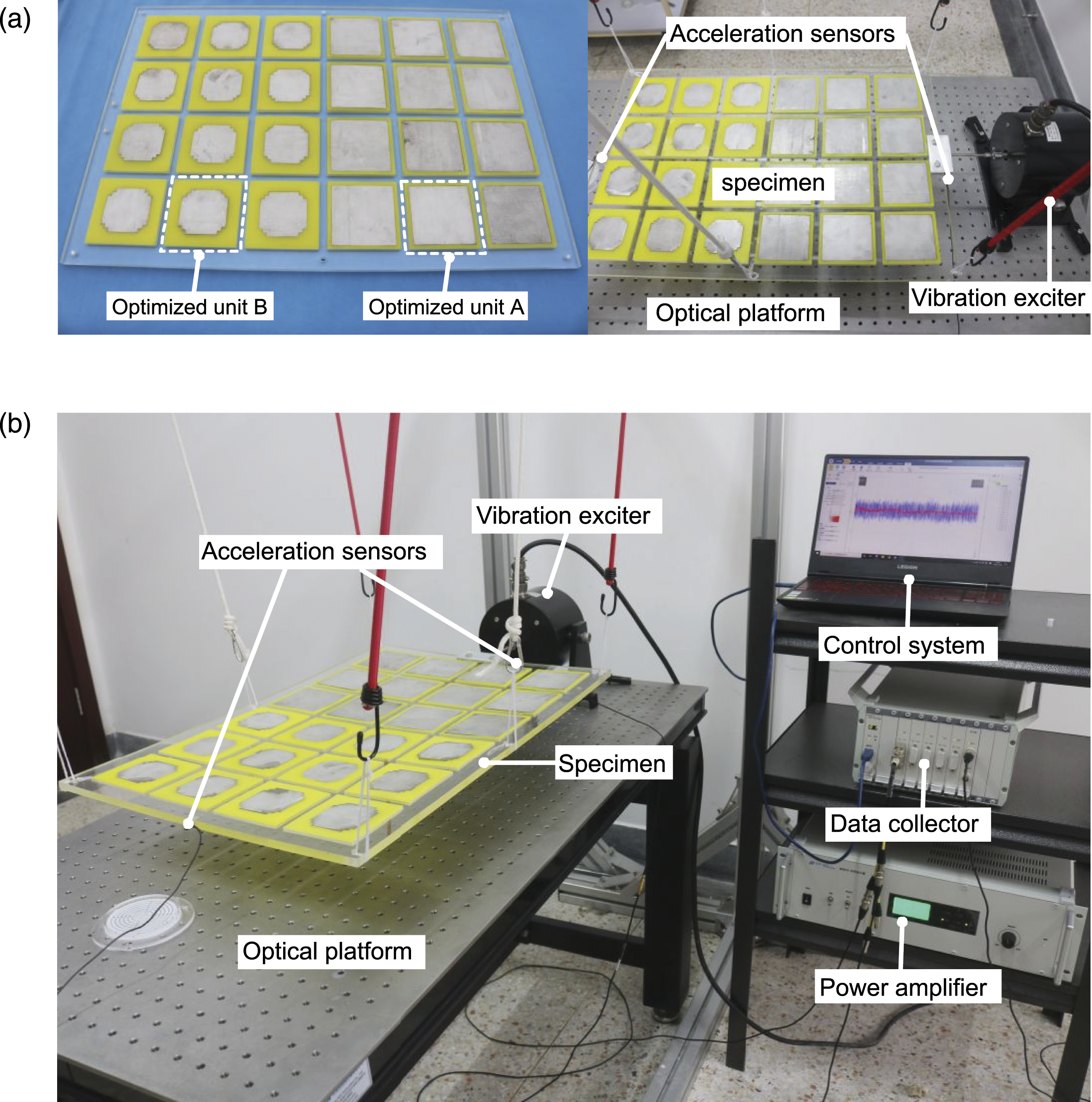

Figure 11 shows the fabricated specimen and the setup of the experimental instruments. The test system is composed of an optical platform, a vibration exciter, a power amplifier, a data collector, a control system and two acceleration sensors. The test specimen is suspended by six ropes to simulate the plane motion of the PIF under the action of a horizontal seismic wave. Although the friction force between the PIF and the ground is neglected, the test can still accurately reflect the AZ feature of the PIF. Then, the exciter is fixed on the optical platform to avoid vibration interference from the surrounding environment and is connected with the specimen through a mould. One accelerometer, used to detect the output acceleration by the data collector, is attached to the middle point of the front side on the test specimen, and the other accelerometer is attached to the excited side of the specimen. During the shake tests, the excitation signals are generated from the control system and act on the vibration exciter through the power amplifier.
Test results
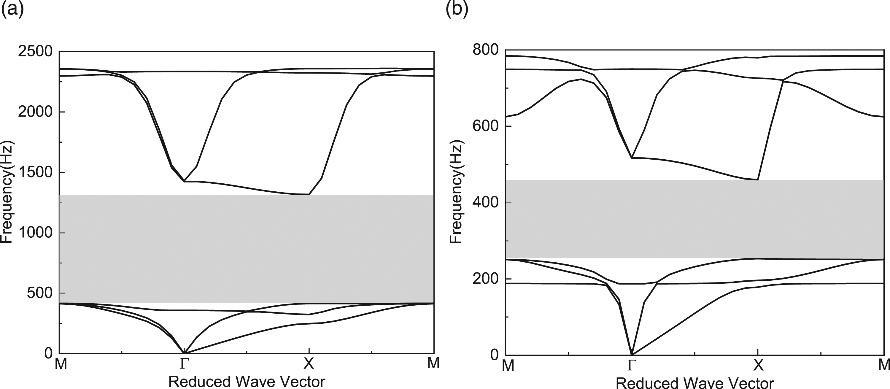
First, a sweep frequency shake test with an excitation frequency of 0 Hz–2000 Hz is performed. The FRF curve is obtained by processing the signal data of the input and output accelerometers through equation (13), and the obtained experimental results and the numerical calculation results of the scale specimen are plotted in red solid line and black dotted line in Figure 12, respectively. In addition, the corresponding dispersion curves of the two kinds of scale units are shown in Figures 13(a) and (b). The AZ obtained from the test results, the AZ calculated from the transmission spectrum by the FEM and the superposition result of the AZs of the two kinds of scale units are approximately the same, ranging from 253 Hz to 1360 Hz. This proves that the results of the numerical calculation are reliable and that the AZ of the proposed PIF is approximately the superposition of the AZs of the two kinds of scale units. The small mismatch between the theoretical and experimental results can be explained by the fact that the actual thickness of the PMMA plate is limited. In addition, there are two minima at 253 Hz and 420 Hz that correspond to the starting frequencies of the AZs of scale unit A and scale unit B, respectively. This can be explained by the Fano profiles of the two kinds of scale units, in which there are strong attenuations at the The experimental and calculated FRF curves, where HF represents the homogeneous PMMA foundation. Theoretical dispersion curves of (a) scale unit A and (b) scale unit B.
Second, constant frequency shake tests for elastic waves within and outside the AZs are carried out. Figure 14(a) shows that the output response on the specimen is greatly reduced when the excitation frequency falls into the AZs (600 Hz). In contrast, Figure 14(b) shows that the specimen has no effect on the attenuation of the elastic wave when the excitation frequency is outside the AZs (200 Hz) and that the output response may even be amplified, which is consistent with the prediction of the numerical simulation. Harmonic response with the excitation frequency of (a) 600 Hz and (b) 200 Hz.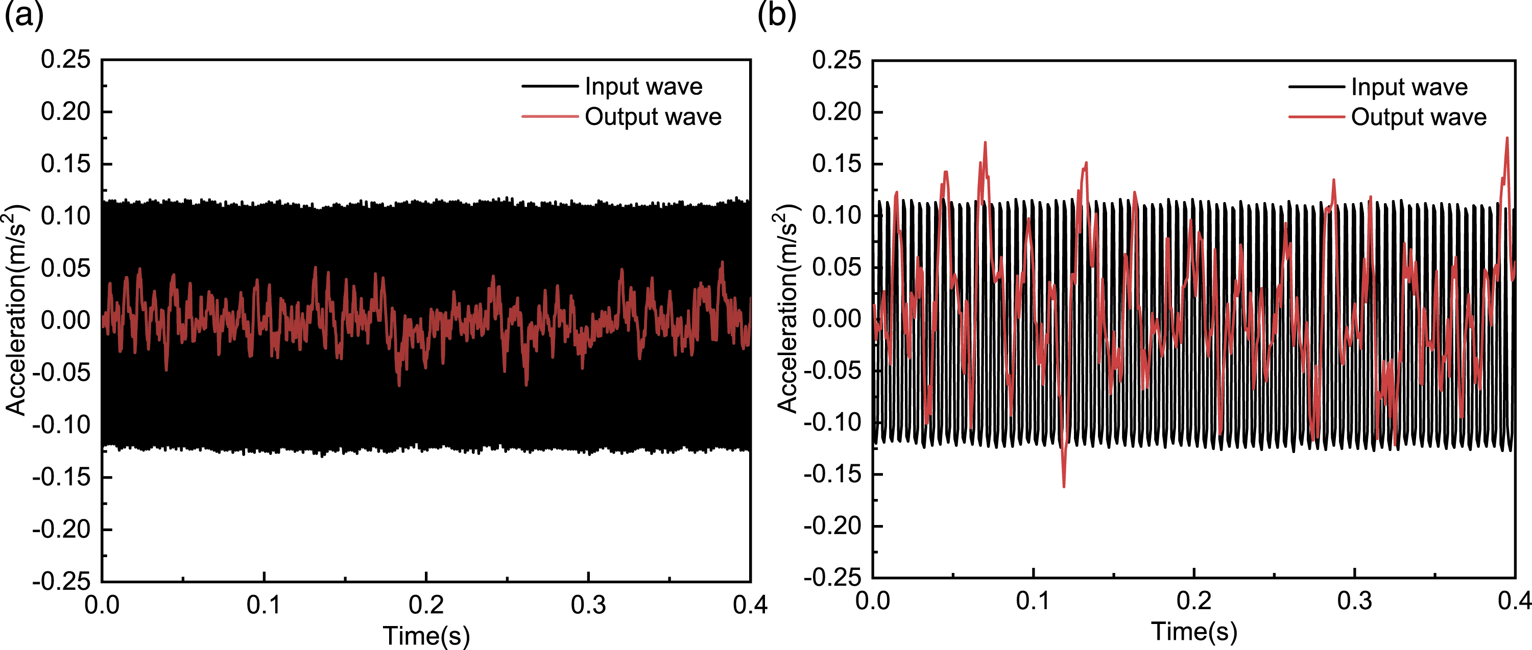
Seismic isolation application
In this section, the proposed PIF is used for seismic isolation in a bridge structure, and the dynamic responses of the upper bridge structure are studied by ABAQUS software. For comparison, a bridge structure with a same-sized CF is also modelled. Ideally, the proposed PIF can isolate most of the seismic waves and cover the fundamental frequencies of the upper bridge structure to avoid resonance.
A continuous rigid frame bridge structure with a variable cross-section box girder is modelled. For the proposed PIF, the geometric and material parameters are the same as those in topology optimization on the units, and the thickness is 2 m. The numbers of the two kinds of optimized units from the incident wave to the bottom of the piers are both 2; that is,
In regard to the boundary conditions in the numerical models, the bottoms of the two kinds of foundations are vertically constrained, and free boundary conditions are applied to the sides of the foundations, consistent with those in the experimental model. A vertical restraint is also applied to the two ends of the box girder. In addition, seismic acceleration excitation is applied to all nodes on the left sides of the foundations. The vibration direction of the seismic waves is transverse to the girder (along the x direction), and the corresponding acceleration responses in the x direction are extracted at three representative locations of the bridge deck (observed points A, B and C). In this way, the responses of the bridge systems subjected to shear waves can be modelled. The geometric parameters, meshes and boundary conditions for the two kinds of bridge systems are shown in Figure 15. The geometric parameters, meshes and the boundary conditions for (a) the bridge structure with the proposed PIF and (b) the bridge structure with concrete foundation.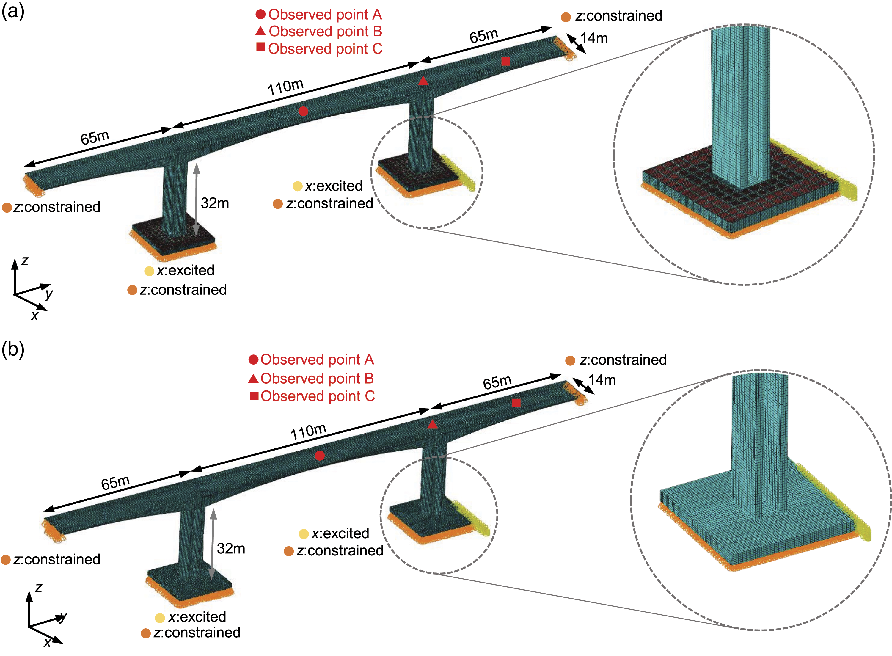
Responses to harmonic incident waves
First, the responses of the bridge structure with the proposed PIF under the incident of harmonic waves are considered. The governing equation of harmonic responses under small amplitude excitation is as follows (Huang et al., 2017)

Combined with equations (14) and (15), the amplitude 
The harmonic analysis of a series of frequencies (
For excitation frequencies of 2 Hz and 6 Hz (corresponding to outside and inside the designed AZ, respectively), the acceleration time histories of the input wave at the excitation side of the PIF and the output wave at the three observed points are shown in Figure 16. The responses cannot be attenuated effectively under the action of the seismic wave with an excitation frequency of 2 Hz, and the peak acceleration of the input wave is nearly consistent with that of the output wave. However, the responses are greatly reduced when the bridge system is subjected to seismic waves with an excitation frequency of 6 Hz, which demonstrates the suppression performance of the proposed PIF regarding the propagation of seismic waves whose frequencies fall into the AZ, protecting the superstructure. Acceleration time history curves of the input wave and the three observed points with the excitation frequencies of (a) 2 Hz and (b) 6 Hz.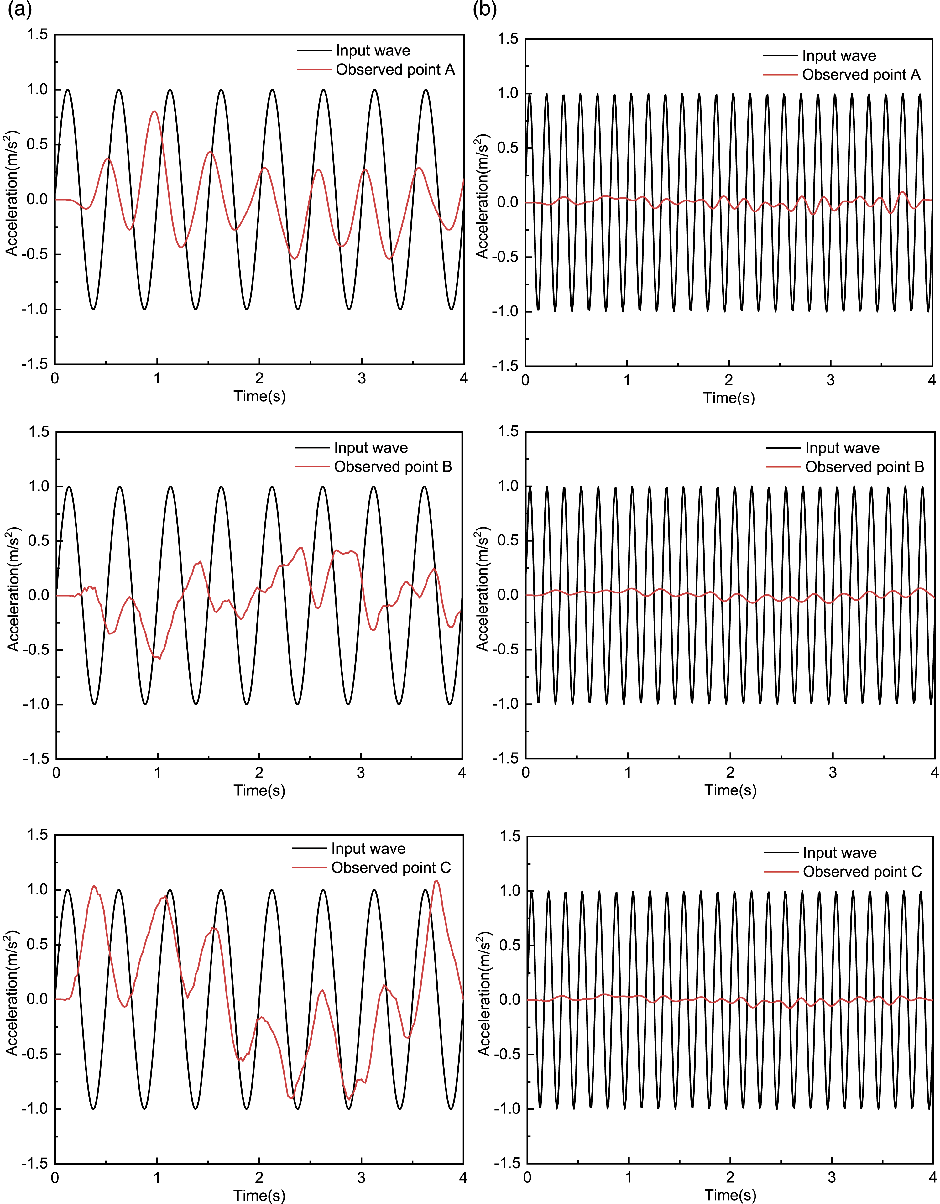
Seismic responses of the bridge systems
Seismic acceleration records.
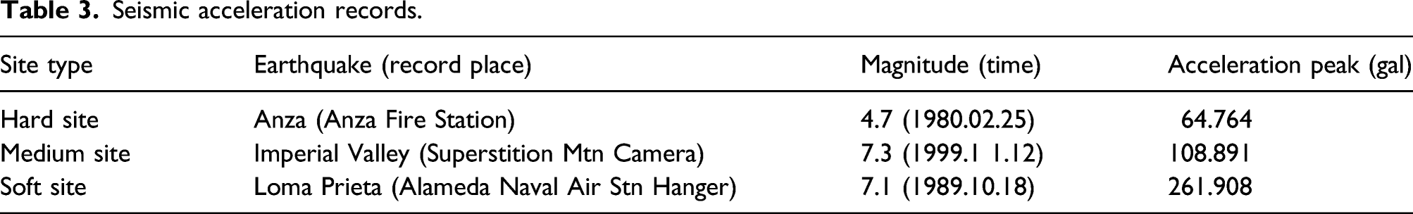
A full-time history analysis of the systems is carried out
The acceleration responses and their Fourier spectra at observed point A in the two kinds of systems under the action of the three seismic waves are shown in Figures 17(a)–17(c), respectively. Additionally, a comparison of the acceleration peak values of all the observed points is shown in Table 4. Acceleration time history curves and their Fourier spectra of point A under the action of three seismic waves: (a) Anza, (b) Imperial Valley and (c) Loma Prieta, where CF and PIF represent the bridge structures with concrete foundation and with the proposed PIF, respectively. The acceleration peak values of the observed points under the action of three seismic waves.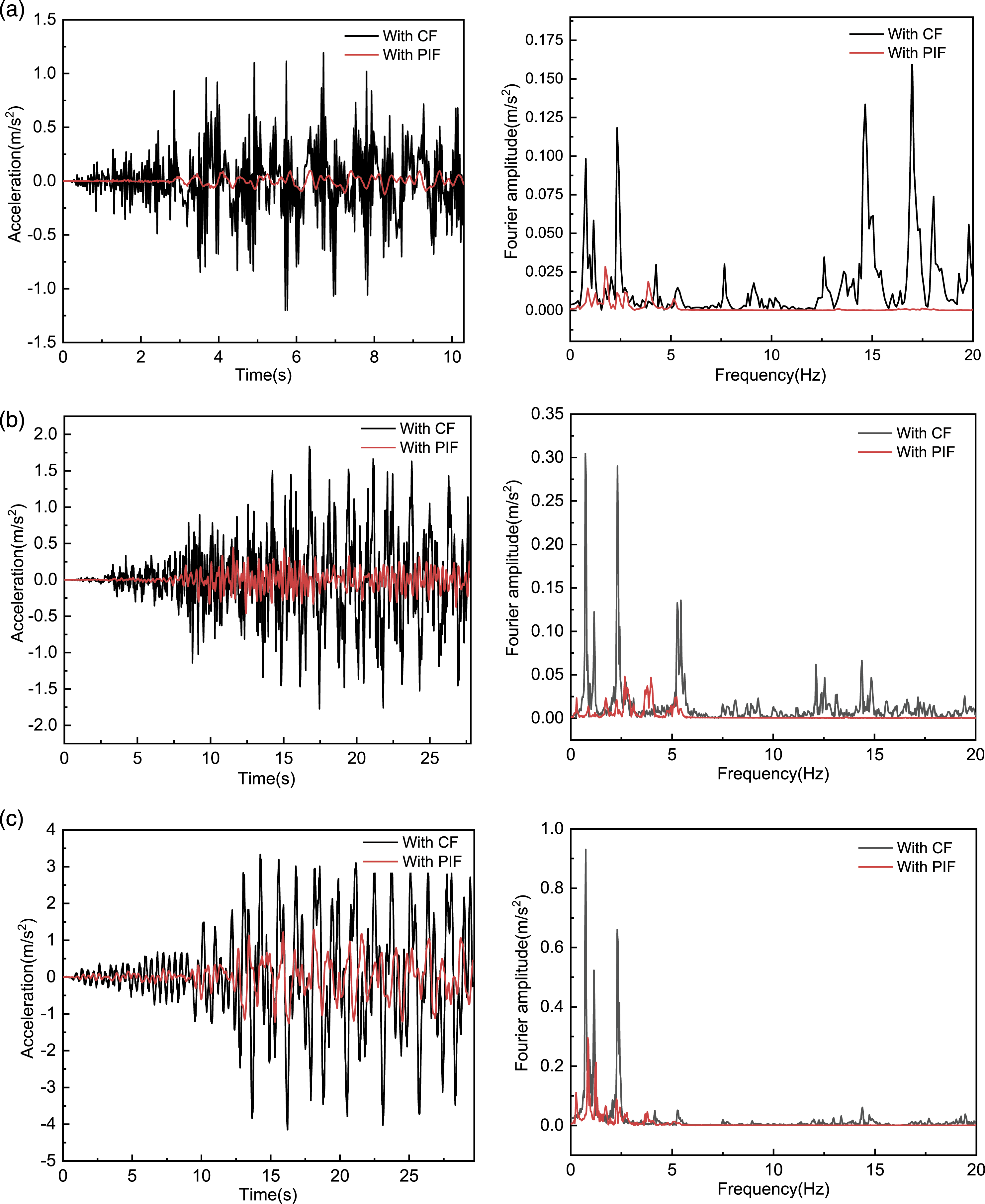

The acceleration responses of different observed points with the proposed PIF are all significantly smaller than those with the CF under the action of three different site types of seismic waves, which proves the superiority of the proposed PIF in terms of seismic isolation performance. In addition, for the same observed point A, B or C, compared with that of the CF, the structure with the proposed PIF has a larger reduction percentage under the action of Anza waves but has a smaller reduction percentage under the action of Loma Prieta waves. This slight difference in attenuation performance for these seismic waves can be explained by the fact that the dominant frequencies of these three seismic waves covered by the designed AZ are slightly different and that the PIF exhibits better filtering performance if more dominant frequencies are located in the AZs. Moreover, under the action of the same seismic wave, the responses of observed point C exhibit the largest reduction percentage of the three points. This can be explained by the fact that the observed point C is located on the cantilever bridge deck and that the response at this location is larger than those of other locations on the bridge deck. The isolation performance of the proposed PIF is more obvious at this location.
It is noted that the economic benefits and construction feasibility should be taken into account when considering the length of proposed PIF along vertical direction in practical applications. The similar simulation conducted by us demonstrated the proposed PIF also has superior isolation performance for the vertical incidence of seismic waves compared with the CF. The proposed PIF is proven a promising option for seismic reduction of engineering structures in practice.
Conclusion
In this paper, a new type of PIF is proposed through the topology optimization of the smallest periodic unit, and the analysis shows that the PIF can be used as an effective filter to isolate different site types of seismic waves. Different from traditional isolation systems such as friction bearings, lead rubber bearings and high damping rubber bearings, the isolation mechanism of the proposed PIF is a result of its AZs. The objective of this study is to search for the ideal AZs to adapt to more earthquake conditions and to promote applications in engineering seismic control. The main conclusions drawn are as follows: (1) Optimized unit A, with a broad AZ, and optimized unit B, with a low-frequency AZ, are obtained by unconstrained and constrained GAs, respectively. The obtained AZ in the proposed PIF is approximately the superposition of the AZs of the optimized unit A and optimized unit B. (2) The proposed PIF of finite size is also effective for the attenuation of seismic waves, and the attenuation ability increases with an increasing number of units on the propagation path. (3) The sweep frequency shake test of a scale PIF specimen verifies the correctness of the AZ calculated by the FEM. The constant frequency shake tests show that the propagation of elastic waves whose frequency falls into the AZ can be suppressed, while those outside the AZ cannot be effectively isolated and can even be amplified. (4) Dynamic analyses demonstrate that for the same upper bridge structure, the proposed PIF shows better seismic isolation performance than the CF under the action of three different site types of seismic waves.
It is hoped that the adopted optimization program and the proposed PIF can inspire the design and study of novel isolation foundations that can be used to isolate earthquakes or environmental vibrations in civil engineering.
Footnotes
Declaration of conflicting interests
The author(s) declared no potential conflicts of interest with respect to the research, authorship, and/or publication of this article.
Funding
The author(s) disclosed receipt of the following financial support for the research, authorship, and/or publication of this article: This work was supported by the National Natural Science Foundation of China (Grant number 51878151 and 51808208).