
Abstract
The threat of terrorist bombing attacks on critical infrastructure has attracted a lot of attentions over the past decades. Contact explosion with a small explosive charge mass can cause severe damage to RC columns. Since columns are the primary load-bearing components in structures, the failure of critical columns can initiate collapse of the entire structure and result in devastating consequences associate with significant casualties and economic losses. To prevent catastrophic structural collapse, the most critical requirement of blast-damaged columns would be the residual capacity to withstand axial load. In this study, the residual axial load-carrying capacity of RC columns damaged by contact explosions was numerically investigated. A high-fidelity physics-based numerical model of RC columns under contact explosions was developed using the non-linear dynamic analysis program LS-DYNA with Arbitrary-Lagrangian–Eulerian (ALE) and Fluid-Structure Interaction (FSI) algorithms. The numerical model was comprehensively validated with existing experimental results in literature. An extensive parametric study was carried out to determine the effect of critical design parameters, including explosive charge mass, column diameter, longitudinal reinforcement ratio, and transverse reinforcement ratio on the residual axial load-carrying capacity of RC columns after contact explosions. The damage degree of the blast-damaged columns was quantitatively analyzed with a damage criterion based on the residual axial load-carrying capacity. Based on the parametric analysis results, an empirical formula was developed through multivariable regression analysis method for prediction of the damage degree and residual axial load-carrying capacity of blast-damaged RC columns under contact explosions. The proposed empirical formula can be utilized in preliminary design of RC columns against contact explosions and failure risk assessment of RC columns after contact explosions.
Keywords
Introduction
The past few decades have witnessed an increasing threat of terrorist attacks all around the world (START, 2018). Terrorist bombing attacks to critical infrastructures could result in tremendous casualties and economic loss and enormous social impacts, which have become one of the main means employed by terrorists. In an increasingly hostile global environment, protecting critical structures from potential terrorist threats has become an important course. More and more attentions have therefore been drawn to understand the vulnerability of critical infrastructure subjected to extreme blast loads in recent years (Draganić et al., 2019; Hao et al., 2016; Seible et al., 2008; Stewart et al., 2006). As seen in past terrorist attacks, detonation of improvised explosive devices (IEDs), such as suicide bomb, suitcase bomb, and car bomb, is one of the common attack methods utilized by terrorists. In particular, man-portable IEDs like suitcase and backpack bombs are quick to fabricate, convenient to carry and easy to camouflage, which was frequently employed in the past terrorist attacks. The threats of man-portable IEDs placed very close-in or directly contact with structural columns should deserve sufficient attention since contact detonations even with small explosive masses could result in severe damage to the targets (Dua et al., 2020a; Li et al., 2020).
Within a structure envelop, load-bearing column is commonly considered as the most crucial structural component and probably the most vulnerable component to terrorist bombing attacks. The failure of critical structural columns can lead to partial collapse or even progressive collapse of the entire structure. As exemplified by the Alfred P. Murrah Federal Building bombing in 1995 (Crawford 2013), the attack initially damaged a couple of primary load-bearing columns, which ultimately led to the collapse of about half of the building’s structure. A large number of fatalities were claimed, where over 85% of the people were killed not by the direct air blast wave but by the subsequent collapse of the building. An understanding of the response of columns subject to explosive devices placed in contact or very near-contact is critically important. Several experimental studies have been carried to investigate the dynamic behavior of reinforced concrete (RC) columns under blast loading. Williamson et al. (2011a, 2011b) conducted field tests on ten half-scale RC columns subjected to blast loads at various scaled distances to identify the failure modes and damage limit states of RC columns under blast loadings. Design and detailing guidelines for improving the blast performance of RC columns were proposed. Fujikura and Bruneau (2011) carried out an experimental investigation on the blast performance of circular RC columns with seismic design and detailing under close-in explosion. Yuan et al. (2017) performed field tests on two RC columns with circular and square cross-sections under contact explosions and the failure mechanism of the RC columns was numerically investigated. Later in the experimental studies conducted by Braimah and Siba (2018) and Chen et al. (2019), the effects of near-field or close-in explosions on square RC columns were investigated. Many researchers (Abladey and Braimah, 2014; Kyei and Braimah, 2017; Li and Hao, 2014; Rajkumar et al., 2020) have carried out numerical studies to investigate the blast response of RC columns using high-fidelity physics-based computer programs and conducted extensive parametric analyses to determine the influence of key critical design parameters on the behavior of RC columns under blast loading.
The most critical performance measure of a blast-damage column is the ability to withstand the axial load from the supported superstructure. Shi et al. (2008) proposed a damage criterion based on residual axial load-carrying capacity for quantifying the damage degree of RC columns subjected to blast loading and numerically developed pressure-impulse (P-I) curves for damage assessment. Echevarria et al. (2016) experimentally investigated the residual axial load-carrying capacity of circular RC columns and concrete-filled FRP tube (CFFT) columns subjected to close-in explosions. Chen et al. (2019) also conducted axial compression tests on square RC columns after close-in blast tests to evaluate the post-blast capacity of the blast-damaged columns. Bao and Li (2010), Wu et al. (2011) and Cui et al. (2015) numerically investigated the residual axial load-carrying capacity of square RC columns after close-in explosions. The previous studies primarily focused on RC columns with square cross-section and subjected to explosions at a certain distance. To the best knowledge of the authors, only limited studies have been carried out to quantify the residual axial load-carrying capacity of RC columns under contact explosions. Roller et al. (2013) experimentally investigated the post-blast axial load-carrying capacity of circular columns with normal strength concrete and advanced concrete materials. Most recently, Dua et al. (2020a, 2020b) conducted experimental and numerical investigations on the residual axial capacity of square and rectangular RC columns subjected to contact explosions. In general, there is still a research gap in understanding the residual axial load-carrying performance of RC columns with circular cross-section under contact explosions.
The present study focuses on providing insight into the residual axial load-carrying capacity of circular RC columns subjected to contact explosions. High-fidelity physical-based numerical models of RC columns under contact explosions were developed and comprehensively validated. With the validated numerical model, parametric studies were carried out to determine the effect of critical parameters, including explosive charge mass, column cross-section diameter, longitudinal reinforcement ratio, and transverse reinforcement ratio, on the post-blast residual axial load-carrying capacity of blast-damaged columns after contact explosions. Based on the parametric analysis results, an empirical formula was developed for evaluating the damage degree of RC columns subjected to contact explosion.
Development of numerical model
The non-linear dynamic analysis program LS-DYNA is employed in the present study to explicitly model the dynamic response RC columns under contact explosions and subsequently to determine the residual axial load-carrying capacity of the blast-damaged columns. A Lagrangian approach is used for the RC column while an approach is used to model the contact explosive charge and surrounding air. The numerical modeling details including structural modeling, material models, strain rate effects, contact explosion, and analysis procedure will be presented in this section. The model validation results will be presented in Validation of numerical modeling techniques.
Numerical model description
A high-fidelity physical-based discrete model of the RC column was developed employed LS-DYNA (LSTC, 2015) in Lagrangian approach. The cover and core concrete of the RC column is modeled with 8-node constant stress solid elements and 2-node Hughes–Liu beam elements is used to model steel reinforcements. A detailed illustration of the numerical model used for this study is shown in Figure 1. Perfect bonding between the concrete and steel reinforcement is assumed by merging the identical nodes of the concrete and reinforcement meshes. This simplification is reasonable because the damage of RC columns under contact explosions is primarily caused by the stress wave propagating within the column where the global structural response is very small. Thus, the induced slippage in the bond interface between the concrete and steel reinforcements is negligible. The bottom end of the column is fully constrained to model a fixed support. The top end of the column is restrained against horizontal translation only (i.e., in the X and Y directions). Numerical model of RC column under contact explosion.
The contact explosion scenario in this study induces a strongly localized damage of the column, and the global response of the column is not decisive for the local damage pattern. Therefore, only a limited part of the air domain is modeled in this simulation to save computing resources. This modeling approach has been proven reasonable by Yuan et al. (2017) and Li et al. (2020). To eliminate the potential influence of blast wave reflection at the boundaries of the air domain, non-reflecting boundary conditions defined with the BOUNDARY_NON_REFLECTING card are applied to the top surface and side surfaces of the air domain. A rigid ground is set at the bottom surface of the air domain to account for the blast wave reflection from the ground.
Material models
Input parameters for concrete and steel material models.
The MAT_PIECEWISE_LINEAR_PLASTICITY (MAT_024) in LS-DYNA (LSTC, 2015) is adopted to model the steel reinforcements, which is an elasto-plastic material model and allows the incorporation of strain rate effect. A strain-based failure criterion can also be defined. The fully damaged elements will be deleted from the calculation when the plastic strain exceeds the defined strain threshold. The input material parameters of steel reinforcements in the numerical model are given in Table 1.
Strain rate effects
Structures under blast loadings respond at very high strain rates in the range of 100–104 s−1. The material properties of concrete and steel under high strain rate loading differs significantly from that under static or quasi-static loadings. The dynamic increase factor (DIF), which is defined as the ratio of dynamic to static strength, is commonly utilized to consider the strain rate effect on concrete and steel material. In this study, the DIF recommended by Comite Euro-International du Beton (CEB, 1993) is used for the compressive strength of concrete which is given by
CEB (1993) also recommends empirical formula of DIF for concrete tensile strength. However, it is commonly believed that the CEB’s formula tends to underestimate the TDIF compared with experimental results. Instead, the modified relation of TDIF by Malvar and Crawford (1998) is represented by
For the strain rate effect on the strength of steel reinforcement, the formula proposed by Malvar (1998) is utilized in the present study. The DIFs for the yield and ultimate strengths of steel reinforcements is determined by follows
Modeling of contact explosion
To accurately predict the responses of RC columns under contact explosions, the TNT explosives and surrounding air are modeled explicitly. The multi-material ALE approach is used to establish a numerical model that can consider the fluid-structure interaction between the RC column (simulated with Lagrangian mesh) and the air and explosive (simulated with ALE multi-material mesh). The penalty coupling algorithm provided by CONSTRAINED_LAGRANGE_IN_ SOLID card is employed to model the fluid-structure interaction between the column and air and explosion products.
The air is modeled with the material type 9 (MAT_NULL) and the linear polynomial EOS expressed as follows
Input parameters for air and TNT explosive.
The TNT explosive is typically modeled with the material type 8 (MAT_HIGH_EXPLOSIVE_BURN) and the Jones–Wilkins–Lee (JWL) equation for EOS. The high explosive material model requires density ρ0, detonation velocity D, Chapman-Jouguet pressure pCJ. The pressure generated with the detonation of the explosive is expressed as follows
Numerical analysis procedure
The numerical analyses in the parametric studies presented in the Parametric studies and discussion section are performed in two phases. In the first phase, the contact detonation process and the following interaction between blast wave and column are simulated to obtain the dynamic response of the column under contact explosion. Since the simulation is extremely time consuming to reaches a complete response, it is terminated when the vibration velocities of the column nodes are negligible (i.e., less than 0.1 m/s). In the second phase, axial compression loading analysis is continued on the damaged column with the full-restart algorithm in LS-DYNA (LSTC, 2015). The residual axial load-carrying capacity of the blast-damaged column is evaluated to quantify the blast vulnerability of the column. A gradually downward vertical displacement is applied to the top of the column until the column fails, and the corresponding reaction force at the bottom end of the column is recorded. By this displacement-controlled loading approach, the axial force versus displacement curve including the post-failure descending portion can be captured. A typical curve is shown in Figure 6. The peak reaction force in the axial force versus displacement curve is determined as the residual axial load-carrying capacity of the blast-damaged column (Nr in Figure 6). In addition, only the second phase is conducted to determine the ultimate axial load-carrying capacity of the respective undamaged column (Nu in Figure 6).
When subjected to contact explosion, the RC column could suffer substantial local damage with badly deteriorated concrete core without developing apparent deflection. Thus, it is difficult to evaluate the damage degree of a RC column after being subjected to contact explosion by conventional indexes such as column lateral deflection etc. Based on the numerical analysis, a damage index based on the residual axial load-carrying capacity of the blast-damaged column according to Shi et al. (2008) is introduced to quantitatively evaluate the damage degree and blast resistant performance of the RC column. The damage index (D) is defined as follows
Validation of numerical modeling techniques
Blast test of RC column subjected to contact explosion
The author’s research group has performed several tests to investigate the dynamic response of RC columns with circular cross-sections under contact explosions. The results from one of the field blast tests on a benchmark circular RC column (specimen S1) were reproduced using the developed numerical model, by which to validate the numerical modeling techniques used in the present study. The tested RC column has a vertical height of 3700 mm and a circular cross-section of 400 mm in diameter. The column had a longitudinal reinforcement of ten 12-mm diameter steel bars that uniformly placed along the circumference. Transverse reinforcements were formed with 8-mm diameter steel bars placed 150 mm apart which decreased to 100 mm within the 600 mm range of the top and bottom ends of the column. The geometry and cross-section details of specimen S1 are illustrated in Figure 2. A fixed support condition was modeled at the bottom of the column by a concrete footing with dimensions of 1 m × 1 m × 0.5 m. The top of the column was fixed to a reaction wall through a steel collar. A 1-kg TNT explosive charge was directly placed on the front surface of the column with a vertical distance of 330 mm from the column footing. The complete experimental setup is illustrated in Figure 3. Three accelerometers were placed on the rear face of the column to measure the column dynamic response histories, with vertical distances of 0.3 m (A1), 1.75 m (A2), and 3.3 m (A3) from the bottom of the column, respectively. Additional details and results of the field blast tests were provided in (Tang, 2016; Yuan et al., 2017; Zong et al., 2017). Geometry and reinforcement details of RC column specimen S1 (unit: mm). Photo of field blast test setup.

A numerical model was established to represent the field blast test of specimen S1 with the modeling methods described in the Development of numerical model section. The numerically predicted damage mode of the RC column is compared with the experimental observations in Figure 4. The numerical damage profile of the column is presented by fringe plot of concrete elements with a damage scaler ranging from 0 to 2. The fringe levels represent the element’s effective plastic strain which is the scaled damage measure in the KCC model. A value of 0 indicates no damage and a value of 2 indicates complete failure of the concrete elements where cracking, crushing or spalling damage has formed (LSTC, 2015). It can be seen from Figure 4 that the numerical prediction qualitatively matches well with experimental result. The simulation results show that the failure mechanism of column under contact explosion is dominated by localized damage in the region near the detonation point with the other part of the column remaining relatively intact, which is consistent with the field test results. Concrete crushing on the front face of the column is well-captured by the numerical simulation as shown in Figure 4(b), with the crushed height of concrete being 550 mm as compared to the experimental measured value 600 mm. Cover concrete spalling on the side elevation of the column is numerically predicted and shows good agreement to that observed in the test. Post-test examination into the tested column found that the aggregate and mortar in the localized damage region can be easily knocked off by hammer, which indicates the concrete core has suffered severe damage and retained low residual strength. Figure 4(b) displays the numerically simulated damage contour of three cross-sections at 0.25 m, 0.33 m, and 0.45 m to the bottom end of the column, which demonstrates severe damage of the concrete core and loss of axial load-carrying capacity. The results indicate that the numerical model developed with the selected material models and contact explosion effect modeling approaches can reasonably predict the damage behavior of RC column under contact explosion. Comparison of experimental observation and numerical prediction of column damage.
The column vibration response measured by the accelerometers in the test is compared to further validate the reliability of the numerical model. Due to the extremely high-intensive blast waves generated by the contact explosion, the A1 and A2 accelerometers were failed to record normal data therefore not presented herein. Figure 5 compares the experimentally measured and numerically simulated acceleration time histories of accelerometer A3. The comparison shows a good agreement, with the response characteristics such as the initial vibration time, the peak acceleration value and the attenuation trend obtained by the numerical simulation correlated well to the experimental results. Comparison of experimental and numerical acceleration history of A3.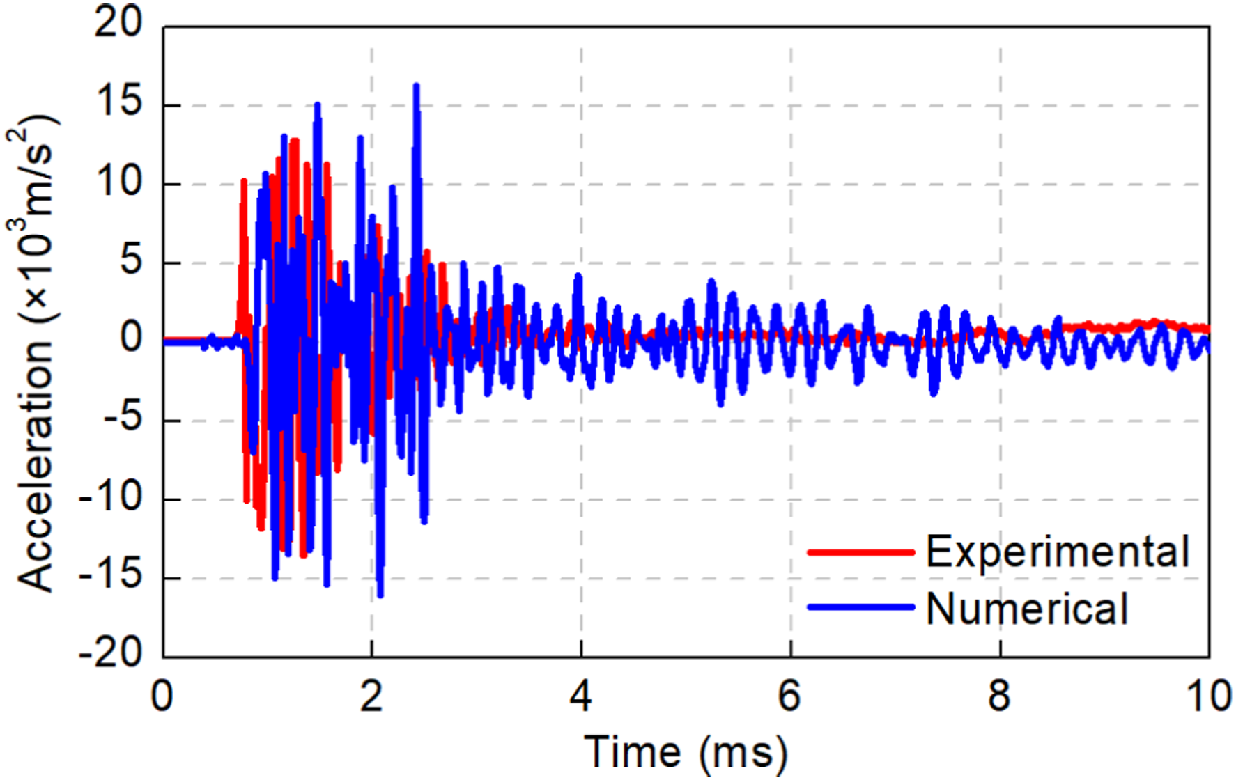
Axial compression loading analysis of RC column
Validation of the numerical analysis on the axial load-carrying capacity of RC columns was achieved by comparing simulation results against the nominal axial load-carrying capacity of the RC column determined with the analytical formula prescribed in China’s design code (Standardization Administration of China, 2010) as follows
Figure 6 shows the numerically predicted axial load versus displacement curve of the intact column S1 and the analytically determined ultimate axial load-carrying capacity with equation (8). The numerically determined ultimate axial load-carrying capacity is 4510 kN, which shows good agreement as compared to the analytically calculated axial load-carrying capacity (Nu,analytical) of 4273 kN with a variation of less than 6%. The validation analysis indicates that the numerical model developed with the material models and modeling techniques can predict the axial load-carrying capacity of a RC column with fair reasonable accuracy. Numerical axial load versus axial displacement curves for column S1 (RC1L1T1).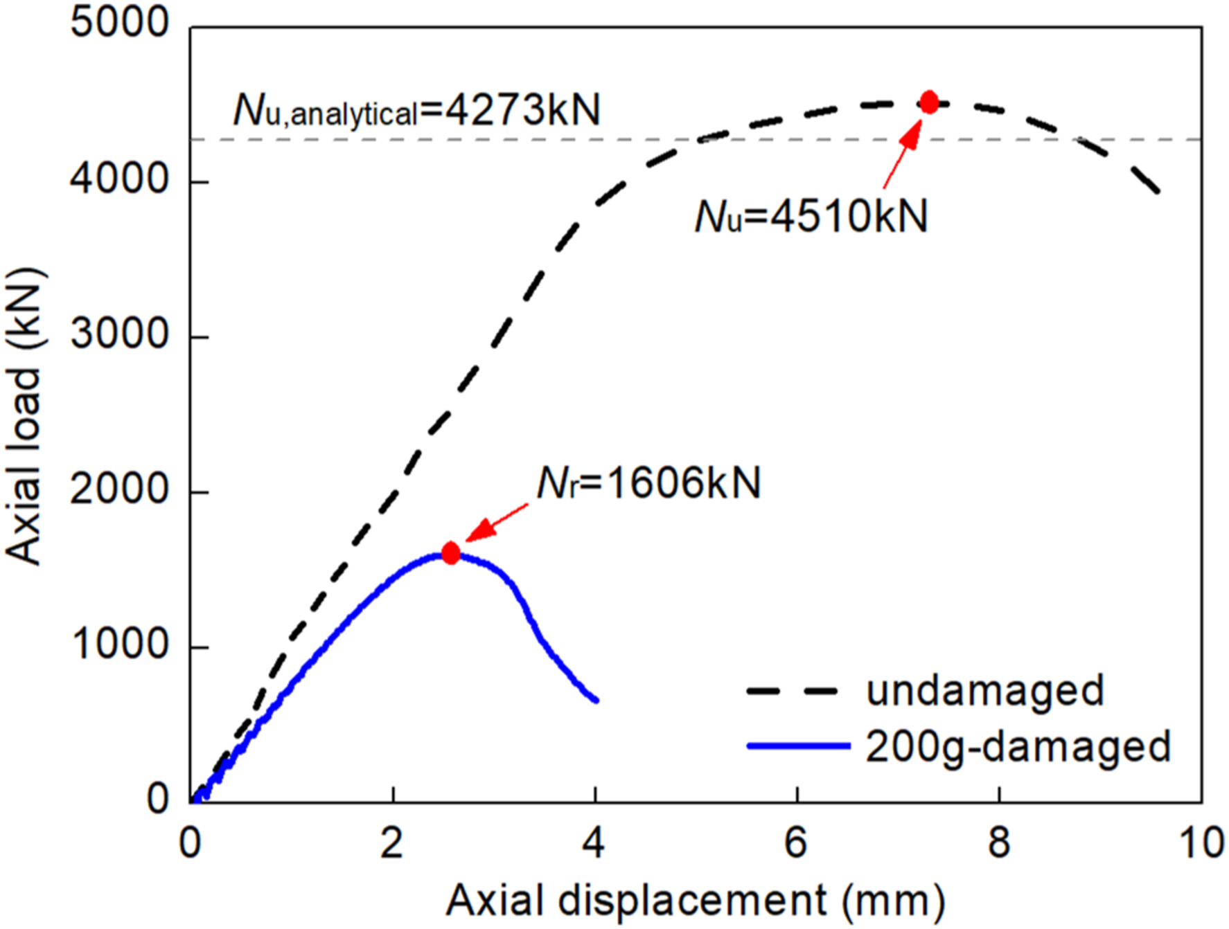
In general, based on the above comparison analyses, it is confident to believe that the numerical model developed with the selected material models, input parameters, and modeling techniques is reliable for predicting the blast response of RC columns under contact explosions and for estimating the residual axial load-carrying capacity of the blast-damaged columns.
Parametric studies and discussion
Numerical simulation matrix
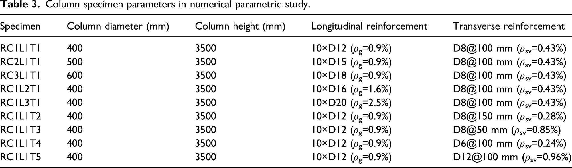
Column specimen parameters in numerical parametric study.
Effect of explosive mass
Damage degree of column RC1L1T1 under different blast scenarios.
Damage profiles of column RC1L1T1 under various blast scenarios: (a) BS1, (b) BS2, (c) BS3, (d) BS4, (e) BS5.
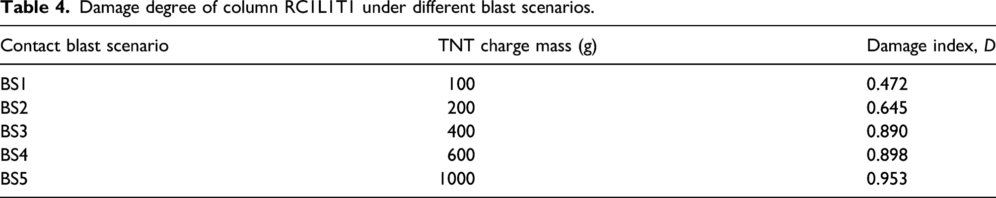
Table 4 presents the damage indexes of blast-damaged columns with different explosive charge masses, which shows the damage level significantly increasing with respect to the explosive mass. The damage degree increases from 0.47 to 0.89 when the explosive mass increases from 100 g to 400 g. Figure 8 shows the contribution ratio of the concrete and longitudinal reinforcements in carrying the axial load of the columns damaged by different blast scenarios. The axial load carrying by the concrete and longitudinal reinforcements of the blast-damaged columns is obtained from the numerical simulation by extracting the node forces of the two respective parts in the numerical model. It can be seen that approximately 80% of the column residual axial strength is contributed by the concrete part when the charge mass is less than 200 g, while this proportion decreases rapidly to only 15% when the charge mass further increases to 400 g. On the other hand, the contribution of longitudinal reinforcements to the residual axial capacity increases, with the proportion increases from only 10% to over 90% as the charge mass varies from 100 g to 1000 g. This is because when the charge mass is small, the concrete damage is not large and the residual axial strength of the damaged column is mainly provided by the remaining concrete core. With the charge mass increasing, more severe damage is resulted in the concrete which leads to more significant strength degradation. Therefore, the concrete part can retain relatively small residual axial load-bearing capacity. Contribution of concrete and longitudinal reinforcements to residual axial capacity of column RC1L1T1 under different blast scenarios.
By correlating the damage status of the columns in Figure 7 and the damage index in Table 4, it can be found that the damage degree of the column can be extremely large even when the observed concrete damage of RC columns are small. This is particularly evidenced in BS2 where only slight concrete crushing is observed on the frontal surface but the damage index of the column exceeds 0.6. This is because the blast induced stress wave propagated in the column can cause serious damage to the concrete core, though almost no spallation is observed due to the confinement of transverse reinforcements to the concrete core.
Effect of column diameter
Damage degree of RC columns with different column diameters.
Effect of longitudinal reinforcement ratio
In addition to the column section dimension, the longitudinal reinforcement ratio could also have an influence on the blast performance of RC columns. The effect of longitudinal reinforcement ratio is investigated by varying the size of the longitudinal steel bars from 12-mm diameter to 20-mm diameter with the reinforcement ratio ranging from 0.9% to 2.5%, as presented in Table 3. The column geometry and the transverse reinforcement arrangement are kept the same.
Damage degree of RC columns with different longitudinal reinforcement ratios.

Effect of transverse reinforcement ratio
When a RC column is subjected to contact explosion, the loss of column’s axial strength is primarily due to the concrete damage. The transverse reinforcements in a RC column can provide confinement to the concrete core and strengthen its plasticity and ductility. Therefore, transverse reinforcement ratio is expected to have a significant influence on the blast response of RC columns under contact explosions. The transverse reinforcement ratio can be varied in two methods, that is, the same transverse reinforcement size but different placement spacing, and the same transverse spacing but different transverse reinforcement sizes. For the former method, 8-mm diameter transverse reinforcement is used but the spacing is varied from 50 mm to 150 mm, while for the latter the same transverse reinforcement spacing of 100 mm is kept unchanged but the diameters of steel bars are varied by 6 mm, 8 mm, and 12 mm (as presented in Table 3).
Damage degree of RC columns with different transverse reinforcement spacing.
Damage degree of RC columns with different transverse reinforcement diameters.

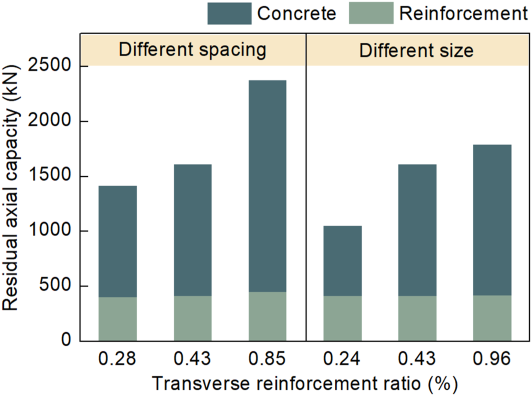
Effect of transverse reinforcement ratio on residual axial capacity of blast-damage columns.
Empirical formula for column damage assessment
The parametric study revealed the significance of different parameters that affect the residual axial load-carrying capacity of RC columns subjected to contact explosions. An empirical formula was therefore derived with multivariable regression fitting method for the assessment of column damage index in terms of TNT explosive mass, ultimate axial load-carrying capacity and transverse reinforcement ratio. The formula is expressed as follows
Figure 10 presents the comparisons of damage index between the formula predictions and the results of the numerical analyses. It is shown that the proposed formula can provide a reasonable prediction to the damage degree of RC columns after contact explosions. The proposed empirical formula can be utilized for preliminary analysis in the design of RC columns against contact explosions and rapid damage assessment of RC columns after being subjected to contact explosions. Comparisons of formula calculated damage index with numerical results.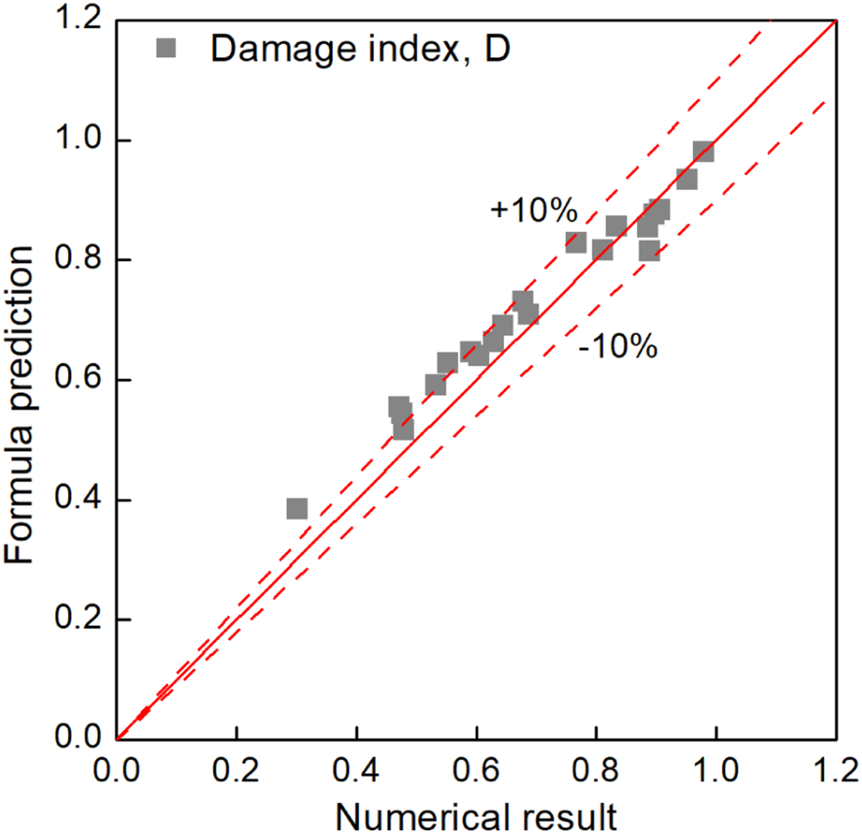
Conclusions
This paper conducted numerical investigations on evaluating the residual axial load-carrying performance of RC columns under contact explosions. A high-fidelity physical-based numerical model is developed and validated against existing test results, with which parametric analyses are carried out to evaluate the effect of critical design parameters on the blast performance and residual axial load-carrying capacity of RC columns after contact explosions. The following conclusions can be drawn based on the findings of this study.
RC columns are vulnerable to contact explosions. The damage mechanism of RC columns under contact explosions is dominated by localized damage in the vicinity of the charge location with the other part of the column remaining relatively intact. Under small explosive charge mass, only concrete on the front face of RC columns crushed. As the charge mass increases, concrete spalling occurs on the side and rear faces of RC columns.
A damage criterion based on the residual axial capacity of blast-damaged RC columns is employed to quantify the damage degree of the columns. The parametric analysis results indicate that the residual axial capacity of the blast-damaged column generally decreases with an increase in the column diameter, the longitudinal reinforcement ratio, and the transverse reinforcement ratio. Increasing the column diameter is identified to be the most effective in improving the residual axial capacity of the blast-damaged column. The effectiveness of an increase in the longitudinal reinforcement ratio is nevertheless limited. Increasing the transverse reinforcement ratio by reducing the placement spacing is more effective than by using transverse reinforcements with larger size in improving the residual capacity of blast-damaged RC columns to resist axial loads.
An empirical formula based on the parametric study results is derived using multivariable regression analysis method to predict the damage degree and residual axial capacity of RC columns after contact explosions. The empirical formula is demonstrated to be capable of assessing the residual axial capacity of blast-damaged columns with various parameters by comparing the formula predictions with the numerical analysis results. It can be used to for preliminary design of RC columns against contact explosions and for rapid damage assessment of RC columns after contact explosions. Further experimental investigation on the residual axial capacity of RC columns under contact explosions is desired due to the lack knowledge on this aspect.
Footnotes
Declaration of conflicting interests
The author(s) declared no potential conflicts of interest with respect to the research, authorship, and/or publication of this article.
Funding
The author(s) disclosed receipt of the following financial support for the research, authorship, and/or publication of this article: This work was supported by the China Postdoctoral Science Foundation (grant number 2020M681459); the National Natural Science Foundation of China (grant number 52008031) and the Fundamental Research Funds for the Central Universities.