
Abstract
When subjected to blast loading, brittle building components such as glass and masonry tend to break into fragments that are propelled at hazardous high velocities. There has been copious research on defining the design resistance of structures subjected to extreme dynamic loading, but research that relates the loading characteristics to fragmentation velocity and lethality is lacking in some areas. A review of research concerning fragmentation of brittle materials in dynamic loading scenarios, concentrating on far-field blast loading, was conducted. Fragmentation principles and their application in, analytical, statistical, numerical, and other varied modeling approaches were examined. Special attention was given to research evaluating fragment generation and velocity calculation above the level required for design of structural members and suitable for occupant hazard calculation. By surveying fragmentation research key factors that affect fragmentation behavior, velocity, and hazard across modeling efforts are developed and discussed.
Introduction
Much research has been undertaken surrounding the blast failure of civil structures and structural members. Understanding failure loads and accounting for different failure modes is critical to prediction and mitigation of structural failures due to blast loading. Subsequently, much research has been done to identify and predict the failure of structural members under blast loading. The goal of this research has been predominantly design focused, such as calculation of dynamic resistance of members, equivalent single degree of freedom models, strengthening of structures through additional ductility requirements, and advanced structural modeling approaches. Fragmentation of structural and non-structural members during blast loading generally falls outside of this design focus but it can still have a significant impact on occupant safety.
When structures experience extreme impulse loading they can fragment; brittle materials such as concrete, concrete masonry and glass are particularly susceptible. The dynamic pressures associated with blast loading can generate fragments with significant kinetic energies. Recently, there have been notable advancements in this field. The following is a survey of the methods that have been employed to understand the hazard posed by far-field blast fragmentation of civil structures. The goal of this survey effort is to use current and historical fragment hazard analyses to inform future research by noting critical considerations for any fragment hazard calculation, due to far-field blast loads. By examining the current fragment hazard research available in aggregate key factors that affect fragment hazard calculations are exposed.
Origins of fracture mechanics theory
The analysis of stresses in close proximity to an elliptical hole in a uniform material conducted by Inglis (1913) was instrumental in understanding the stress around a crack tip. Inglis (1913) modeled a crack as an elliptical hole (major axis 2a, minor axis 2b) in a plate with a uniform tensile stress perpendicular to the major axis of the ellipse as shown in Figure 1. Inglis (1913) showed that the stresses at a crack tip are significant and that as the ratio of a/b increases the stresses increase. Therefore, as crack length increases, stresses at the crack tip increase and continue to propagate the crack through the material. Elliptical hole in infinite plate.
Griffith (1921) applied the work done by Inglis (1913) to the unstable growth of a crack by using an energy balance to determine if crack extension would occur. Griffith (1921) theorized that fracture of a material would occur when the strain energy release rate during crack extension was greater than the surface energy increase of the material. By breaking glass rods in tension, Griffith (1921) validated the energy balance approach. Glass rods were used since their surface energy could be extrapolated from surface tension measurements made at high temperatures, and they behaved elastically until the moment of crack formation.
The Griffith (1921) crack theory could not be applied to metals since the theory could not incorporate energy dissipation due to plasticity. Irwin (1948) and Orowan (1956) both modified the Griffith methodology to incorporate the ductile behavior of metals during fracture. Mott (1945) also modified the Griffith methodology for dynamic fracture of brittle material, specifically the average fragment size of a ring being rapidly and uniformly expanded.
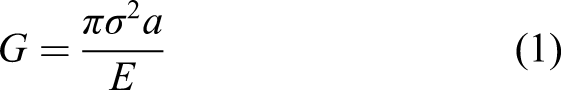
Irwin (1965) developed the energy release rate (G) fracture criteria. Fracture is defined as the point when the energy that produces crack growth is greater than the material resistance to crack growth. When a material fractures, the energy release rate (G) is equal to the critical energy release rate (G
c
). This gives a critical crack length and applied stress for a given material where crack growth will occur. For a crack of length 2a with an applied stress σ and a Young’s modulus of E as shown in Figure 1 the energy release rate is given by
As the field of fracture mechanics has matured it has been instrumental in many areas of solid mechanics. Advancements in fracture mechanics have been essential to defining dynamic fragmentation of brittle materials under high pressure loading. Numerous methods exist to describe the breakup of brittle materials under dynamic loading. Methods that describe brittle material fragmentation under highly dynamic loading fall roughly into three broad categories: (1) analytical methods, (2) statistical methods, and (3) numerical methods. Analytical methods follow the application of classical fracture mechanics to dynamic fragmentation problems. Statistical methods generate fragmentation data experimentally and use various curve-fitting techniques to match the fragmentation behavior observed and extrapolate those curves to other similar fragmentation events. Numerical methods use the finite element method in conjunction with various contact definitions and element release criteria to numerically simulate fragment generation of complex systems. Relevant research efforts in these three categorize are briefly summarized to illustrate the state-of-the-art and provide context for later discussion.
Analytical methods
Analytical methods derive their approach from the fundamental energy considerations of Inglis (1913), Griffith (1921), Mott (1945), and Irwin (1965). They provide generalized approaches to the problem of fragmentation; however, they generally only provide fragment size data and are difficult to apply to specific engineering applications. Many efforts have been made to modify energy approaches to real engineering fragmentation problems.
Grady (1982) used an equilibrium balance between interface energy and local inertial or kinetic energy that gives average fragment size. They compared their average fragment size calculations with data from oil shale fragmentation and explosive fragmentation of steel cylinders. They make the important observation that the total kinetic energy is not available for fragmentation. Only the portion of the kinetic energy that describes velocity relative to the center of mass of the fragment is available for fragmentation. The rest of the kinetic energy describes the rigid body translation of the fragment. Glenn and Chudnovsky (1986) modified this methodology to account for stored elastic strain energy. Usefulness of this approach is limited since it only allows for the calculation of a single nominal fragment size, and cannot account for inherent material flaws.
Grady and Kipp (1985b) explored the relationship between inherent flaw-based and energy-based fragmentation approaches. They argue that both energy concepts and flaw concepts should be incorporated into any fragmentation model. They used a numerical model of a rod fracturing in tension to illustrate the need for both methods of fragmentation. In materials with low concentrations of inherent flaws, they argue that the flaw distribution is critical. Conversely, they argue that energy considerations are significant when inherent flaw concentrations are high because not all flaws nucleate into full fragmentation points. This illustrates that both material disposition towards fragmentation and energy considerations are critical for formulating an adequate fragment model.
Glenn et al. (1986) created a model that unified the Grady (1982) and Griffith (1921) methods for calculating fragment size. This unification was accomplished by accounting for the finite velocity of fragmentation. The model gives the Griffith solution at low strain rates and the Grady solution at high strain rates.
Englman et al. (1988) derived a fragment distribution based on entropy maximization that agreed with the Grady solution. They note that most analytical formulation give only a single average or nominal fragment size. By using an entropy maximization approach they produce a distribution of fragment sizes. The maximum fragment size in the distribution corresponds to the nominal fragment size of the Grady solution.
Miller et al. (1999) used a cohesive surface numerical model to examine the validity of the Grady type energy balance methodologies. They show that by assuming that the fragmentation process is instantaneous, the energy-based methods over predict average fragment size. To improve correlation, the fragmentation process must be considered through time and the strength and distribution of internal flaws must be considered. Durgan (2001) subsequently derived two energy-based approaches for dynamic fragmentation. One model accounts for material flaws inherent in the material and the other one does not. Both models agree with the Grady solution at extremely high strain rates, but diverge at lower strain rates. Both models take the original analytical solutions and modify them to make them more applicable to real engineering scenarios. By accounting for the velocity of crack formation and inherent material flaws, they show that the Grady solution only applies to high strain rates.
Gommerstadt and Chudnovsky (2005) provide a thorough discussion on various fragmentation models and their relation to the Grady (1982) solution. They modified the methodology presented in Glenn et al. (1986) to account for more realistic crack speeds. The modification still provides a unification of the Griffith and Grady solutions. They also provided numerical and experimental data for comparison, and reasonable agreement was observed.
Zhang et al. (2003) developed a quantitative model to calculate the fragment distribution and size during dynamic fragmentation. They employ a second rank symmetric damage tensor to incorporate the effects of anisotropic damage. Their expression for the average fragment size is strain rate dependent. They compare their fracture stress and average fragment size calculations with fragmentation data from oil shale and observe good agreement. Their model gives fragment distributions for constant strain rates.
Zhang et al. (2004) and Zhang et al. (2006) formulated a model that calculates fragment size and ejection velocity. They use a damage model to formulate their fragment model. The ejection velocity is calculated by assuming that the elastic strain energy stored in the fragment after separation from the main body is converted into kinetic energy. They compare their fragment size calculations with those of Grady and Kipp (1980) and observe reasonable agreement. Outside of material properties, strain rate is the only independent variable that influences fragment size and velocity in their model.
Lu and Xu (2007) examined an internally loaded closed-box structure. They use an energy balance where concrete and reinforcing bars are accounted for explicitly in the resistive energy calculation. This is an extension of the work done by Xu and Lu (2006) where the venting of the structure is given more rigorous consideration. They separate the work done by the blast load into two parts: work done by the shock wave and work done by the overpressure. The work done by the overpressure is calculated using the impulse and mass of the wall. Strain rate strengthening is incorporated into the concrete material model. The venting of overpressure is also considered since the loading enclosure is closed-box structure.
Sung et al. (2020) used a single degree of freedom (SDOF) model to calculate the average fragment velocity of a reinforced concrete (RC) structure. They employ a similar experimental setup to Xu and Lu (2006) to validate their model. They use the same energy balance methodology as Lu and Xu (2007) but an SDOF model is used to calculate the resistance of the concrete member.
Many analytical methodologies have sought to determine the fragment size of a brittle material. They can account for the complex material interactions that are required to adequately describe a fragmentation event such as damage parameters, strain rate effects, and inherent flaw distributions. Most fail to capture the variability of fragment sizes observed during a dynamic fragmentation event since they only provide nominal or average fragment size calculations. These methods provide a strong basis for fragment models, but they can lack the flexibility to describe real engineering scenarios where fragment sizes are distributed and their velocity is required.
Statistical methods
Statistical methods provide a statistical distribution based approach to fragment models. By using data generated in experiments and fitting procedures, fragment size distribution and even velocity data can be calculated for particular loadings and structural systems. These methods account for the variability and complexity of the fragmentation processed via tuned statistical distributions and not modeling of physical behavior.
Grady and Kipp (1985a) discussed the characteristics of an adequate fragment distribution. They examined distributions based on geometric statistical fragmentation. Random points are arranged on a body with a Poisson distribution and various construction processes are used to draw lines through the random points. The lines connecting the random points are the boundaries of the created fragments. This process is continued until the desired number of fragments is reached. They show that the process used to construct lines have a significant impact on the final distribution of fragments, even when the initial point distribution are identical. Ultimately, they propose using a bilinear exponential distribution to describe fragment distributions in statistically inhomogeneous fragmentation scenarios.
Grady (1990) extended their examination of statistical fragmentation to bodies with finite extents and minimum fragments sizes. They provide experimental justification for their model with fragmentation data from a nuclear fragmentation event of a carbon and silver nucleus collision. They apply their fragment distribution to galaxy mass distributions to show the wide applicability of their method.
The random statistical fragmentation presented by Grady and Kipp (1985a) and Grady (1990) is based solely on principles of random statistics. The underlying fracture physics driving the fragmentation is not modeled. This gives the statistical methods of this type great flexibility since they are not restrained to particular materials or loading scenarios. The breadth of experiments used as validation in their methods attempt to show the overarching applicability of pure statistical fragmentation.
Zhang et al. (2014) conducted blast testing of various tempered glass panes to understand the fragmentation behavior of tempered glass. High-speed video was used to observe initial fragmentation and track fragments during flight to determine their velocity. Soft rags were placed behind the glass panes to aid in post-test fragment collection. To prevent further fragmentation of glass fragments after ground impact, a layer of soft clay with was placed downrange of the testing articles and the soft rags were placed on top of the clay. They note the impact of the negative phase pressure on fragment flight. Plots of fragment mass proportion and distance downrange were generated and compared for each experiment. Fragment size and reflected pressure were compared and they observed that fragment size decreases as reflected pressure increases. They compare back calculated velocities from range measurements to launch velocities observed via high-speed video and see reasonable agreement. The effects of drag and lift on fragment trajectory were neglected.
Ren and Xu (2017) examine the fragment distribution of concrete cylinders with fractal theory. A split-Hopkinson pressure bar (SHPB) was used to fracture each of the concrete specimens. The fragments were collected and sieved to generate a fragment distribution. Fractal theory was used to provide a more “precise indicator” of the fragmentation process. They show that concrete compressive strength and strain rate have an impact on the fractal dimension and subsequently the fragment size. They also point out that higher strain rates will completely pulverize the concrete, and lower strain rates will fail to fully fragment the concrete. From this, they argue that there is range of strain rates where this fractal behavior can be observed. They show that concrete compressive strength impacts fragment size. Fragmentation dependence on strain rate matches the observations of the analytical methods.
Bewick et al. (2017a) and Bewick et al. (2017b, 2018, 2019) conducted an extensive series of experiments examining the fragmentation of common construction materials. They dynamically fractured reinforced concrete, concrete masonry, and glass using shock tubes. Fragment data was captured by high-speed video and physical collection of fragments. High-speed video was used to document the initial cracking pattern before complete fragmentation, and an additional camera was used to capture fragment sizes and velocities during flight. Fragments were collected and a combination of sieving, shadowgraphy, and digital image processing was used to generate post-test fragment mass distributions. Various fitting procedures were used to generate best-fit lines for each fragment distribution.
This testing series observed that the mass distribution can change between post-test collection and mid-time observation via high-speed video. They also attempted to create fragment velocity distributions, but smoke and dust obscured velocity readings and made velocity values difficult to obtain. Two different distributions were observed to fit the data. Weibull distributions with an exponent of approximately 2/3 were observed for glass, concrete, and Concrete Masonry Units (CMUs). Rational power law distributions with exponents ranging from −5/6 to −7/6 were observed for tempered and annealed glass, concrete, CMU, brick, and clay tiles.
Keys and Clubley (2017b) used a shock tube to load unreinforced masonry walls constructed from frogged facing London bricks with no boundary conditions. The walls were not attached to the ground or a reaction structure. Dynamic loading was achieved with a shock tube and loading durations ranged from 150 ms to 200 ms similar to the durations observed in the work by Bewick et al. (2017a), and Bewick et al. (2017b, 2018, 2019). Fragments were observed with high-speed cameras and post-test fragments were collected. Their high-speed imagery was also obscured by dust and debris. Of the fragments recovered from the unenclosed experiment, 89% consisted of whole bricks.
Keys and Clubley (2017a) use blast testing of unrestrained masonry walls identical to those in Keys and Clubley (2017b) to develop a numerical model that calculates debris distributions. They observed that approximately 85%–90% of the fragments were undamaged bricks. The applied element method (AEM) was used to develop their numerical model. AEM is a numerical modeling approach that discretizes the structure into elements, which are connected by shear and normal springs along the element faces. The duration of the blast loading was roughly 10 ms, significantly shorter than the shock tube loading duration.
Schneider et al. (2020) used shock tube loading on an unreinforced masonry wall and stereo-camera high-speed video to determine fragment mass distribution and velocity profiles. They observed that most of the fragments were whole bricks, which is typical of unreinforced masonry (Magallanes et al., 2008). The stereo-camera method allowed the mass distribution to be calculated mid-flight before any fragments impacted the ground. Velocity distributions were also calculated through the entire loading since the camera setup allowed each fragment to be tracked from launch until ground impact.
Numerical methods
Numerical analysis of fragmentation allows for the full characterization of material behavior, fracture behavior, and loading. Most of the examined numerical models employ the Finite Element Method (FEM). Once a numerical model is validated against physical data, it can be used to calculate fragmentation behavior over a wide variety of loadings, physical configurations, and material properties without the need for costly and time-consuming physical testing.
Many varied methods exist that numerically describe the fracture mechanics and crack theory that apply to brittle materials. Zivkovic and Jovicic (2011) have a brief discussion of the Extended Finite Element Methods (XFEM) and Element Free Galerkin methods (EFG). Rabczuk (2012) gives an extensive review of advanced numerical methods used in brittle fracture. These advanced numerical methods may yield significant improvements in numerical descriptions of fragment mass and velocity calculations, since they can capture the complex physics inherent in fracture and crack growth. However, very little research has been done that applies these advanced methods to dynamic problems where fragment masses and velocities are sought. These methods are not examined in the current work since they lack research that compares calculated fragment mass distributions and velocities against experimental results
Dennis et al. (2002) conducted dynamic blast tests on quarter scale CMU walls to develop a finite element model that would match the experiment results. They modeled the CMUs as eight-node continuum elements and used a slide surface model with rigid connections to tie the CMUs together. The mortar was modeled as a zero-thickness contact surface. Both static and dynamic tests were conducted and wall responses were recorded. Their analyses emphasized that selecting material property values that reflect the actual material properties of the test article are critical but often difficult. The negative phase loading also had a significant impact on their results.
Eamon et al. (2004) used the finite element method to model the same quarter scale walls as Dennis et al. (2002). They used 8-node hexahedral elements with trilinear shape functions to model the CMUs. They also tracked fragment velocities inside the FEM framework and compared them to the fragment velocities observed in the experiment. They argue that wall and fragmentation behavior are sensitive to CMU material properties and observed high material sensitivity in their FEM results.
Eamon (2007) used the same FEM model described in Eamon et al. (2004) and conducted a sensitivity study to select random variables for a reliability analysis. Loads were idealized as four piece-wise linear functions with both a positive phase and a negative phase. Wall parameters used for the random variable sensitivity study included mortar joint modulus of rupture, contact friction between CMUs, friction between CMUs and supports, CMU Poisson ratio, compressive strength (f’c), tensile strength, modulus of elasticity, shear modulus, bulk modulus and strain rate strengthening. They found that the mortar modulus of rupture and contact surface friction had the greatest effect on wall behavior. They also observed that both the negative and positive phase pressures influenced wall behavior.
Wang et al. (2008) used a homogenized masonry wall material model and fracture mechanics to generate a numerical model of a brick wall. Fragment size distributions were generated via the model for different blast loads. Additionally, fragment range values were recorded. The effects of drag were included in the fragment trajectory.
Zhou and Hao (2009) created a mesoscale model for concrete fragmentation under contact blast loading. They placed spheres of aggregate in their model according to Fuller’s curve. The effects of damage and strain rate were incorporated into the mortar and aggregate strength criterion. Erosion techniques were used to simulate crack growth and produce fragments, which imposed a minimum fragment size limit of 2 mm. Both tensile strain and damage were used as erosion criteria. The numerical analysis illustrate that the distribution of aggregates has a significant effect on fragment distributions.
Wang et al. (2009) used an FEM model based on continuum damage and micro-crack development to calculate fragment size and velocity for a CMU wall. They model the CMU wall as a collection of bricks and joints and separately as a homogenized model. Relative agreement was observed between the homogenized model and the distinctive model. The generated fragment size distribution matches the Weibull distribution. They only model the blast load as a single triangular positive pulse.
Voort and Weerheijm (2013) combined a source function model with various empirical relations to generate expressions that describe the horizontal and vertical areal fragment densities. They validated their model with internal detonation tests of 8 m3 cubical RC structures. They found that fragment launch angle and drag can impact overall fragment trajectory. Similarly, Wu et al. (2019) employed a combined discrete element method (DEM) and finite element method (FEM) approach to numerical modeling of a fracturing RC structure subjected to an internal blast load. They also observe a significant reduction in fragment range when drag was included in their fragment flight model. Voort and Weerheijm (2013) observed fragment breakup at ground impact, which changed their observed fragment mass distribution. Fragments were also observed to ricochet and roll after impact, which skewed their calculated flight range. Research by Knock et al. (2004) investigated the bounce and roll of masonry debris, which studied post-impact behavior of masonry fragments on different materials. Xu et al. (2014) also examined the behavior of concrete fragment ricochet behavior. They developed an empirical model to determine if a given concrete fragment would ricochet off sand given a particular incident velocity and angle.
Hao (2015) used a homogenized masonry material model that incorporates material property modification with increased strain rates and damage. Fracture mechanics were employed to generate a fragment distribution using the same method as Wang et al. (2008). Only positive phase loading was used for blast load simulation. The impact of strain rate effects on wall response was investigated by comparing simulations with and without strain rate effects. They observed that strain rate effects had a significant impact on wall response when the scaled distance was approximately 5 m/kg1/3. They found that both the Weibull and Generalized Extreme Value size distributions could describe the fragment size distribution generated from their model.
Wu et al. (2019) employed a discrete element method (DEM) and finite element method (FEM) approach to numerical modeling of a fracturing RC structure subjected to an internal blast load. To reduce the computational cost, they conduct the trajectory modeling using a fast-running procedure that uses the fragment locations and velocity vectors when the overpressure reaches zero. The HJC material model was used for concrete, which includes strain rate effects and damage. Cohesive elements along element boundaries were used to model the fracture process. A bilinear traction separation law was used to dictate fracture along the element boundary. They note a distinct difference in fragment range when drag is included in the fragment flight calculation.
In any finite element based analysis mesh size and discretization play a critical role in model accuracy and stability. This numerical consideration can affect fragment mass and velocity calculations. Element size affects global model behavior but can also significantly impact crack location since many FEM based approaches only allow cracking along element boundaries. The work by Rabczuk (2012) has an extensive discussion on various meshing techniques and how they model cracking. Falk et al. (2001) discusses crack branching of cohesive elements is effected by mesh refinement. Discretization and meshing can have considerable effects on numerical models; however, those effects are not discussed in this work.
Key parameters
The following are observations regarding the fragmentation behavior of brittle solids, particularly in regard to velocity calculation of fragments for hazard analyses. Each of the analysis methods above has distinct advantages and limitations, by studying them in aggregate aspects of the fragmentation hazard problem that are critical for all analysis methods can be determined. These key properties and considerations should be given due consideration during any analysis of dynamic fragmentation and fragment velocity calculation. The goal of the following section is to illustrate important modeling and experimental considerations that should be given due consideration for any research that concerns the fragmentation hazard and behavior of brittle materials. Modeling considerations include: the effects of material properties on structural and fragment behavior, the influence of strain rate effects on structural and fragmentation behavior, and the effect of the negative pressure phase on energy calculations. Experimental considerations are the relationship between fragmentation behavior and loading duration, mid-flight fragment collisions, fragment breakup on ground impact, fragment ricochet and roll after impact, and drag effects on fragment trajectory.
The kinetic energy of fragments is typically used as an indication of fragment lethality. Fragment lethality calculations are quite complex because lethality is affected by fragment impact location and the possibility of penetrating fragments. Therefore, no in depth discussion on the potential lethality of fragments is conducted herein. The work by Ahlers (1969) provides a discussion on fragment lethality and plots that illustrate lethal combinations of fragment mass and velocity for different impact locations. To provide brief context, a fragment with a mass of 2 kg and velocity of 15 m/s has a lethality of 90% if it impacts the limbs or abdomen, according to Ahlers (1969).
Using material properties that reflect the actual behavior of in situ materials is critical. Numerical analyses of clay and concrete masonry walls have observed significant structural behavior variation due to small changes in material properties (Dennis et al., 2002; Eamon, 2007; Eamon et al., 2004; Wei and Stewart, 2010; Pandey and Bisht, 2014; Rafsanjani et al., 2015). Significant variation of material properties inside a single structural member is common for CMU walls (Melander and Conway, 1993; Melander et al., 1993). Eamon (2007) conducted a parameter study on a numerical model of a CMU wall and found that mortar tensile strength had a significant impact on wall behavior. Wei and Stewart (2010) use numerical modeling to examine clay masonry and observe that wall response is sensitive to changes in mortar strength. Pandey and Bisht (2014) have shown that mortar grade influences clay brick walls structural response. Through numerical modeling of a masonry wall under impact loading Rafsanjani et al. (2015) observed that wall displacement response is sensitive to changes in tension bond strength. These research efforts all suggest that the dynamic behavior of clay and concrete masonry walls is sensitive to the tensile strength, specifically of the mortar joint. The tensile strengths of the brick, mortar, and bond can be difficult to accurately obtain due to a number of different factors (Ahmad, 2018; Burnett et al., 2007; Dennis et al., 2002). When comparing a numerical or analytical model to data generated from an experiment it is critical that due consideration is given to the variability of the tension strength and bond strength of masonry. Not only is it highly variable and difficult to accurately measure, model results can be highly sensitive to its value.
The work by Zhou and Hao (2008), Zhou and Hao (2009), and Al-Salloum et al. (2015) suggest that fracture may be affected by aggregate distribution and composition. At low strain rates cracks do not pass through aggregate so the distribution of aggregates will affect fracture behavior since cracks must travel around the aggregate particles (Al-Salloum et al., 2015). Once the strain rate is high enough to initiate cracking through aggregates, the strength of aggregates against fracture will influence the fracture behavior of the concrete, since cracks will then propagate through the aggregate particles (Al-Salloum et al., 2015). Zhou and Hao (2008) compare a homogeneous numerical model and a mesoscale numerical model that discretely models aggregate particles and observed that the mesoscale model generated higher Dynamic Increase Factor (DIF) values. Both homogeneous and mesoscale models did have approximately the same transition point where DIF values increased significantly. Aggregate composition and distribution may affect the fracture properties of brittle materials. Materials with different aggregate structures like reinforced concrete, CMUs, and clay bricks, may exhibit different fracture behaviors due to their different aggregate structures. Material properties such as aggregate structure affect the fracture behavior of brittle materials.
Strain rate sensitivity of materials cannot be ignored. Much analytical work on fragmentation observed a relationship between fragment size and the strain rate (Gommerstadt and Chudnovsky, 2005; Grady, 1982; Grady and Kipp, 1985b; Durgan, 2001; Zhang et al., 2003, 2004, 2006; Zhou and Hao, 2009). Many researchers have used the Dynamic Increase Factor (DIF) as a method to account for strain rate effects on material properties. Much research has been conducted on concrete, concrete masonry, clay bricks, and mortar regarding proper implementation of DIFs (Al-Salloum et al., 2015; Burnett et al., 2007; Grote et al., 2001; Hao and Tarasov, 2008; Pereira and Paulo, 2017; Ross et al., 1989, 1995; Shi et al., 2021; Zhang et al., 2018; Zhou and Hao, 2008). The work by Malvar and Crawford (1998) summarizes many of the different methods used to calculate DIFs for concrete. Strain rate has been shown to have an influence on material properties of many common construction materials (Al-Salloum et al., 2015; Burnett et al., 2007; Hao and Tarasov, 2008; Malvar and Crawford, 1998; Pereira and Paulo, 2017; Ross et al., 1989, 1995; Shi et al., 2021; Sielicki and Lodygowski, 2019; Zhang et al., 2018; Zhou and Hao, 2008). It has been shown that variation in specific material properties can affect the structural response of CMU and clay brick walls to dynamic loading (Eamon, 2007; Pandey and Bisht, 2014; Rafsanjani et al., 2015; Wei and Stewart, 2010). The work by Hao (2015) shows that masonry wall response is sensitive to strain rate effects in specific scaled blast distances. Research on the change in tension strength of concrete at different strain rates has been well documented (Malvar and Crawford, 1998; Ross et al., 1989, 1995). Limited research has been conducted on the change in tension strength and bond strength of clay brick and mortar due to strain rate effects (Burnett et al., 2007; Shi et al., 2021). The observed DIF in tension for clay brick masonry may be partially due to the variation in bond strength and not due to an inherent material characteristic (Burnett et al., 2007). Since the tension strength of clay and concrete masonry materials has a pronounced effect on the structural behavior of masonry walls, the strain rate effects on masonry in tension likely have a disproportionate effect on wall failure (Eamon, 2007; Rafsanjani et al., 2015). Structural response of brittle materials can be sensitive to changes in material properties, especially tensile strength for clay and concrete masonry. Due to this sensitivity, the effect of strain rate on material properties should not be neglected.
The strain rate impact on material behavior has an impact on the fragmentation behavior of that material. Strain rate effects have been observed in the fracture behavior of laboratory specimens (Al-Salloum et al., 2015; Ren and Xu, 2017; Shi et al., 2021; Zhang et al., 2018; Zhou and Hao, 2008). Al-Salloum et al. (2015) used a Split-Hopkinson pressure bar (SHPB) test to examine the strain rate dependent behavior of concrete. They observed two distinct fracture behaviors at different strain rates; at a strain rate of 72 s−1 they observed fracture through concrete mortar only, and at a strain rate of 278 s−1 they observed that the mortar and aggregates had fractured catastrophically. The work by Ren and Xu (2017) shows that the strain rate has an impact on the fragmentation of a concrete cylinder. They used a SHPB to fracture concrete cylinders and observed that strain rate affected the fractal dimensions of fragments. Shi et al. (2021) examine the strain rate behavior of clay bricks using a SHPB, and a hydraulic testing machine. They observed higher degrees of fragmentation in specimens under higher strain rates in compressive experiments. Zhang et al. (2018) use an SHPB to examine the strain rate sensitivity of three different types of clay bricks; they observed increased fragmentation with increased strain rate. Zhou and Hao (2008) use numerical analysis to model concrete in a SHPB test and observe that fracture always occurs through the concrete Interfacial Transition Zone (ITZ) and that fracture is sensitive to strain rate. The observations in laboratory specimens that strain rate plays a role in dynamic fracture matches what is observed in the analytical work on fracture. In a brittle material under dynamic loading the strain rate should be considered when fracture phenomenon are important to the fragment response.
The velocity of fragmenting materials is tied to the energy imparted by the dynamic loading of the system. Ultimately, the energy imparted to the system drives fragment generation and results in fragments with significant kinetic energy. Lu and Xu (2007) and Sung et al. (2020) use the impulse as an effective way to calculate the energy of the system. Both Dennis et al. (2002) and Eamon et al. (2004) noted that the negative phase loading had an impact on CMU wall behavior. Zhang et al. (2014) noted a significant impact on glass fragment velocities by the negative pressure phase. The impact of the negative phase loading has been observed in other structural members as well (Dharani and Wei, 2004; Krauthammer and Altenberg, 2000; Rigby et al., 2014; Teich and Gebbeken, 2010). The negative pressure phase can have a significant impact on the reflected impulse on a given structure and therefore have an impact on the fragment velocity. As the reflected pressure rises to its peak the impulse also increases to its peak, but after this maximum the reflected pressure can fall to values below atmospheric pressure and the impulse falls in conjunction with the reduction in pressure. Figure 2 shows a typical pressure time history with the positive phase and negative phase indicated. This figure is not drawn to scale. The relationship between the positive and negative impulse can be found in DoD Department of Defense (2008). Typical Pressure Time History adapted from DoD (Department of Defense) (2008).

Negative phase impulse change.

The change in impulse between the positive and negative phase never falls below 30% and can be as large as 40%. This change in impulse between positive and negative phase illustrates a significant change in energy between states. Fragmentation analyses that are energy-based should consider the impact of the negative pressure phase on fragment velocity calculations. Shock tube loading should be examined closely in this regard. Due to their nature shock tube experiments generally lack a significant negative pressure phase. Without the energy reduction of the negative phase shock tube fragmentation results skew towards higher energy levels. This may result in larger degrees of fragmentation and higher fragment velocities when compared to a blast load with a similar peak pressure.
Two distinct fragmentation behaviors are observed during the dynamic loading of unreinforced masonry walls: (1) brick separation at mortar joints without significant fragmentation of bricks (Dennis et al., 2002; Eamon et al., 2004; Keys and Clubley, 2017a, 2017b; Schneider et al., 2020); and (2) fragmentation of bricks (Wang et al., 2009; Bewick et al., 2017a, 2017b, 2018, 2019). The peak pressures for both the Dennis et al. (2002) and Bewick et al. (2017b) CMU tests were approximately 0.4 MPa and 0.5 MPa, respectively. However, the positive loading durations were significantly different. Bewick et al. (2017b) CMU test 20 recorded approximately 100 ms of positive phase pressure duration. Dennis et al. (2002) test one recorded approximately 8 ms of positive phase duration. Limited pressure and impulse data for the Dennis et al. (2002) experiments was given in Baylot et al. (2005). Loading duration significantly affects fragmentation behavior of CMU walls.
By increasing the loading duration, the Bewick experiments achieved material level fragmentation of the CMUs in addition to the typical fragmentation along the mortar joints that is typically observed. This phenomenon is supported by the observations made by Grady and Kipp (1985b) and Durgan (2001) regarding the importance of flaw concentrations fragmentation modeling. The flaw distribution in CMU walls is complex and appears to have a primary and secondary level. During the short duration load, only the flaws at the mortar joints are activated. However, during long duration loading the flaws at the mortar joints and the flaws inherent in the CMUs are activated. When modeling fragmentation events great care must be taken to select an appropriate loading, peak pressure, and total impulse. Duration must also be considered since its impact on fragmentation is not trivial.
Collecting values of peak pressure and total impulse from different experiments yields some insight into the material level fragmentation observed in the Bewick et al. (2017b) experiments. Figure 3 shows the peak pressure and total impulse from the Bewick et al. (2017b) experiment, the Keys and Clubley (2017b) shock tube experiments, the Keys and Clubley (2017a) blast experiments, and the Schneider et al. (2020) shock tube experiments. When seen comparatively, the Bewick et al. (2017b) experiment has a significantly higher peak pressure and positive impulse than any of the other wall experiments. The impulse, which is a measure of the energy imparted to the system, was significantly larger than any of the other walls. This excess of energy likely caused activation of not only the “flaws” along the mortar joints, but also was great enough to activate the material level flaws inherent to the CMUs. This resulted in CMU breakup and the large fragment distribution observed. Impulse and peak pressure CMU experiments.
An important step in fragmentation modeling is validation of fragment size and velocity calculations. The nature of blast loading makes data collection during the blast event difficult, therefore most fragmentation data is collected after loading and fragmentation have occurred. The simplest method to validate fragment sizes is to collect and measure fragment sizes after the experiment has concluded. This allows for discrete measuring of fragments via sieve analysis or machine vision similar to the methods used by Zhang et al. (2014), Ren and Xu (2017), Keys and Clubley (2017b, 2017a), Bewick et al. (2017a), and Bewick et al. (2017b, 2018, 2019). However, post-test fragment collection cannot capture several phenomena that impact fragment mass and velocity distribution; (1) mid-flight fragment collisions, (2) fragmentation on ground impact, (3) fragment ricochet and roll after impact, and (4) drag on fragments during flight.
As fragments travel, they can impact other fragments and continue to breakup mid-flight (Bewick et al., 2017a, 2017b, 2018, 2019). The Bewick experiment series observed changes in the fragment mass distribution for glass between the early-time, mid-time, and late-time mass measurements. The fragment size distribution changes as the fragmentation event progresses, during the free flight of fragments. Methods to observe and measure fragment sizes and velocities mid-flight like those used by Bewick et al. (2017a), Bewick et al. (2017b, 2018, 2019), Schneider et al. (2020), and Zhang et al. (2014) provide a more accurate picture of the fragment hazard. They can develop a picture of the fragment hazard mid-flight and see how it changes during fragment flight. The fragment size distribution during flight can be different from the fragment size distribution observed on the ground.
When brittle fragments impact the ground or a structure at the end of their flight additional fragmentation can take place. Impact fragmentation was observed by Voort and Weerheijm (2013), Bewick et al. (2017a), and Bewick et al. (2017b, 2018, 2019). Zhang et al. (2014) attempted to reduce ground impact fragmentation by applying soft clay to the ground downrange of the specimens. Some research on close-in fragmentation of masonry and concrete has also employed soft clay and rags or tarps down range to reduce fragment breakup on impact (Shi et al., 2016, 2020). The rags were also printed with a grid so that fragments could be collected in bulk partitions and their general location recorded. The fragment distribution represented by post-test fragment collection may not represent the fragment distribution during flight because fragments can breakup on ground impact. Knock et al. (2004) observed that impact angles over 13° and fragment velocities over 18 m/s caused concrete spheres to fragment on impact with a hard surface. Ground impact skews fragment mass distributions towards higher numbers of less massive fragments. Methods similar to those used by Zhang et al. (2014), Shi et al. (2016), and Shi et al. (2020) could mitigate the effect of impact fragmentation on post-test fragment collection.
After ground impact, fragments may roll and ricochet, which will move them away from their impact location. When fragments are collected and logged during post-test collection they may not be at their impact locations. If fragment velocities or hazards are inferred from the final fragment locations they can result in higher inferred velocities, since ricochet carries fragments farther downrange from the initial impact location. Voort and Weerheijm (2013) observed fragment ricochet and roll, Knock et al. (2004) and Xu et al. (2014) both attempted to quantify the degree of fragment movement after impact. Knock et al. (2004) observed that ricochet is a function of both impact velocity and incident angle. High velocities and low incident angles are required for ricochet, low velocities result in fragment embedment and high incident angles result in fragment breakup. Post-impact movement poses a significant hurdle for any back calculated velocities based on post-test fragment location.
Drag can have an impact on fragment trajectory and final impact location if fragment velocities are sufficiently large. Low velocity fragments are not significantly affected by drag effects. Zhang et al. (2014) do not account for drag in their fragment velocity calculations. They observe fragment velocities around 20 m/s and see good agreement between the observed and calculated velocities. However, Voort and Weerheijm (2013) show that drag can impact fragment trajectory when fragment velocities are high. They show that without drag a 10 mm long fragment launched with a velocity of 80 m/s impacts the ground roughly 110 m from the origin. When drag effects are considered the impact location is reduced by roughly 60 m. Drag for high velocity fragments can have a significant impact on final fragment location.
Figure 4 shows how drag can impact fragment range. Fragment trajectories are calculated using the same procedure as Voort and Weerheijm (2013). The Newtonian drag model is used and the horizontal velocity is assumed to be much greater than the vertical velocity, so drag effects are neglected in the vertical direction. The drag coefficient (C
d
) is assumed to be 0.8 as suggested by Voort and Weerheijm (2013). The projectile is a sphere with a diameter of 0.3 m, cross sectional area of 0.0707 m2, and a mass of 14 kg, roughly equivalent to a single CMU. The fragment is launched horizontally from a height of 3 m. Fragment Trajectory with and without drag (Voort and Weerheijm 2013).
When fragmentation data is inferred from post-test collection of fragments due consideration should be given to fragment collisions, ground impact, ricochet, roll, and drag. If possible, methods to observe fragmentation mid-flight should be employed such as high-speed video similar to those used by Bewick et al. (2017a), Bewick et al. (2017b, 2018, 2019), and Schneider et al. (2020). High-speed video of the fragmentation event can show how prevalent mid-flight collisions and fragmentation are. Cameras that view likely ground impact locations will also allow for qualitative measurements of fragmentation due to impact, ricochet, and roll. Impact and mid-flight fragmentation appears to impact brittle materials more. High velocity fragments will be affected more by impact fragmentation, ricochet, roll, and drag. Consideration should be given to post-launch fragment behavior when any post-test collection of fragments is used, especially for brittle or high velocity fragments.
Conclusion
A broad survey of literature pertaining to fragmentation of materials under dynamic loading was conducted. Special attention was given to research that investigated fragment velocity calculation. There is a wealth of research on the dynamic fragmentation of materials. The work on fragment velocity calculation that would be suitable for fragment hazard calculations is not as mature as the general field of fracture mechanics. The research that does exist illustrates some key considerations and parameters that impact fragment velocity calculations.
By examining the existing research key factors that affect the dynamic fragmentation and hazard analysis of brittle materials were illustrated. Material properties are critical, insuring that modeling efforts implement the actual material properties of experimental specimens is critical. Strain rate impacts on material behavior can influence the fragmentation event and should not be neglected. Loading degree can affect fragmentation; materials such as CMU may experience two significantly different fragmentation behaviors at different loading regimes. The negative pressure phase can significantly reduce the energy available for fragmentation. Consideration should be given to the validity of shock tube loading since it generally lacks a significant negative phase. There are many phenomena that can influence fragment mass and velocity between the fragmentation event and post-test collection of fragments. These should be given due consideration and methods should be employed to quantify the influence these phenomena have, so that collected fragment data can be adjusted accordingly. These key parameters should be given due consideration for any fragment hazard analyses due to blast loading.
Future research on dynamic fragmentation of brittle materials should include examining how material properties vary inside test specimens and to what degree that inherent variability can affect experimental results. Research examining the fragmentation behavior of materials during long duration loading and short duration loading and to what degree similar fragmentation phenomenon are observed will help solidify the applicability of shock tube loading. Research on the surface roughness, and general fragment shape for brittle materials should be conducted to allow for more accurate modeling of drag effects on fragments. The effect of different fragment materials impacting on various potential surfaces should be examined to inform the potential of fragment ricochet, roll, and breakup on impact.
Footnotes
Acknowledgments
The lead author (J.E.H.) received support through the SMART fellowship from the U.S. Department of Defense, which provided valuable support and gave ample opportunity to receive guidance from highly knowledgeable individuals at the U. S. Army Engineer Research and Development Center (ERDC).
Declaration of conflicting interests
The author(s) declared no potential conflicts of interest with respect to the research, authorship, and/or publication of this article.
Funding
The author(s) received no financial support for the research, authorship, and/or publication of this article.