




Abstract
In this study, the flexural behaviour of lattice-web reinforced composite sandwich beams was investigated. The innovative composite sandwich beams consisted of glass fibre reinforced composite materials as the surface layer and web, Paulownia wood and South Pine as the core material. While keeping the external size unchanged, 1, 2, 3, 4 and 5 wood cores were formed by the vacuum infusion process at one time, to develop a different number of lattice-webs. In addition, the wood beam was used as a control. A four-point bending test was carried out on all specimen beams. The equivalent bending stiffness, equivalent shear stiffness, mid-span deflection of the specimens and bearing capacity were analysed. There is a larger plateau stage in the latter part of the load-midspan deflection curve of the beams strengthened by the lattice-web, which means the beams had ductile failure characteristics. Furthermore, the type of wood core greatly influenced the flexural behaviour of the composite sandwich beam, and the optimum lattice-web number of the Paulownia specimen is 2, and that of the South Pine specimen is 3.
Keywords
Introduction
Composite sandwich structures have been widely employed in aviation, military, transport, and civil applications for their unique characteristics, including their high specific bending stiffness, weight efficiency, structural designability and excellent corrosion resistance (Hollaway and Teng, 2008; Hassan et al., 2020; Ou et al., 2019, 2020). Currently, it has been increasingly difficult to meet the important multifunctional requirements in civil, marine and military engineering projects. Therefore, research focusing on composite sandwich structures is necessary in the present situation.
Composite sandwich members have been used as structural beams for roofing and floor slabs, floors, wall beams and bridge decks (Fang et al., 2019; Fernando et al., 2018; Miao et al., 2019). Commonly used foam and Balsa light wood core materials are soft, and are prone to sag when the local pressure substantially increases (Hou et al., 2020; Tuwair et al., 2016; CoDyre and Fam, 2016). Although the honeycomb or truss sandwich structure can withstand a greater pressure, the interfacial properties between the core and the facing are weaker due to the presence of a cavity (Lanssens et al., 2014; Correia et al., 2012; Ayrilmis et al., 2014). Therefore, in this paper, the use of Paulownia (PAW) wood and South Pine (SOP) wood as the core materials of the composite sandwich beam is proposed; these materials have excellent mechanical properties, such as shear resistance and compression resistance.
Manalo et al. (2010a) studied the flexural behaviour of composite sandwich beams with a glass fibre reinforced composite (GFRP) as the face sheet and modified phenolic foam as the core material; this beam was applied to railway sleeper structures. Wang et al. (2015) developed a simple and innovative sandwich beam with GFRP face sheets and a foam-GFRP web core. Satasivam and Bai (2014) presented a mechanically bolted modular assembly system of GFRP web-flange sandwich structures used for beam and slab applications. Fang et al. (2015) developed and studied innovative GFRP-bamboo-wood sandwich beams experimentally and by modelling.
In the early stages of our research, our group conducted related studies on composite sandwich beams and beams. Li et al. (2020) performed a three-point bending creep experiment on GFRP-balsa sandwich beams, and investigated the flexural creep behaviour of one-web and two-web reinforced GFRP-balsa sandwich beams. Qi et al. (2017) investigated the flexural behaviour of novel composite sandwich beams that feature a PAW or SOP wood core and GFRP face-skins reinforced with lattice-webs. Chen et al. (2018) conducted experimental and numerical analysis of the nonlinear flexural behaviour of lattice-web reinforced foam core composite sandwich beams. Zhu et al. (2018) investigated the bending behaviour of an innovative fibre reinforced polymer sandwich beam for application in a multistory building.
The lattice-web reinforced composite sandwich beam proposed in this paper is made by juxtaposing several wooden cores of the same wrapped fibre cloth in the horizontal direction (Gerber and Crews, 2009). The vacuum introduction of the resin allows the sheet to be integrally formed in the mould at one time, ensuring the integrity of the member and effectively improving the load carrying capacity of the sandwich beam. The bending test is carried out to study the influence of the number of lattice-webs and the type of wood on the bending properties of the composite sandwich beams.
Experimental programme
Test specimens
The test specimens were composed of a GFRP surface layer, a lattice-web and a wood core. The lattice-webs and surface layer were respectively wrapped with two layers of biaxial glass fibre cloths, and the areal density of the glass fibre cloths was 800 g/m2, as shown in Figure 1. The calculated thickness of each layer of fibre cloth and resin after curing was 1 mm. The height of the beam as the control group was 70 mm. The height of the other test specimens was set to 80 mm, the specimen width was 120 mm, and the length was 1400 mm. The details of each specimen are summarized in Table 1. Lattice-web reinforced composite sandwich beam. Descriptions of the specimens. Notes: The green frame represents the GFRP surface layer and the lattice-web. The test specimens “PAW” and “SOP” represents Paulownia wood and South Pine, respectively. The front numbers represent the number of core materials. “PAW” and “SOP” are all pure wood beams and are the control groups. “L" represents the length of the specimen. “B" represents the width of the specimen. “H" represents the height of the specimen.

Test material preparation
The wood core was cut into the required specifications, planed and slotted along the grain, as shown in Figure 2(a); the single core was wrapped with two layers of the (±45°) glass fibre cloth. After assembling multiple pieces of the core material, the whole periphery was wrapped with two layers of (0,90°) glass fibre cloths to form the surface layer (the 0-direction refers to the length direction along the test specimen), and the glass fibre cloths were as flat as possible. The starting point of the wrap was arbitrary, but was not located at the edge of the specimen. The finish point of the wrap was 5 cm above the starting point, which means that there was an overlap of 5 cm Preparation and manufacturing process of the sandwich composite beams: (a) sheet cutting and forming; (b) vacuum introduction operation; (c) arrangement of the fibre cloths; and (d) completion of specimen production.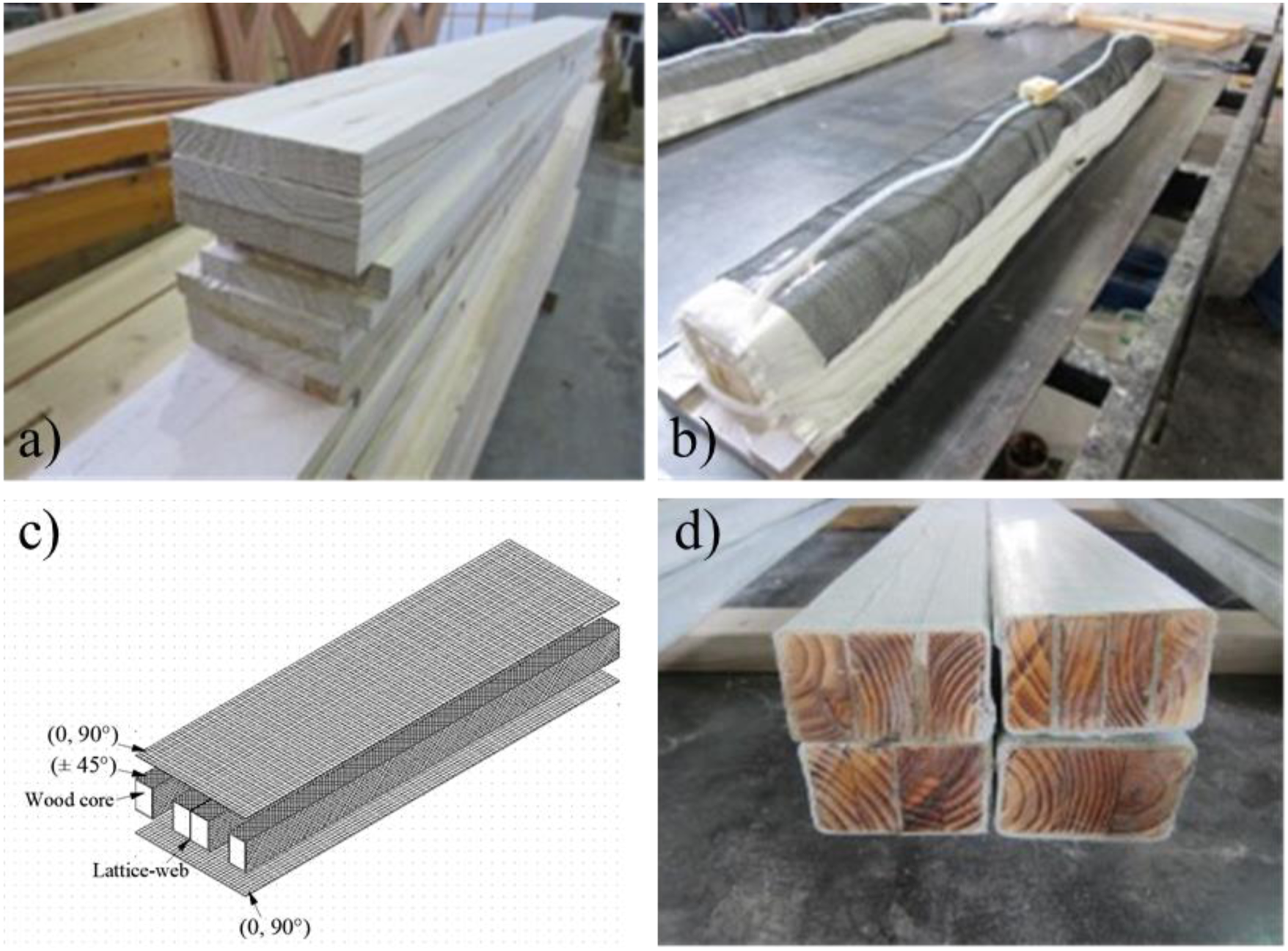
Test setup and instrumentation
The beam was subjected to four-point bending static loading, the distribution beam was arranged at two loading points, as shown in Figure 3(a), and the strain gauge was placed at the mid-span, front, bottom and loading points of the beam, as shown in Figure 3(b). Displacement and strain acquisition were performed using the DH3816N static strain test system. Experimental setup of the flexural behaviour of the beam: (a) schematic plot and (b) strain gauge arrangement.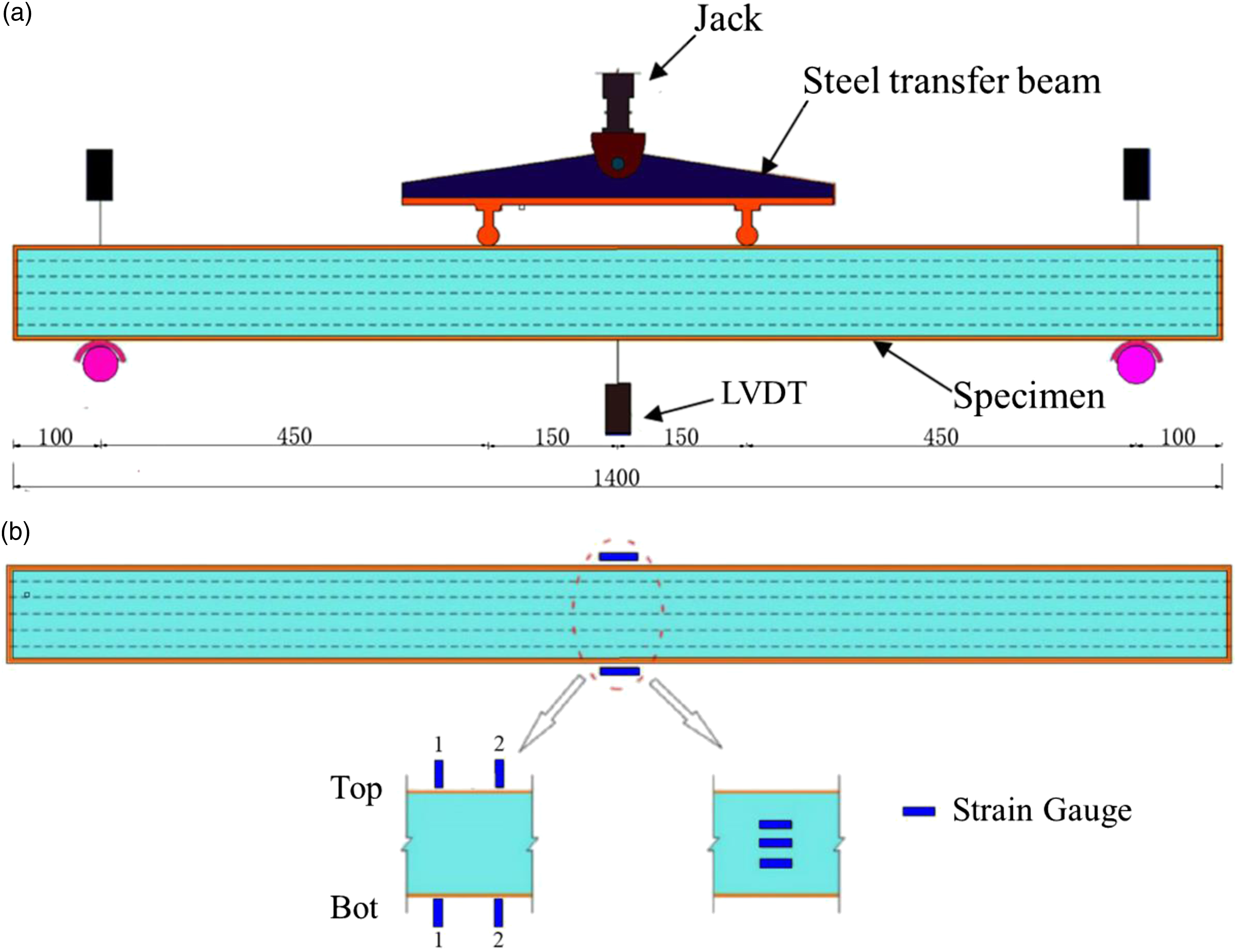
Experimental observation and results
Experimental observation
(1) Experimental observation of the Paulownia wood composite sandwich beam
For the pure PAW wood specimen, the stiffness of the beam was small due to the lack of fibre composite wrapping on the outside, and the deflection increased rapidly due to the increasing load. When the load reached 9.30 kN, a cracking sound was heard, and the crack in the specimen is shown in Figure 4(a). The fracturing of the specimen was the result of brittle failure. Bending failure modes of the wood core composite beam: (a) failure mode of PAW; (b) 1PAW failure mode; (c) 2PAW failure mode; (d) 3PAW failure mode; (e) 4PAW failure mode; and (f) 5PAW failure mode.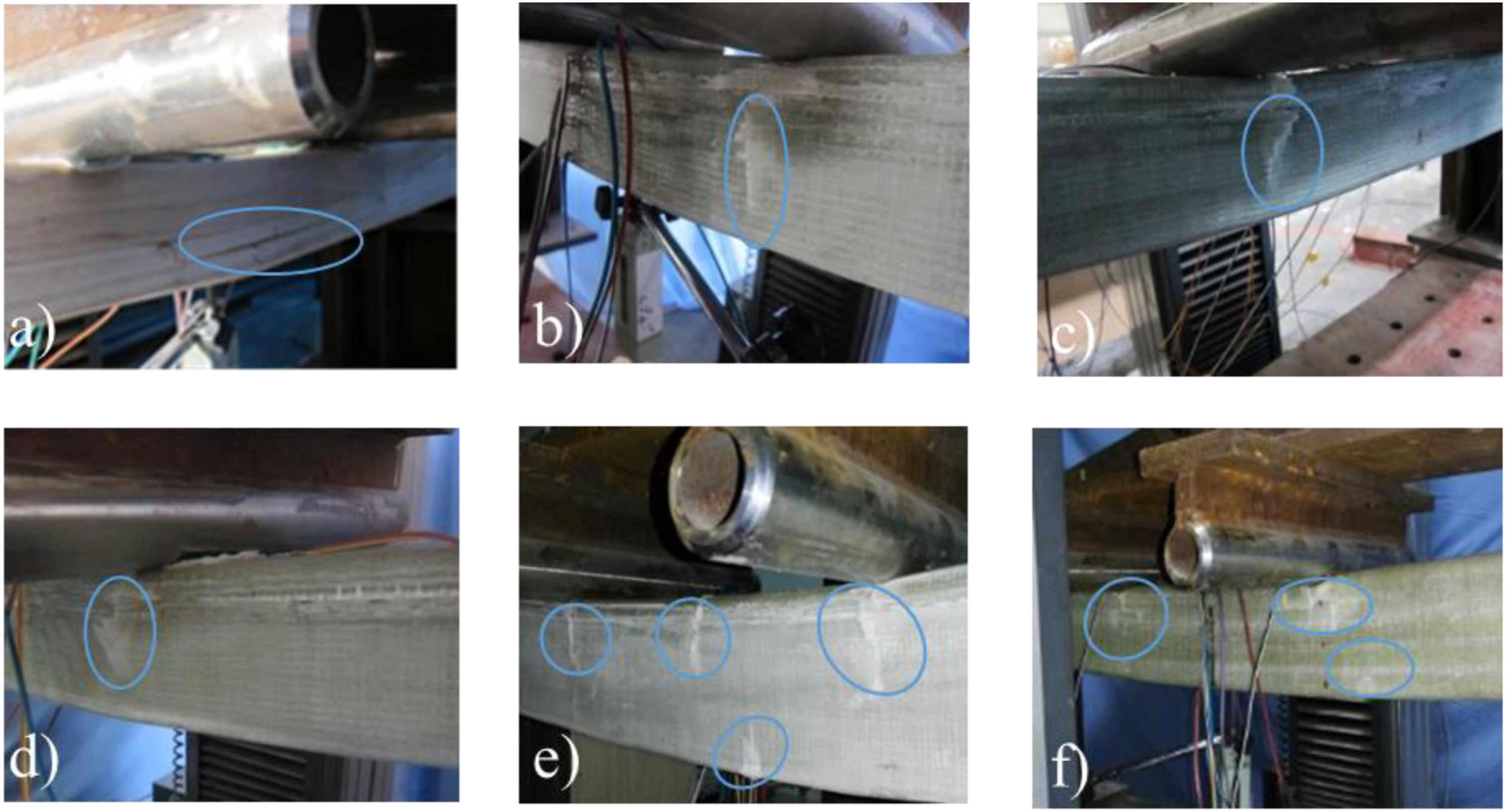
For specimen 1PAW, when the load increased to 19.7 kN, a slight tearing sound was heard. When the load climbed to 22.5 kN, the tearing sound of the glass fibre cloth was transmitted from the specimen. The fibre was whitened and cracked at the lower position of the loading point. The crack extended vertically downward with the deflection of the specimen as shown in Figure 4(b). The maximum bearing capacity of the beam was 24.7 kN. After that, although the deflection of the beam continued to increase, the bearing capacity of the beam decreased, and the final shear failure occurred at the loading points at both ends. The ultimate load and corresponding deflection of the specimens 2PAW, 3PAW, 4PAW and 5PAW were 34.3 kN, 46.7 mm; 31.65 kN, 39.84 mm; 29.3 kN, 43.79 mm and 20.18 kN, 27.9 mm, respectively. The experimental observation of the other four specimens are similar to those of 1PAW. The increase in load caused the mid-span deflection of the beam to gradually increase, and a small tearing sound was heard from time to time. When the load reached a certain value, a large amount of noise was heard. The fibre was whitened, cracked and extended downward, as shown in Figure 4(c)–(f). As the displacement of the specimen continued to increase, the load of the specimen began to decline slowly. Eventually, shear failure occurred at the loading point of both ends, and the load stopped at that moment.
(2) Experimental observation of the South Pine composite sandwich beam
The experimental observation of the SOP sandwich beam were similar to those of the corresponding PAW sandwich beam. The sound accompanied by SOP failure was brittle failure; a tiny fibre cracking voice was heard when 1SOP, 2SOP, 3SOP, 4SOP and 5SOP were slowly loaded. As the load increased, the tearing sound became obvious, and then a loud noise was heard suddenly. There were cracks under the loading point, and then the cracks developed downward. Finally, the fibre at the lower edge of the beam at the loading point cracked.
Experimental results of Paulownia wood composite sandwich beam
The load-displacement curve of the PAW wood sandwich composite beam is shown in Figure 5. Among the PAW, 1PAW, 2PAW, 3PAW, 4PAW, and 5PAW specimens, the ultimate load of the specimen and the corresponding mid-span displacement are 9.3 kN, 22 mm; 24.7 kN, 37.1 mm; 34.3 kN, 46.7 mm; 31.65 kN, 39.84 mm; 29.3 kN, 43.79 mm; 26.15 kN, 27.9 mm respectively. Compared with the wooden beam, the ultimate bearing capacity of the wood core composite beam without the lattice and the wooden core composite beam with the lattice structure is obviously improved. The ultimate bearing capacity of the wood core composite beam without the lattice structure is 166.6% higher than that of the wooden beam. The maximum bearing capacity of the wood core composite beam with the lattice structure is increased by 38.9%, 28.3%, 18.6%, and 5.9%. Load-midspan deflection curve of the PAW wood core beam.
The load-strain curve of the PAW wood core composite beam is shown in Figure 6. Load-midspan strain curve of the PAW wood core beam.
Experimental results of the South Pine composite sandwich beam
The load-displacement curve of the SOP wood core composite beam is shown in Figure 7. The figure shows that the ultimate loads of SOP, 1SOP, 2SOP, 3SOP, 4SOP and 5SOP are 13.43 kN, 35.38 kN, 37.28 kN, 40.54 kN, 29.68 kN and 33.44 kN, respectively, and the corresponding mid-span displacements are 27.8 mm, 35.91 mm, 36.72 mm, 44.12 mm, 32.05 mm and 40.24 mm, respectively. The ultimate bearing capacity of the wood core composite beam without the lattice is greatly increased by 152.6% compared with that of the pure wood beam. The ultimate bearing capacity of 2SOP and 3SOP specimens with the lattice is increased by 5.4% and 14.6%, respectively, although the ultimate bearing capacity of 4SOP and 5SOP decreased by 16.1% and 5.5%, respectively, compared with that of 1SOP. Load-midspan strain curve of the SOP wood core beam.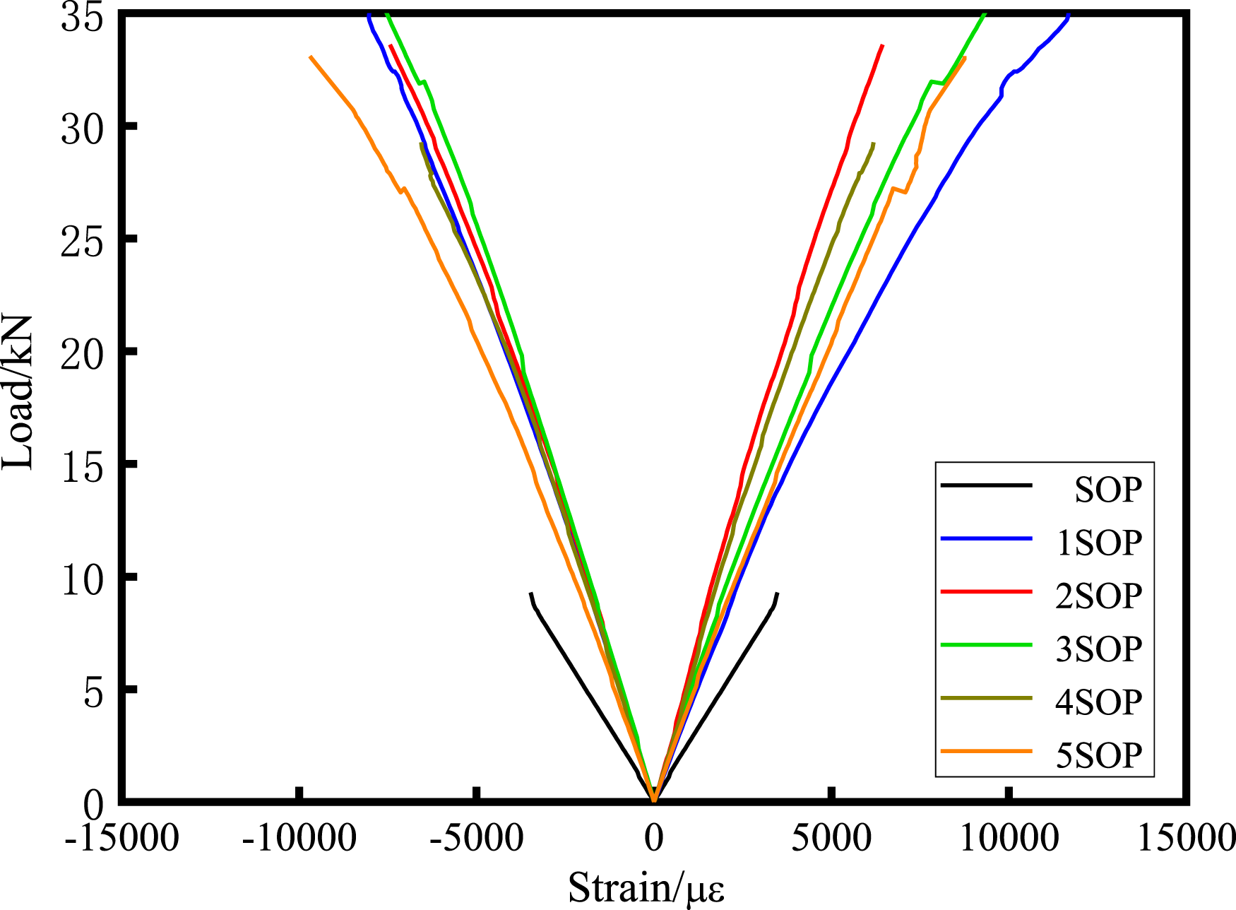
The load-strain curve of the SOP wood core composite beam is shown in Figure 7.
Test comparison
From a comparison of Figures 5 and 8, it can be seen that the ultimate load and deflection of the SOP wood core composite beam corresponding to the cross-section form are larger than those of the PAW wood core beam, in which the ultimate bearing capacity of the SOP beam is 44.41% higher than that of the PAW beam. The ultimate bearing capacity of the wood core composite beam with the lattice structure is increased by the greatest extent by 1SOP, and its ultimate bearing capacity is higher than that of the setting. The stiffness of the latticed wood core composite beam 1PAW is increased by 43.88%, and the test results of the SOP wood core composite beam are more ideal. From the load-midspan strain curves of Figures 6 and 7, it can be learned that the stiffness of the SOP wood core composite beam is greater, and the stiffness of the unrelated wood core composite beam 1SOP increased 54.55% compared to that of the unrelated wood core composite beam 1PAW. The stiffness of 1SOP is 45.31% higher than that of 1PAW, and the change in the stiffness is more obvious with the change in the lattice number. The composite sandwich beam with the largest number of lattice-web does not have the optimal bending performance. Based on the analysis of the curves, 3PAW has the largest stiffness in the PAW specimen, and 2SOP has the largest stiffness in the SOP specimen, which is not the maximum number of lattice-web for this kind of core material. Load-midspan deflection curve of the SOP wood core beam.
Theoretical analysis
Equivalent flexural stiffness
According to the plane section assumption, the flexural stiffness of the non-lattice wood core beam under compression is equal to the sum of the flexural stiffness of each part (Manalo et al., 2010b), as shown in Figure 9(a) Section of the specimens: (a) section of 1PAW; (b) section of 2PAW; and (c) section of 3PAW.

For the section of 2PAW (as shown in Figure 9(b))
For the 3PAW section (as shown in Figure 9(c))
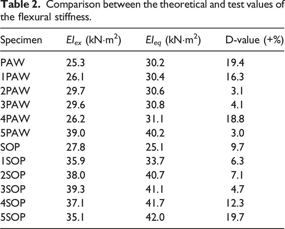
The same derivation process can be used for the lattice wood core beams with 4 or 5 layers of core material. The theoretical flexural stiffness formula can be summarized as
Comparison between the theoretical and test values of the flexural stiffness.
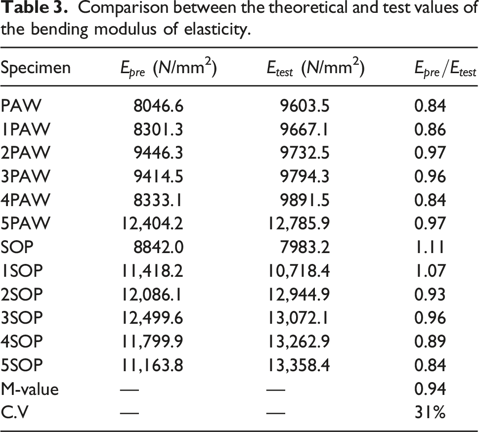
Comparison between the theoretical and test values of the bending modulus of elasticity.
Equivalent shear stiffness
Assuming that the sandwich acts like a Timoshenko beam, according to the first-order shear deformation theory, the basic assumptions are as follows: (1) the elastic analysis of small deformation is conducted; (2) the longitudinal and vertical compression deformation of core materials is not considered; (3) no relative slip between the core material and the beam is assumed; (4) the shear deformation of the beam is not considered; and (5) the deformation of core material meets the assumption of plane section.
The core material of the sandwich structure involved in this paper is semi-continuous in space, so it will be very tedious to solve it directly by numerical methods. At present, it is common to adopt the equivalent method to deal with the calculation of the sandwich structure with wood core material. The core material is considered to be equivalent according to certain principles to obtain a homogeneous and continuous core material (Manalo et al., 2010c). It is convenient to use the classical sandwich beam theory to solve the questions in this way.
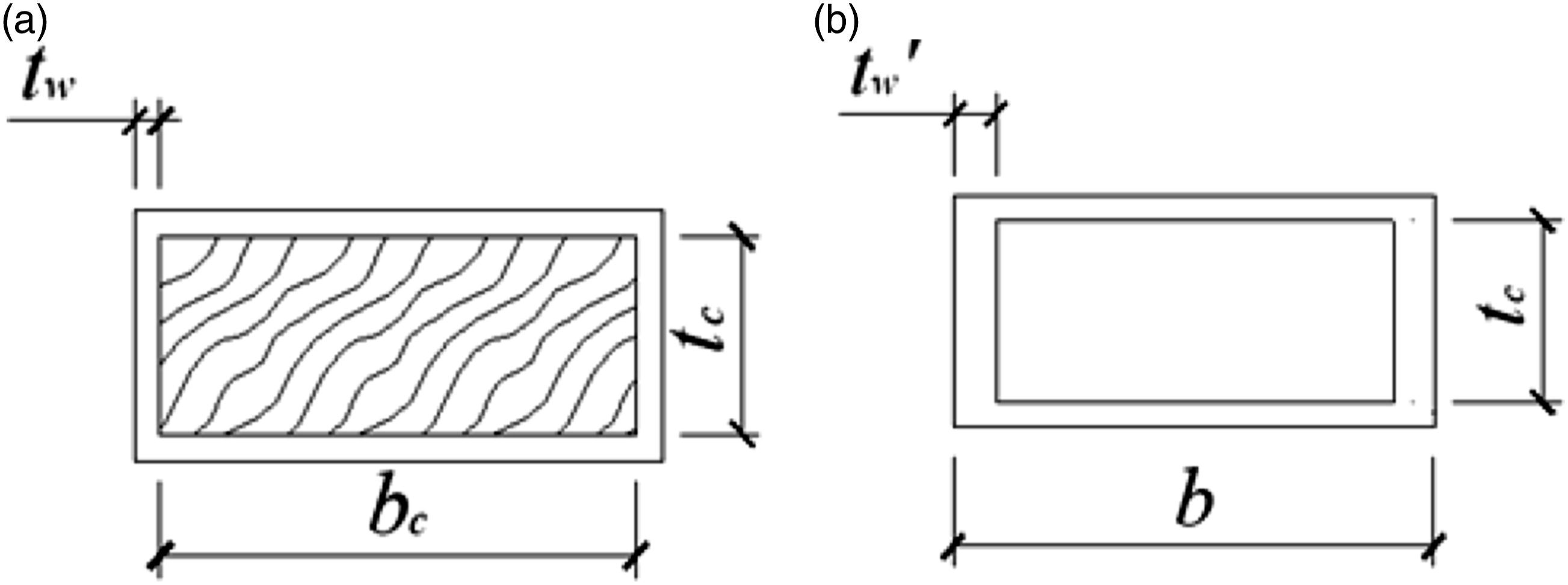
According to the principle of the shear stiffness equivalence, the wood core material can be equivalent to a web. The section form of 1PAW is taken as the theoretical analysis model, as shown in Figure 10, which is the model comparison diagram before and after the equivalence. The parameters t
f
, t
c
and t
w
’
are the thickness of the surface layer, the height of the web and the width of the web after equivalence, respectively; G
w
is the shear modulus of the lattice-web; and b is the total width of the section. Therefore, the equivalent shear stiffness is Equivalent models of 1PAW: (a) pre-equivalent model and (b) post-equivalent model.
Likewise, a similar equivalent method can be used for other forms of lattice-web wood core beams. According to the shear stiffness equivalence principle, the wood core material is equivalent to two sides of the lattice-web, as shown in Figure 11, where t
m
is the width of the lattice-web after equivalence, and the distanceΔ
x
is an element taken from the equivalent sandwich beam for analysis. Therefore, the equivalent shear stiffness of the sandwich layer is Initial and equivalent model: (a) pre-equivalent model and (b) post-equivalent model.

Deflection
According to first-order shear deformation theory, it is basically assumed that the composite surface layer and the wood core material are well bonded, no interface delamination failure occurs, and the strain distribution along the cross-sectional height under the bending moment is a continuous straight line, which meets the flat-section assumption. According to Timoshenko beam theory (Allen, 1969), when the thickness of the core material is large and the load p is applied to the beam, the deflection is composed of the bending deformation w
1
and the shear deformation w
2
.
Comparison between the experimental and theoretical values of the deflection.
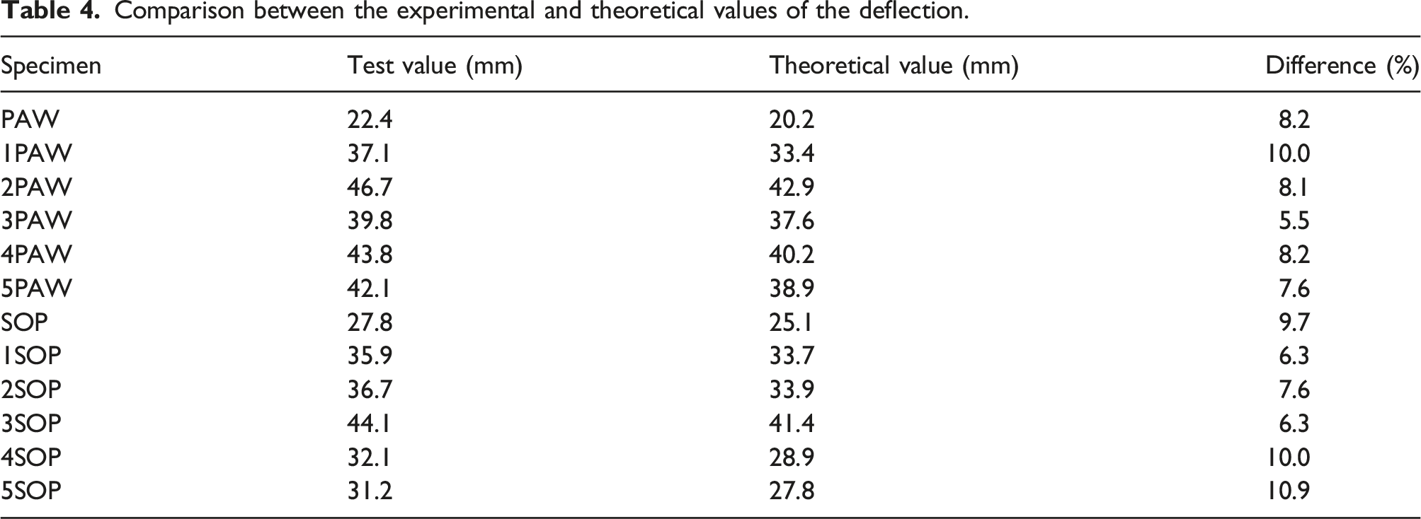
It can be seen from Table 4 that the experimental value and the theoretical value are in good agreement. Due to the defects of the test piece and other uncertain factors, the value of the mid-span deflection obtained by the test is smaller than the theoretical value, so the theoretical design value is slightly conservative.
Failure mode and ultimate bearing capacity
Under the bending load, the composite sandwich structure may have different failure modes because of the different component materials and size arrangement. The failure modes can be summarized as follows: 1) compression yield or tension fracture of the beam; 2) buckling of the compression beam; 3) shear of the core material; and 4) delamination failure. Considering that many factors may affect the shear and delamination failure of the core materials, such as different processes, interface treatment forms and resin properties, this paper focuses on the ultimate bearing capacity corresponding to the first two failure modes according to the observed failure modes.
(1) The beam is subjected to tensile fracture or compression yield critical load
(2) Buckling critical load of the compression beam

Prediction of the ultimate bearing capacity
Comparison between the theorical and experimental ultimate flexural bearing capacities.
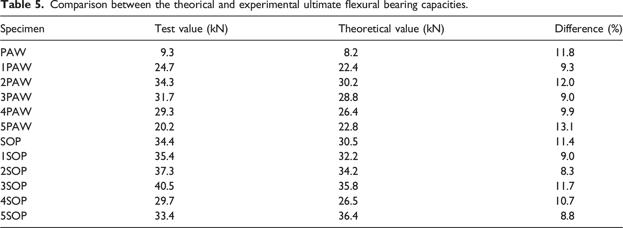
It can be seen from Table 5 that the measured values of the ultimate bearing capacity of each test piece are in good agreement with the theoretical values, indicating that the ultimate failure load of each test piece predicted by the above theoretical model is more accurate.
Influence of the lattice-web on the ductility

Displacement ductility coefficient of the PAW wood core beam.

It can be seen from Table 6 that when PAW is used as the core material, the ductility coefficient of the lattice-web wood core beam is higher than that of the wood core beam without the lattice-web. The ductility coefficient of 4PAW is the largest, reaching 1.62, and an increase in the lattice-web in the wood core beam without the lattice-web greatly improves the ductility of the specimen. When SOP is used as the core material, only the ductility coefficients of 2SOP and 5SOP are higher than those of the wood core beam without the lattice-web, and the ductility coefficient of 2SOP is the largest, reaching 1.68, but the overall improvement effect is not as obvious as that of the PAW wood core beam.
Conclusion
In this paper, focusing on the flexural behaviour of composite sandwich beams strengthened by a lattice-web, the number of lattice-webs and the type of core material are selected as the variable parameters. According to the four-point bending test, the failure modes of the structure are observed, and the theoretical analysis of its ultimate strength, stiffness and deflection is carried out. The following conclusions are drawn: (1) The strength and deflection of the SOP wood composite beam with the same section are larger than those of the PAW wood composite beam because the local compressive strength of SOP wood is greater than that of the PAW wood. The failure mode is that the upper face sheet of the beam is crushed first, then the core material is destroyed by extrusion, and finally the lower surface layer is broken. It can be summarized that the local compressive strength of the core material has a great impact on the failure mechanism. (2) The ultimate bearing capacity of 2PAW, 3PAW, 4PAW and 5PAW is 39.49%, 28.71%, 19.15% and −18.30% higher than that of 1PAW, respectively. The result shows that the optimal lattice number is 2 because the ultimate bearing capacity of 2PAW has the highest percentage improvement compared to 1PAW. While the ultimate bearing capacity of 2SOP, 3SOP, 4SOP and 5SOP is 7.43%, 14.58%, −16.10% and −5.65% higher than that of 1SOP, respectively. In the same way, the result indicates that the optimal lattice number is 3. Therefore, for different core materials, the optimal lattice number is different. The wood core composite beam with the largest number of lattice-webs does not have the optimal bending performance. Based on the comprehensive test curve and calculation result analysis, 3PAW has the largest rigidity in the PAW wood specimens and 2PAW has the largest ultimate bearing capacity; 2SOP has the largest rigidity in the Southern pine specimens and the maximum ultimate bearing capacity is 3SOP. None of them demonstrates the maximum lattice-web number of the corresponding core material.
Footnotes
Declaration of conflicting interests
The author(s) declared no potential conflicts of interest with respect to the research, authorship, and/or publication of this article.
Funding
The author(s) disclosed receipt of the following financial support for the research, authorship, and/or publication of this article: This work was supported by the National Natural Science Foundation of China (Grant No. 52078248), the Natural Science Foundation for Distinguished Young Scholars of Jiangsu Province (Grant No. BK20190034) and the Funds for Youth Creative Research Groups of Nanjing Tech University.
Data availability statement
The data used to support the findings of this study are available from the corresponding author upon request.
