
Abstract
In this paper, a new honeycomb plate box-type hollow roof structure is prepared. The failure mode and mechanical properties of the box-type hollow roof structure were analyzed by bearing capacity test and numerical analysis. The validity of the numerical analysis model is verified by comparing the results of bearing capacity test with the results of the complete coordinated model and the coupled model analysis. The results show that the failure mode of the specimen is tensile failure of the surface plate of the honeycomb plate with strengthened frame and buckling instability of the plate near the joint. The box-type hollow roof structure has good ductility. The results of static analysis and nonlinear buckling analysis of the honeycomb plate box-type hollow roof structure are carried out by coupling model are more consistent with the results of bearing capacity test.
Introduction
Aluminum alloy is widely used in spatial structure (Sugizaki et al., 1996; Yang et al., 2013) due to its low density, good corrosion resistance, easy processing, high specific strength and easy forming. Guo et al. (2015a, 2015b, 2018) conducted a detailed analysis of the semi-rigidity of aluminium alloy gusset joints, and proposed a semi-rigid model for the gusset joints. Xiong et al. (2017a, 2017b) studied the stability of single-layer reticulated shells with aluminium alloy gusset joints through experiments and numerical simulations. Wang et al. (2021a, 2021b, 2021c) studied on the mechanical property of FGC joints for single-layer aluminium alloy lattice shell structures, and proposed the design method of FGC joints through experiments, numerical analysis and theoretical analysis. Zhao et al. (2021, 2022) studied the mechanical properties of a novel modular joint of single-layer aluminium alloy lattice shell and proposed a simplified calculation formula for their ultimate bearing capacity. Zhang et al. (2021, 2022) studied the structural performance of traditional aluminium alloy Temcor (TAAT) joints and novel Box-I section hybrid gusset (ABI) joints connected by swage-locking pins. The results showed that the novel Box-I section hybrid gusset (ABI) joints connected by swage-locking pins has good potential for application in aluminium alloy spatial reticulated structures. Liu et al. (2017, 2019) studied the stability of aluminum alloy single-layer reticulated shells and flexural behavior of double-and single-layer aluminum alloy gusset-type joints, and derived the approximate calculation formula of stability safety factor and stability bearing capacity of aluminum alloy single-layer reticulated shells. The results also provide references for the design of double-layer gusset-type joints. Nastri et al. (2020, 2021a, 2021b) studied the model of aluminium alloy gusset joints and beams for single layer lattices domes verified accuracy of the component method for the modelling of joints in aluminium alloy latticed through experiments and numerical simulation analysis.
Honeycomb plate is a bionic structure (Chen et al., 2014, 2016; Mogilski et al., 2020; Zhang et al., 2016), which consists of two layers of aluminum alloy plate and aluminum honeycomb core. It has the advantages of light weight, large stiffness, sound insulation, heat insulation and fire resistance. Zhao et al. (2017a, 2017b) first proposed to a new type of aluminum alloy single-layer latticed shell with honeycomb plate. Lots of tests and numerical simulation showed that the stiffness of the aluminum alloy single-layer latticed shell with honeycomb plate is significantly better than that of the traditional aluminum alloy single-layer latticed shell. However, there are few studies on honeycomb plate used in hollow roof structure. Zhao et al. (2014, 2016a, 2016b, 2019) studied on the load capacity of new fabricated honeycomb panel open-web roof structures, the results show that the honeycomb plate hollow roof structure has a high bearing capacity, reflecting the structural characteristics of light weight and high strength.
In this paper, a honeycomb plate box-type hollow roof structure was designed and manufactured, and the bearing capacity test was carried out to study the mechanical properties and failure mode of the box-type hollow roof structure. In order to ensure the good connection performance of the structure, a set of convenient installation and reusable connectors are also designed. The static analysis and nonlinear buckling analysis of the structure are carried out by complete coordinated model and coupling model respectively. The validity of the numerical analysis model is verified by the experimental results.
Design and fabrication
Specimen design
The box-type hollow roof specimen with plane size of 1500 mm × 4898 mm, span of 4898 mm, and rise of 1680 mm. A total of 44 aluminum alloy honeycomb plates are assembled by connectors. The connectors are made of Q345 steel, and the thickness of honeycomb plates is 10 mm. The thickness of plate is 1 mm, and the thickness of core is 8 mm. The side length of hexagonal honeycomb core is 6 mm, and the wall thickness is 0.05 mm. There are three specifications of aluminum alloy honeycomb plate, namely A-type, B-type, C-type plate. The box-type hollow roof specimen and details of honeycomb plates as shown in Figure 1. The box-type hollow roof specimen and details of honeycomb plates. (a) Three - dimensional model of specimen; (b) Elevation drawing; (c) Plane drawing; (e) A-Type plate (top plate); (f) B-Type plate (Transverse side plate); (g) C-Type plate (Longitudinal side plate); (h) Details of strengthened border and honeycomb plate.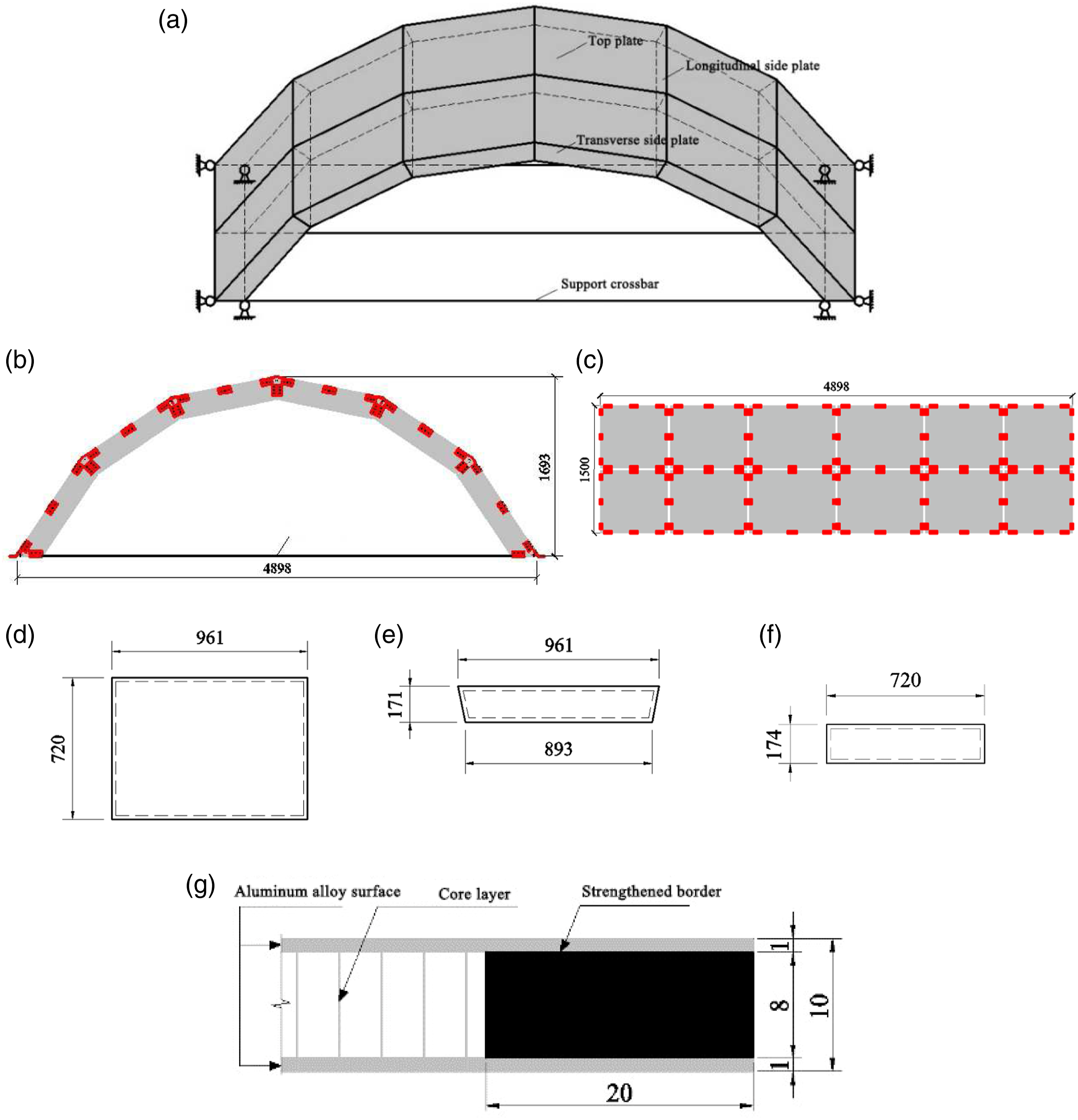
In order to ensure the common working performance of box-type hollow roof specimen, a set of connectors with fast processing, convenient installation and reusable were designed. Connectors are divided into L-type (right angle), V(small)-type (sharp angle), V(large)-type (blunt angle) and flat-type (flat angle) according to the bending angle of steel plate. The basic element of the box-type hollow roof specimen is a pentahedral box element. The connectors, element and the connection between the plates are shown in Figure 2. The connectors, element and the connection between the plates. (a) L-type connector; (b) V(small)-type connector; (c) V(large)-type connector; (d) Flat-type connector; (e) Pentahedral box unit; (f) Connection between honeycomb plates.
Support design
The box-type hollow roof specimen is supported by a fixed support. In order to solve the horizontal thrust of the arch structure, the horizontal thrust of the arch structure, a self-balancing tie rod is designed between the two supports. The strength and stiffness of the tie rod are in line with the steel structure standard (GB 50017: 2017). The design of steel plate support is shown in Figure 3. Base connection schematic. (a) Layout of steel plate base; (b) Local detail of base; (c) Local detail of base; (d) Three-dimensional graph of steel plate support.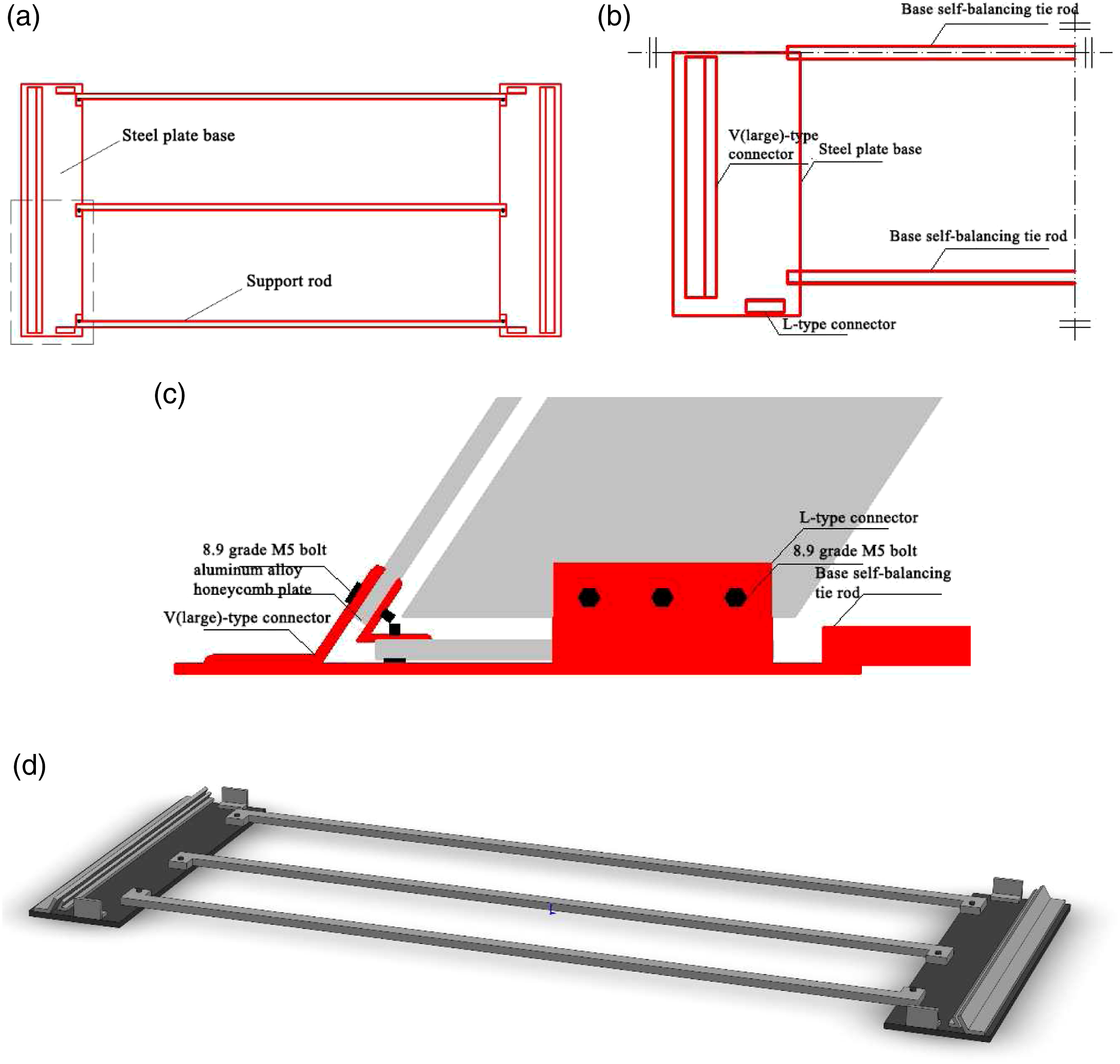
Measuring point arrangement
A total of 30 strain gauges, 36 groups of strain flowers, 12 displacement meters and a force sensor were arranged in the test. The arrangement of strain and displacement measuring points is shown in Figure 4. The arrangement of strain and displacement measuring points. (a) The layout diagram of strain measuring points; (b) The layout diagram of displacement meter.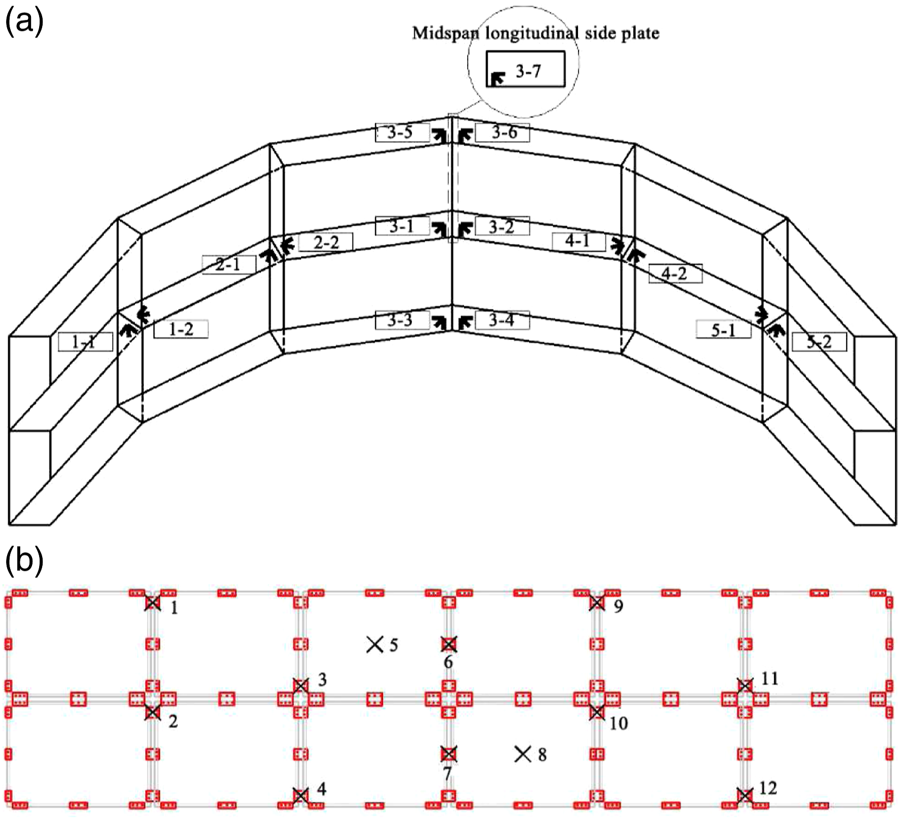
Loading method
In this paper, the hydraulic jack is used to impose two concentrated loads on the box-type hollow roof specimen through the distribution beam. The V-shaped cushion block is welded below the distribution beam, and the cushion block is placed on the V(large)-type (blunt angle) connector at the top of the specimen, as shown in Figure 5(c). Indirect force transmission is carried between the pad and the connector through two 4.8 grade screw rod, as shown in Figure 5(d). Loading method of the box-type hollow roof specimen. (a) Three-dimensional graph of test loading; (b) Loading diagram; (c) Local details of distribution beam; (d) 1-1 section.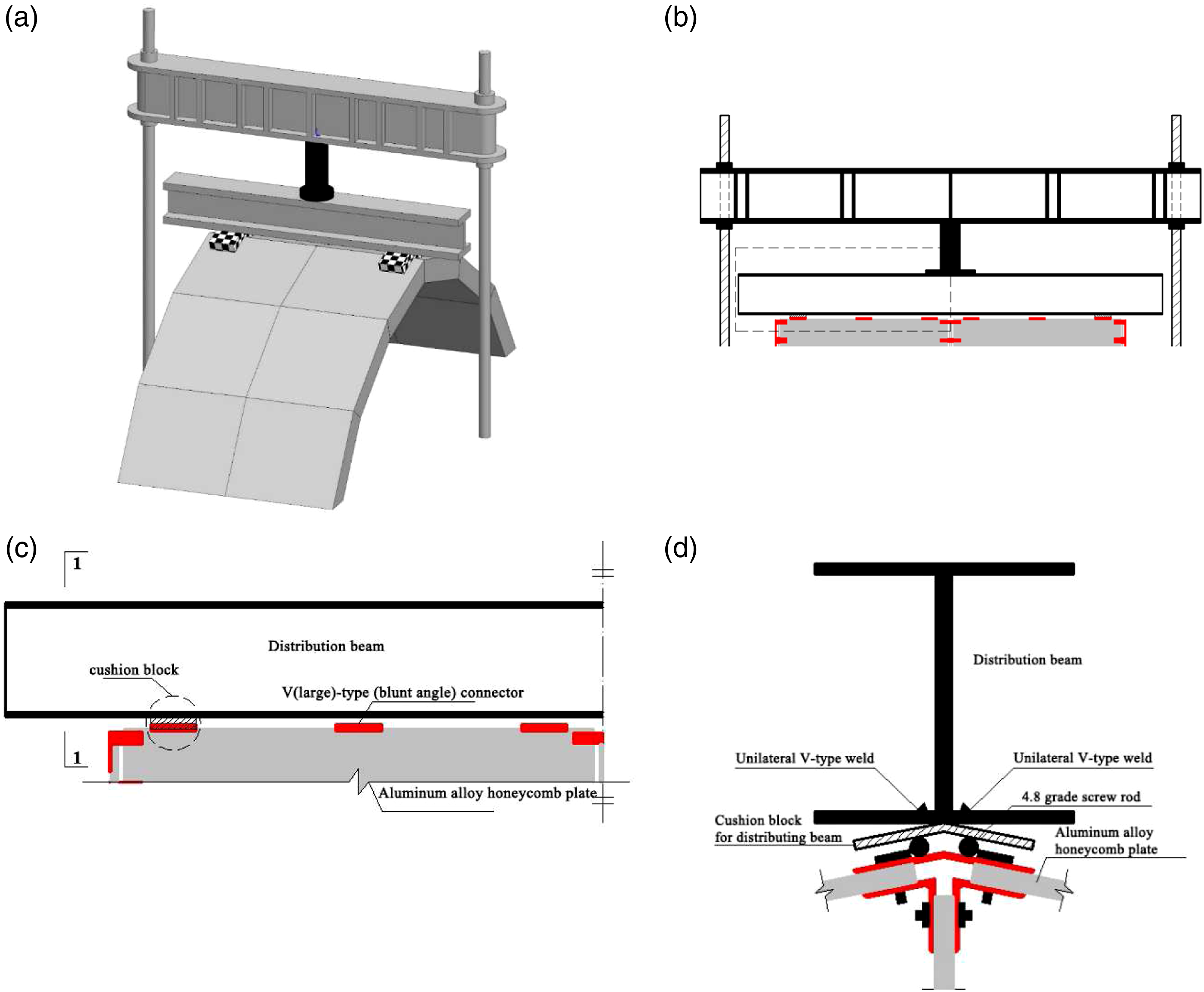
Fabrication
Aluminum alloy honeycomb plate for test has built-in reinforcing frame in production. The honeycomb plate and connectors need to be drilled before the installation of the hollow roof specimen. The connector was cut by the steel plate and bended after positioning the opening. Due to the limitation of the width of the honeycomb plate strengthening frame, the opening of the specimen should not be too large, so the 8.8 grade M5 bolt was selected for the specimen. Due to the spatial cylindrical surface of the test model, the structure needs to be assembled in horizontal position for the convenience of specimen assembly. The process of manufacturing the hollow roof specimen is shown in Figure 6. The process of manufacturing the box-type hollow roof specimen(a) Installation of connectors; (b) Connection of plate; (c) Mesh forming; (d) Installation of roof; (e) Assembly forming of the box-type hollow roof specimen.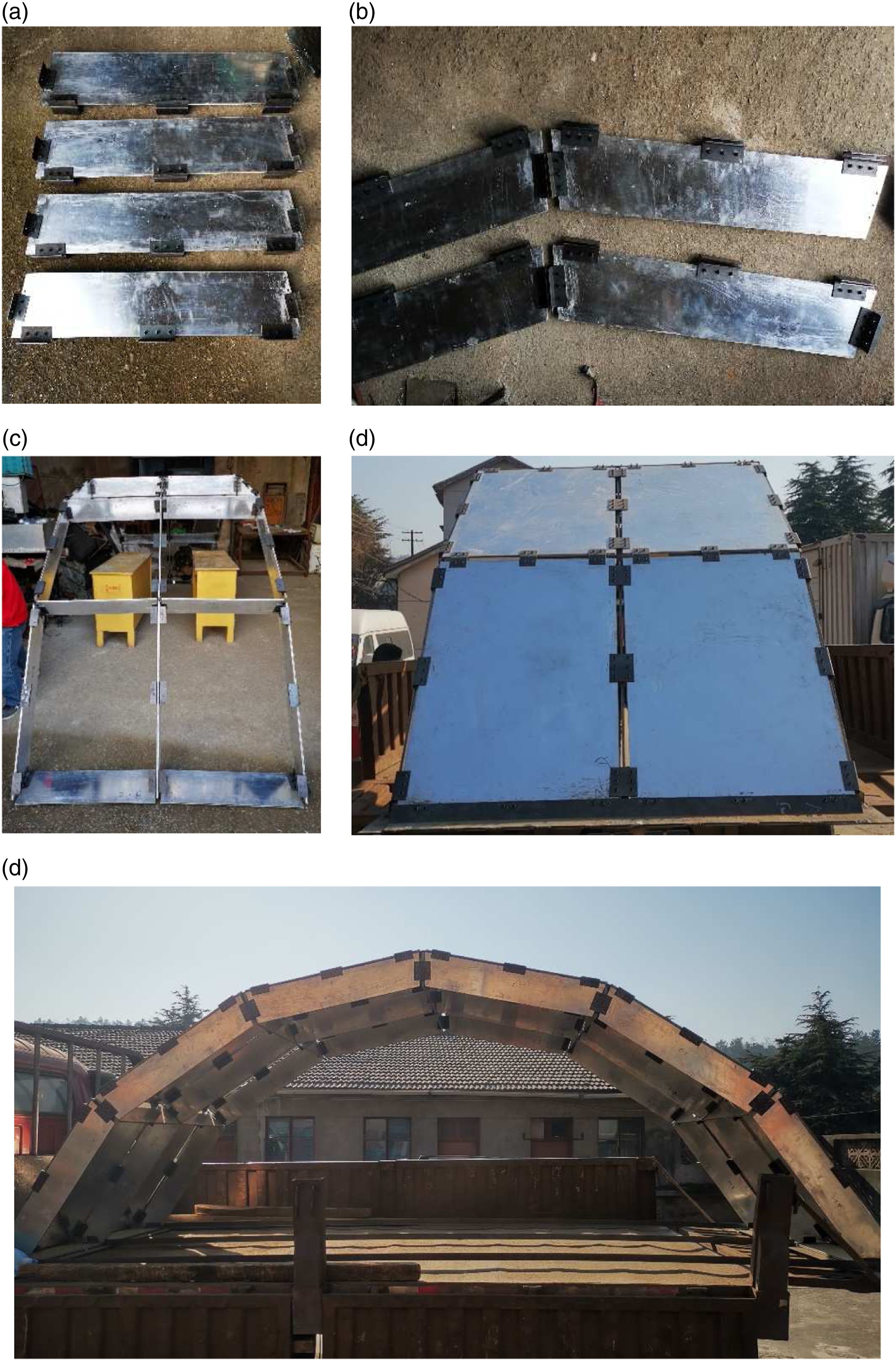
Experiments
Mechanical properties of aluminum alloy honeycomb plate
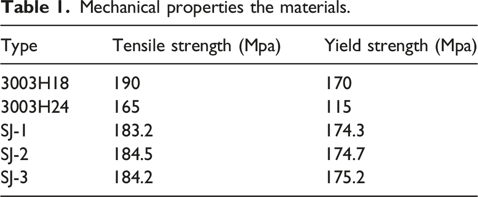
The upper and lower plates of honeycomb plate are made of 3003H24 aluminum, the honeycomb core layer is the aluminum of 3003H18, and the strengthening frame is 20# hot rolled steel. Among them, the aluminum alloy of 3003 series is Al-Mn alloy with high strength and good forming ability, which is mostly used as building materials, chemical containers or mechanical parts. The mechanical property tests of the core materials were performed based on the recommendations of GB/T 228.1-2010 and GB/T 31930-2015. Three specimens were recorded as SJ-1, SJ-2 and SJ-3, respectively. The dimensions of the specimen are shown in Figure 7. The dimensions of the specimen. (a) Physical map of specimen; (b) Size of specimen.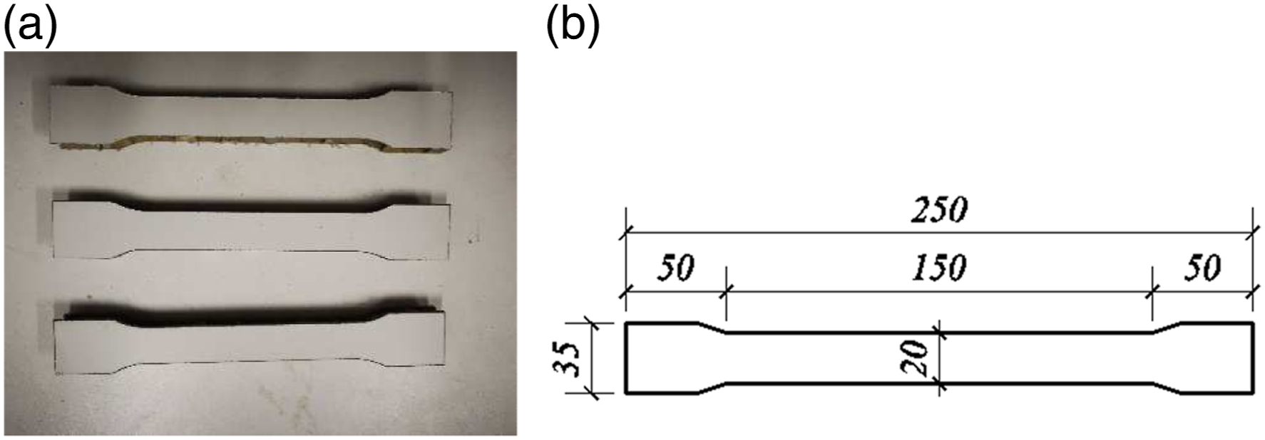
Mechanical properties the materials.
Bearing capacity test
The positive loading method was adopted in the bearing capacity test. Considering the stability and safety of the test loading, the suspension device was assembled on the site to hoist the jack, and the loading device is shown in Figure 8(a). When measuring points are arranged for the structure, it is difficult to directly arrange the displacement meter bearings, considering that the box-type hollow roof specimen is spatially curved and the measuring points fall on the inner side of the structure, and it is easy to bump and insecurity when loading. Based on this situation, the displacement meter was arranged by inverted lifting method, and the specific instrument layout is shown in Figure 8(b). After the preparation phase of the test is completed, the overall arrangement of the specimen is shown in Figure 8(c). Hollow roof specimen overall overview. (a) Loading equipment; (b) The layout diagram of displacement meter; (c) Overall profile of specimen.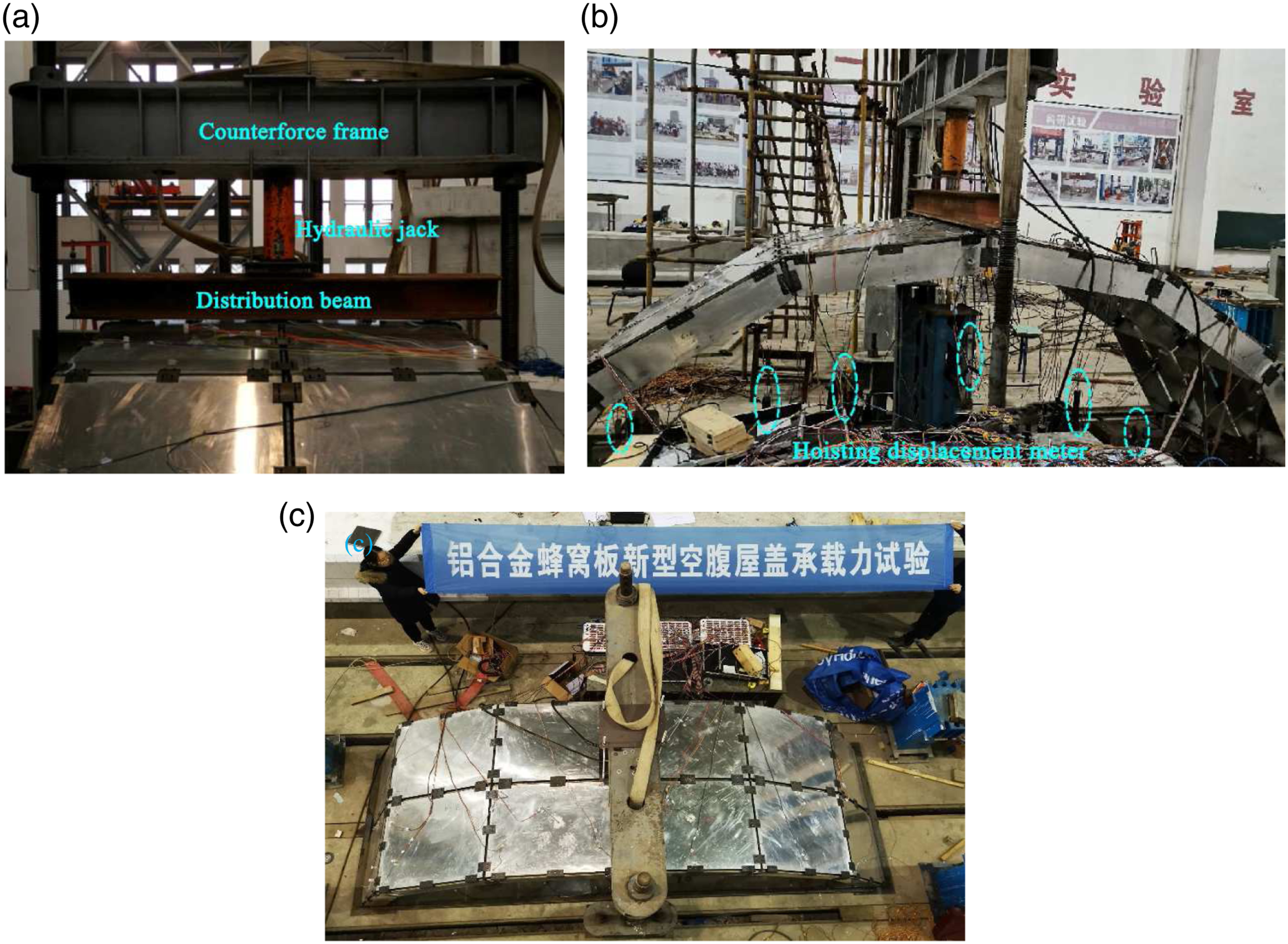
Results and discussion
Experimental result analysis
Before the formal loading, the specimen was pre-loaded three times, and the loading value was 40% of the standard load. After three pre-loadings, the load-displacement curve of the mid-span of specimen tended to be stable, as shown in Figure 10(c), and then it began to be formally loaded.
In the formal loading stage, the joints of midspan moved downward and the joints of side span arched upward. When the joint of side span was loaded to 11 kN–13 kN, the displacement value of measuring point 12 fluctuated greatly, and then remained unchanged from 14.3 kN, which means that the components near the measuring point exit from work. Similarly, local failure occurred at 14.2 kN, 19.1 kN and 25.4 kN, respectively, resulting in no change in the measured data. The load-displacement curves of failure measuring point are shown in Figure 9. Load-displacement curve of failure measuring point. (a) Measuring point 1; (b) Measuring point 2; (c) Measuring point 11; (d) Measuring point 12.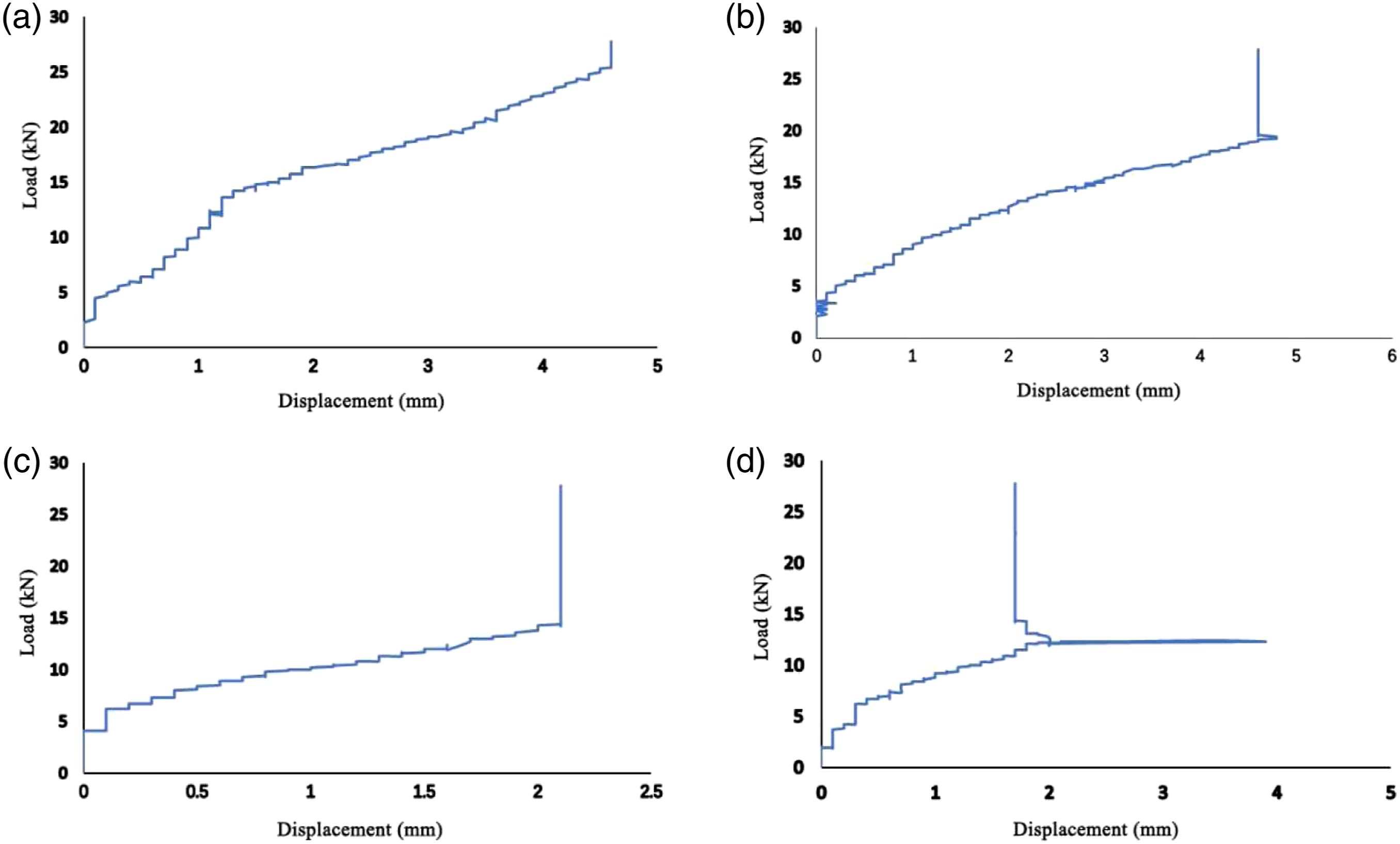
The load-displacement curves of two symmetrical measuring points 5 and 8 Figure 10(a) basically coincide in the elastic stage, indicating that the symmetrical loading of the distributive beam basically meets the requirements of the experimental design. The load-displacement curves at the left and right 1/3 spans Figure 10(b) show an increasing trend, there is an inflection point at the load of 9 kN, and then it has been rising until the failure load is reached. The inflection point is caused by the tensile failure of the plate and the buckling instability of the local honeycomb plate. When the load reaches 27.8 kN, the whole structure is damaged, and the displacement at mid-span is 31.7 mm, which show that the structure has good ductility. The displacements of the left and right 1/6 spans of the structure at 18 kN and 15 kN are no longer increased with the change of load, indicating that the honeycomb plate near the joint appears local buckling. Load-displacement curves in formal loading stage and pre-loading stage. (a) Measurement points of mid-span honeycomb plate in formal loading stage; (b) Span direction measuring points in formal loading stage; (c) Load-displacement curve of the mid-span of specimen in pre-loading stage.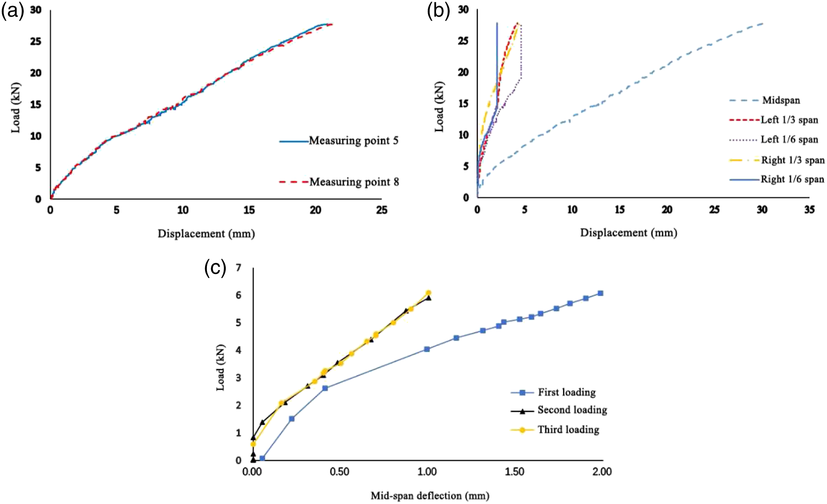
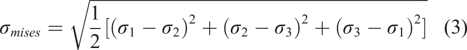
According to the measured values of strain εa, εb and εc in three directions of strain flower on the measuring point, the principal stress of the measuring point can be calculated by Formulas (1) and (2), and then the mises stress of the measuring point can be obtained according to Formulas (3) of the fourth strength theory.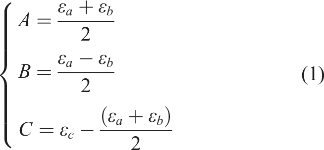

The load-stress curves (Figure 11) were drawn according to the symmetry of the measuring points for the main stress positions in the experiment. Among them, the stress value of Figure 11(d) curve is the average value of the measuring points on both sides of the joint. Load-stress curve of hollow roof structure. (a) Measuring points of middle span outside; (b) Measuring points of middle span inside; (c) Mid-span measuring point; (d) Measuring points along span direction.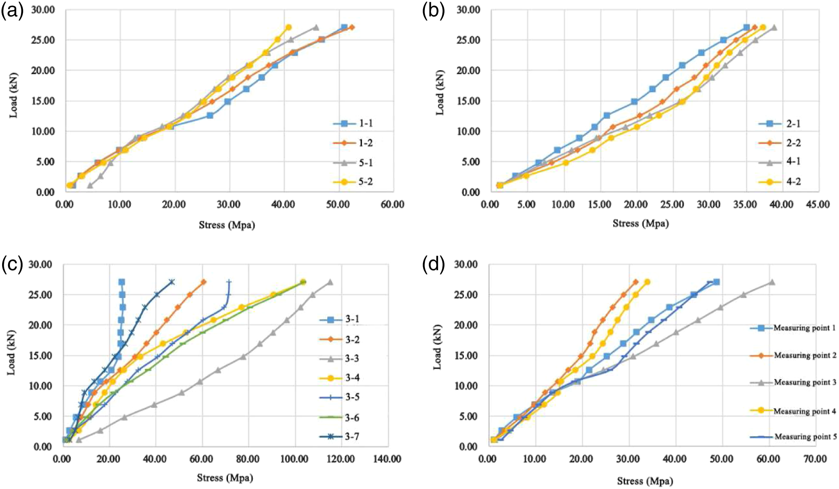
It can be seen from Figure 11(a), (b) and (d) that the structure is mainly loaded in the span direction. The stress in the middle part of the structure is the largest, followed by 1/6 span joints on both sides, and the stress value of 1/3 joints on both sides is the smallest. In addition, the force of the mid-span connection joint of the structure is obvious, and the mid-span bearing capacity of the front and rear side plates is greater than that of the middle plate. Figure 11(c) shows that the stress growth rate of the measuring point 3-3 of the lateral plate of the structure is obviously faster than that of the plates, indicating that the stress concentration phenomenon occurs at the loading point, which is caused by the loading asymmetry or installation deviation. The stress of the measuring points 3-1 of the mid-span of middle plate and 3–5 of the outer plate no longer increases with the load at 15 kN and 23 kN, respectively, indicating that the honeycomb plate is separated from the specimen, which is also consistent with the final failure of the specimen (Figure 12). Local tensile failure of honeycomb plate. (a) Tensile failure of measuring point 3-1 plate; (b) Tensile failure of measuring point 3–5 plate.
Finite element analysis of box-type hollow roof
Equivalent methods of honeycomb plate
In the finite element analysis of the overall structure, if the honeycomb plates and connectors of the structure are completely calculated by the refined model, although the accuracy of calculation results can be improved in theory, it may lead to huge calculation workload and high time cost, and even the calculation cannot converge. In this paper, the models of honeycomb plates were compared and optimized to improve the computational efficiency of finite element simulation on the basis of ensuring the accuracy of calculation results.
Firstly, the refined model of single aluminum alloy honeycomb plate was established, and then the static and dynamic performance of the single aluminum alloy honeycomb plate was compared with the three commonly used honeycomb plate equivalent theories (sandwich equivalent theory, honeycomb plate equivalent theory, equivalent plate theory) and the theoretical solution obtained by elastic mechanics, and then the appropriate aluminum alloy honeycomb plate equivalent method was selected by considering the accuracy and efficiency of calculation.
The thickness of single honeycomb plates is 10 mm, the thickness of plate is 1 mm, and the thickness of core layer is 8 mm. The Young’s modulus of aluminum alloy is 70 Gpa, shear modulus is 27 Gpa, nominal yield strength is 110 Mpa, density is 2680 kg/m3, and Poisson’s ratio is 0.3. The size of single honeycomb plate is 0.3 m × 0.3 m, the uniform load on honeycomb plate is 2 kN/m2, and the concentrated load applied to the center of honeycomb plate is 1 kN.
The plate of the refined model is solid element (Soild186), and the honeycomb core layer is shell element (Shell181). The contact pair is set between the honeycomb core and the plate. The target cell (Target170) is set on the contact node of the upper and lower plates, and the contact cell (Contact175) is set on the contact node of the honeycomb core layer. The contact method is the multi-point constraint method (MPC method), and the contact surface behavior is set to binding. The solid elements of the plate are divided into 60 parts along the height direction and along the length and width direction, and the honeycomb core layer is divided equally along the height and length direction, with a total of 18852 elements (Figure 13(a) and (b)). Equivalent methods of honeycomb plate. (a) Division of element of refined model; (b) Setting of contact of refined model; (c) Honeycomb plate before equivalence of sandwich equivalent theory (d) Honeycomb plate after equivalence of sandwich equivalent theory; (e) Honeycomb plate before equivalence of honeycomb plate equivalent theory; (f) Honeycomb plate after equivalence of honeycomb plate equivalent theory; (g) Honeycomb plate before equivalence of equivalent plate theory; (h) Honeycomb plate after equivalence of equivalent plate theory.
The sandwich equivalent theory assumes that the honeycomb core has strong transverse shear resistance and in-plane stiffness, and the honeycomb core layer is equivalent to an orthotropic homogeneous layer with the same thickness as the original core layer, as shown inFigure 13(c) and (d). For the outer skin, it is considered that it can only be subjected to in-plane force, which is subject to Kirchhoff-Love assumption. The honeycomb plate is modeled by shell181 element in ANSYS after equivalence.
The honeycomb plate equivalent theory is based on the in-plane and out-of-plane mechanical properties of the upper and lower plates and the honeycomb core layer, and the whole honeycomb plate is equivalent to an orthotropic homogeneous plate with the same thickness and equal stiffness. The equivalent process is shown in Figure 13(e) and (f).
The equivalent plate theory based on the Hoff theory, and the honeycomb plate is equivalent to an isotropic plate with equal stiffness. The equivalent plate shell is not equal to the original plate, and it can withstand the load from inside and outside the plane like the ordinary thin plate. The equivalent process is shown in Figure 13(g) and (h). Since the Shell181 element is suitable for simulating thin to medium-thick shells, the equivalent plate theory is also modeled by this element.
The results of static analysis of the single aluminum alloy honeycomb plate.

The results of dynamic analysis of the single aluminum alloy honeycomb plate.
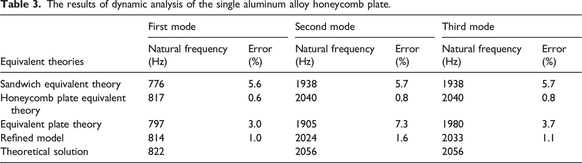
It can be seen from Tables 2 and 3 that among all the results of model, the calculation results of the fine model are the best fitted with the theoretical solution, with the optimal accuracy, but the cost of calculation is also the highest. With the increase of size of honeycomb plate and connector, the number of contact elements will increase rapidly, and the analysis time will increase geometrically. However, the three equivalent theories have the advantages of simplified modeling, low calculation cost and equivalent calculation accuracy.
In the three equivalent theoretical theories, the static and dynamic analysis results of the honeycomb plate equivalent theory can be well fitted with the theoretical solution: in the static analysis, the deflection error is controlled within 7%, while in the dynamic analysis, the error of the natural frequency is controlled within 2%, and the equivalent thickness of the model is equal to the original honeycomb plate.
The sandwich equivalent theory fails to consider the lateral shear resistance of upper and lower plates, and fails to reflect the overall performance when the upper and lower plates and the core layer work together, so it shows overall flexibility in the finite element results. Especially when the honeycomb plate is subjected to concentrated load, the Kirchhoff-Love assumption of the sandwich equivalent theory is not applicable, resulting in a large difference between the results of the sandwich equivalent theory and the theoretical solution.
Considering the three equivalent theories, the honeycomb plate equivalent theory has good accuracy in the static and dynamic analysis of single honeycomb plate. Although the equivalent parameters of the honeycomb plate model are complicated to calculate, they can be well solved by computer programming.
The numerical model of box-type hollow roof
The box-type hollow roof model is a single-core cylindrical reticulated shell structure with span of 4.9 m, rise height of 1.68 m, longitudinal length of 1.5 m, structural thickness of 0.2 m and rise span of 1/3. The finite element software ANSYS18.0 was used for modeling and analysis. The aluminum alloy honeycomb plate was simulated by Shell 181 element based on the honeycomb plate equivalent theory. The specimens were calculated and analyzed by plate-plate complete coordination model and plate-reinforced frame-connector coupling model. The plate-plate complete coordination model is an ideal model, which ignores the size of the connector and considers that the internal force and displacement of the adjacent plates are completely coordinated at the position of the connector. The calculation of this model is simple and fast, but it cannot fully reflect the cooperative working state between components, and there may be a problem of poor accuracy. In the finite element coupling model, considering that the connection parts of the edge strengthening layer of the honeycomb plate and the connector are kept intact in the test, and no buckling deformation or yield failure occurs, the connector and the strengthening frame are set to be rigidly connected. For strengthening the connection between the frame and the honeycomb plate, it is considered that their spatial translation and rotation in the plane are coordinated. Shell 181 element is also used for modeling, and the degree of freedom coupling is carried out at the connection.
Static analysis of box-type hollow roof
Complete coordination model and coupling model were used to model and analyze the specimens. The loading condition is symmetrically loaded at two points of mid-span, and the loading value is 18 kN (2.5 kN/m2). Considering the self-weight of the structure, the support condition is the fixed hinge support on both sides of the longitudinal side. Two models and results of static analysis are shown in Figure 14. Two models and their static analysis results. (a) Complete coordination model; (b) Coupling model; (c) Vertical displacement of complete coordination model; (d) Vertical displacement of coupling model; (e) Stress distribution of complete coordination model; (f) Stress distribution of coupling model; (g) Load-displacement curve of midspan; (h) Load-stress curve of midspan.
It can be found from the displacement diagram that the vertical displacement distribution of the two models is similar. The deformation of the two models is mainly symmetrically distributed along the span direction, showing the characteristics of concave middle joints and convex joints on both sides. The maximum vertical displacement of the structure occurs at the loading position (the part of blue), and the maximum vertical displacement is symmetrically distributed in the mid-span. The maximum displacements of the two models are 6 mm and 9 mm respectively. The displacement diagram of the coupled model is more accurate, which is mainly manifested in the obvious difference between the displacement of the coupled model at the plate coupling and that of the complete coordination model, especially in the shape of the funnel at the middle span. The minimum displacement at 1/6 span is related to the shape of the structure.
Comparing the stress distribution of the two models, it can be found that the stress distribution of the two models is also similar, but the stress concentration of the local joints of the coupled model is more detailed. The stress at the boundary of the middle span of the coupling model is more obvious, and the side plate is side plate to buckling, which corresponds to the failure mode of the experiment. The stress of the structure is also symmetrically distributed along the span direction. The stress at the mid-span joint and the upper arch joint on both sides is larger, and the maximum stress occurs at the loading position on both sides and the connection position in the midspan. The maximum stress of the two models are 23 Mpa and 32 Mpa respectively. The roof structure is mainly carried by the side plate in the span direction. The upper roof and the longitudinal side plate have relatively large stress in the mid-span connection, and their positions are basically not subjected to force.
Load-displacement curve and load-stress curve of complete coordinated model, coupled model and experiment model are shown in Figure 14(g) and (h). Since the complete coordinated model believes that the plates are completely rigid, the larger structural stiffness leads to smaller vertical displacement, and the model is too rigid compared with the test results. The coupling model takes into account the connection area between the plate and the connectors, and separates the reinforced frame and the honeycomb plate, so the model is more in line with the actual situation of the experiment, and the deformation value in the elastic stage is also closer to the measured value of the experiment. The stiffness of the coupling model is slightly larger than the test results, but it is smaller than the complete coordinated model. Due to the stress concentration in the joint of the coupling model, the growth rate of stress is slightly faster than the experiment value. The plates of the complete coordinated model are completely rigidly connected, and the stiffness and stress distribution are uniform, so the stress growth rate is slower than that of the other two. In addition, through the above comparative simulation, the deflection of the structure under the load of nearly five times the weight is 8 mm, and the deflection-span ratio is only 1/612, which still meets the deflection limit of 1/400 in the code, indicating that the structure has good deformation resistance.
Nonlinear buckling analysis of box-type hollow roof
In general, the buckling load obtained by the eigenvalue buckling analysis of the structure will overestimate the ultimate bearing capacity of the structure, because there are some unstable nonlinear problems in the actual structure, resulting in the weakening of the bearing capacity of the structure. Nonlinear problems of structures can be divided into three categories: geometric nonlinearity, material nonlinearity and state nonlinearity. In this paper, considering the geometric nonlinearity and material nonlinearity of the structure, the double nonlinear analysis of the finite element model is carried out.
For geometric nonlinear analysis, 16 mm (L/300) is taken as the initial defect according to the technical specification of aluminum alloy spatial grid structure (T/CECS 634: 2019), and the initial defect is applied to the structure by the uniform defect mode method. For the material nonlinear analysis, 175 Mpa is used as the yield strength of honeycomb plate. In addition, since the honeycomb plate equivalent theory is used to model the plate in the finite element analysis of the structure, the calculated stress is not the real stress of the honeycomb plate, but the stress borne by the skin. The numerical value needs to be converted equivalently before finite element analysis. The calculation process is as follows:

Firstly, the double nonlinear buckling analysis considering geometric nonlinearity and material nonlinearity is carried out for the two structural models, and then the displacement data of the maximum mid-span deflection joint of the structure are tracked. Finally, it is compared with the experimental measured values and the load-displacement curve of the structure is shown in Figure 15. The load-displacement curve of the structure. (a) The load-displacement curve of the maximum structural displacement joint; (b) Load-displacement curve after amplitude modulation.
It can be seen from Figure 15(a) that the finite element nonlinear analysis results of the structure are greater than the experimental values. The coupling model and the complete coordinated model entered the elastic-plastic loading stage at about 15 kN and 20 kN, respectively, which increased by about 67% and 122% compared with the experimental value of 9 kN. After the structure enters plasticity, the mid-span deflection growth rate of the finite element model is slower than the experimental value. This is because the mid-span joints of the structure are subjected to tensile failure due to stress concentration in the test, resulting in local plate buckling, and thus the structural stiffness is reduced, and the plastic behavior of the structure is rapidly developed. The ultimate bearing capacity of the coupled model is 32.1 kN, and that of the complete coordinated model is 43.5 kN, which is 15% and 56% higher than the ultimate bearing capacity of the experimental of 27.8 kN, respectively.
Although the bearing capacity of the model is higher than the measured value, the stiffness of the model is basically the same in the elastic stage of the structure. Therefore, it can be considered to keep the stiffness of the curve unchanged in the elastic stage, and multiply the stability bearing capacity and ultimate bearing capacity of the structure by the safety factors k1 and k2 to achieve the purpose of amplitude modulation. Ultimate bearing capacity of structures refers to the maximum capacity of structures to withstand external loads before complete collapse. Stability bearing capacity refers to the maximum force that can be endured from stable equilibrium to unstable equilibrium. When (k1, k2) are taken as (0.55, 0.8) and (0.6, 0.9) respectively, the load-displacement curve after amplitude modulation is plotted in Figure 15(b). It can be seen from the Figure 15(b) that the load-displacement curve envelope of the measured value after amplitude modulation can be well fitted between the curves. Therefore, although the coupling model overestimates the bearing capacity and deformation resistance of the actual structure, it can be used as the bearing capacity value of the actual structure after considering the safety factor. By comparing the test values, the safety factors of the stable bearing capacity and ultimate bearing capacity of the structure are k1 = 0.55–0.6 and k2 = 0.8–0.9, respectively.
Conclusion
In this paper, a new honeycomb plate box-type hollow roof structure is prepared. The failure modes and mechanical properties of the box-type hollow roof structure were analyzed by bearing capacity test and numerical simulation. The validity of the numerical analysis model is verified by the experimental results. The following main conclusions can be drawn: (1) The new box-type hollow roof structure assembled by aluminum alloy honeycomb plates and connectors has enough space stiffness and high bearing capacity. The deflection-span ratio at the maximum mid-span displacement of the plates during yield is only 1/800, and the failure load of the specimen is as high as 11 times of its own weight. (2) The box-type hollow roof structure has good ductility. The yield load of the structure is 9 kN, while the failure load reaches 27.8 kN. The failure load is about three times that of the yield load, and the maximum mid-span deflection increases from 6 mm to 30 mm. (3) The overall deformation of the specimen is concave at the mid-span node and convex at 1/6 span joints on both sides. The structure is mainly subjected to force along the arch direction, and the stress distribution is similar to the overall deformation. The stress of the mid-span joint and the convex joints on both sides is large. (4) The failure mode of the specimen is tensile failure of the surface plate of the honeycomb plate with strengthened frame and buckling instability of the plate near the joint. When the strength failure and buckling instability occur, the deflection-span ratio of the structure is still within 1/400 of the specification, indicating that the bearing capacity of the specimen is mainly controlled by strength and stability. (5) The load-displacement curve of the box-type hollow roof structure that the coupling model is in good agreement with the test in the elastic stage. Although the model will overestimate the bearing capacity of the structure to a certain extent, its ultimate bearing capacity is only 15% higher than the test value, which can be used as the design value of the bearing capacity of the structure after considering the safety factor.
Footnotes
Declaration of conflicting interests
The author(s) declared no potential conflicts of interest with respect to the research, authorship, and/or publication of this article.
Funding
The authors disclosed receipt of the following financial support for the research, authorship, and/or publication of this article: This research was financially supported by the Natural Science Foundation of China under grant NO. 51578136 and 51875102.