



Abstract
The results of an experimental investigation of six large scale rectangular reinforced concrete (RC) beams subject to different ratios of combined bending, shear, and torsion strengthened with externally-bonded carbon fiber reinforced polymer (CFRP) U-wraps are presented. All beams exhibited torsion-dominated behaviour. The presence of discrete CFRP U-wrap strips controlled the cracks well and the resulting torsional cracks were observed to be oriented at about 50°. Regardless of loading ratio, strengthened beams exhibited a 70% increase in torsional capacity. Before cracking, torsion to flexure ratio had a small effect on the flexural and torsional stiffness indicating that twist and deflection have a small counteracting effect on each other. Existing beam capacities were assessed using ACI 318-19 and GB 50010-2010 while CFRP strengthening was assessed based on fib Bulletin 14. Main findings are as follows: the ACI 318-19-predicted torsional capacity was conservative while GB 50010-2010 appeared to result in better capacity-prediction of unstrengthened RC beams. Even though load capacities derived from GB 50010-2010 are consistent with torsion-dominated behaviour, neither standard-based approach addresses the complete interaction of internal forces which is necessary to determine existing in situ strength for FRP strengthening applications. The fib Bulletin 14 approach to FRP strengthening for torsion was extrapolated to U-wraps and shown to overestimate the strengthening effect of the CFRP system applied. Critically, the assumed angle of inclination of torsional cracking was increased by the presence of the U-wraps, reducing the efficacy of the CFRP application.
Introduction
In many instances, reinforced concrete (RC) beams in buildings and other structures are subject to complex loading including shear, bending, and torsion. Well known analytical approaches such as the softened truss model (Hsu and Mo, 1985; Hsu, 1993; Jeng and Hsu, 2009; Teixeira and Bernardo, 2021) or modified compression field theory (Mitchell and Collins, 1974; Rahal, 2021; Vecchio and Collins, 1986) are able to account for such complex loading and provide adequate bases for the design of new construction. However, for existing structural members requiring repair or strengthening to mitigate deterioration, and/or to increase capacity, existing literature does not provide sufficient experimental data or an analytical approach to designing the strengthening measures, particularly for torsional loads. In some building retrofitting applications existing members not initially designed to resist torsion are called upon in the post-retrofit structure to do so; thus torsional strengthening demands can be substantial.
Externally bonded fiber reinforced polymer (FRP) composite systems are becoming a common strengthening method due to their outstanding effectiveness and convenience. Countless studies of RC beam strengthening with FRP composites under bending and/or shear are available in the literature and have informed various guide standards for FRP repair. Nonetheless, only fib Bulletin 14 (FIB, 2001) and NCHRP Report 655 (Zureick et al., 2010) provide guidance for torsional strengthening of RC members with FRP. Both guides are limited to members that are continuously wrapped with FRP around all sides (i.e., “fully-wrapped”). ACI 440.2R-17 (ACI 440.2R-17, 2017), on the other hand, does not consider torsion strengthening at all.
In a recent review paper, Alabdulhady and Sneed (Alabdulhady and Sneed, 2019) assembled almost all existing torsion tests of RC beams strengthened with FRP; this amounted to 84 beams reported from 16 studies. Significant torsional strength increases averaging 51% were reported across the literature. Unsurprisingly, fully-wrapped (i.e., 4-sided) FRP sections exhibited the best performance.
In practice, torsion often occurs simultaneously with shear and bending. Based on earlier investigations of strengthened RC members subject to pure torsion, a few studies have been conducted on strengthened members subject to complex loadings including torsional moment.
Hii and Al-Mahaid (Hii and Al-Mahaid, 2006) conducted an experimental and numerical investigation on strengthened solid and box-section beams subject to the same loading ratio of combined torsion shear and flexure. In this study, increases in the ultimate strengths was up to 78%, and good agreement between experimental and numerical results was found. An analytical model for fully wrapped box-section beams subject to combined bending, shear and torsion was proposed based on the modified diagonal compression field theory, and good agreement was found with test results of four specimens strengthened with different schemes but subject to the same loading ratio (Jing and Gruenberg, 2006). Deifalla and Ghobarah (Deifalla and Ghobarah, 2010) studied strengthened RC T-beams subject to combined torsion and shear. In this study four strengthening schemes were tested, and the full wrapping was the most effective schemes. The bearing capacities were increased up to 71% and the deformability was also increased. 17 strengthened RC beams were tested subject to the same loading ratio of torsion (Soluit et al., 2008), shear and flexure were studied. In this study, the bearing capacities were increased up to 163%, and the anchorage at the ends of FRP strips was found important to prevent debonding. 9 strengthened RC beams were tested subject to torsion and flexure (Mostofinejad and Talaeitaba, 2014), the bearing capacities were increased up to 116%, and The increase in the cracking and ultimate load was decreased with the load eccentricity. 8 RC beams strengthened using different schemes were tested (Ilkhani et al., 2021) subject to pure torsion and combined torsion-bending. In this study, adequate increases in capacity were also observed, and a suggestion of using the carbon fiber reinforced polymer (CFRP) sheets in the corners of beams were proposed to increase bearing capacity.
In the literature, U-wrapped tee-shaped members, fully wrapped rectangular members, and fully wrapped hollow box members subject to flexure, shear and torsion have been tested. Nonetheless, many parameters such as load ratios, beam shapes, strengthening schemes, and strengthening materials have not been investigated, and the behavior and mechanism of FRP-strengthened members subject to complex loading remains unclear. The lack of experimental and analytical studies along with the increase demand in the application of FRP composites for repair and strengthening of RC members motivate the present study.
This paper presents a study of rectangular RC beams strengthened with externally bonded CFRP composite systems subject to combined bending, shear, and torsion. Four rectangular RC beams strengthened using the same CFRP scheme and two unstrengthened control beams were tested under different ratios of flexural moment to shear (M/V), torsional moment to flexural moment (T/M), and torsional moment to shear (T/V). Observed beam capacities were assessed using available models based on existing codes and literature.
Experimental investigation
Test beams
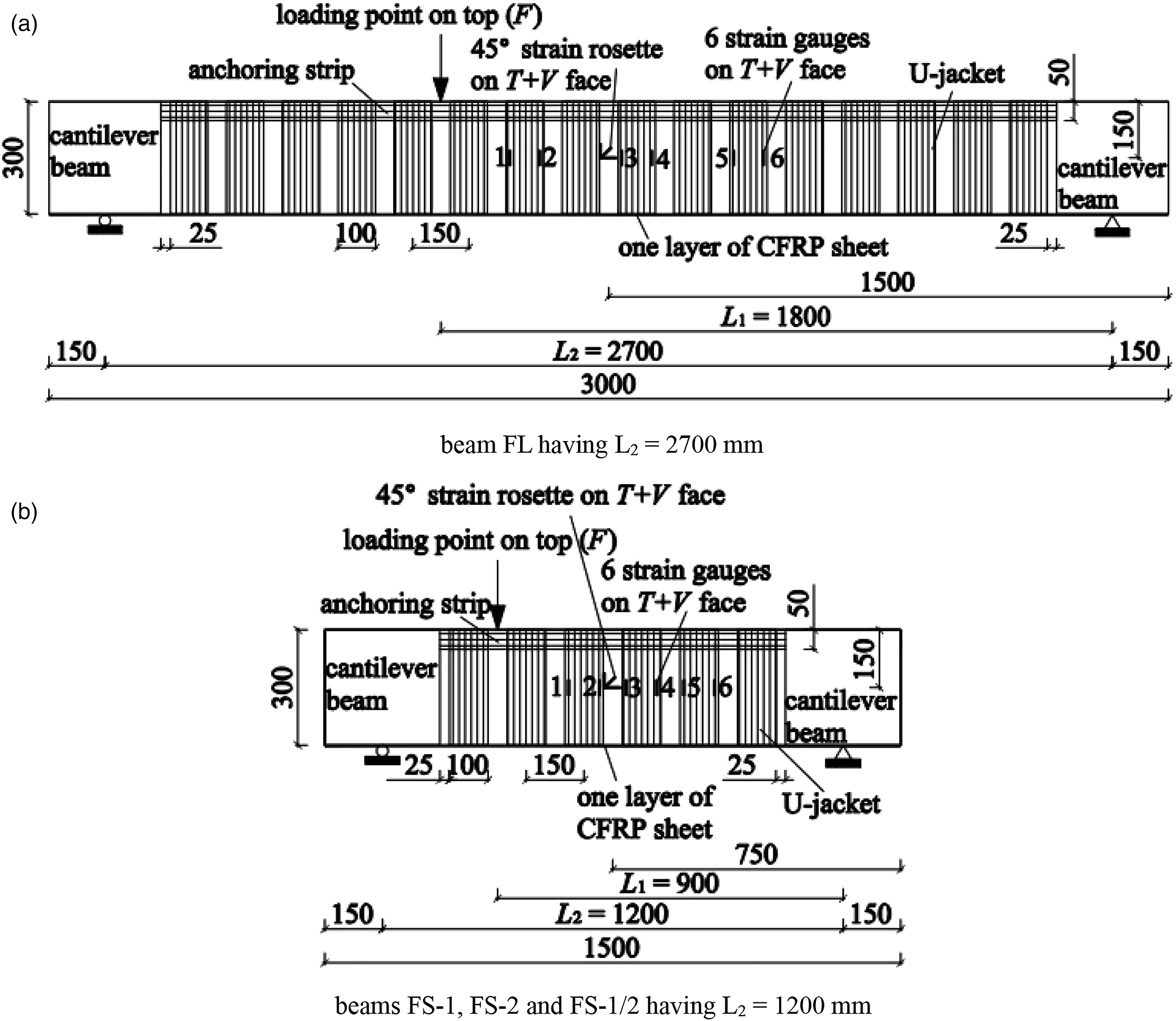
Six solid RC beams, 300 mm deep (h) and 150 mm wide (b) were prepared and tested. As shown in Figure 1(a) and 1(b), the beams are Z-shaped, having cantilever stubs at each end of a straight test region. Loading is applied as shown in Figure 1(a), with one load being applied to the test region of the beam and the other, using a distribution beam, applied to the ends of the cantilever stubs. This arrangement results in a combination of flexural moment, M, shear, V, and torsional moment, T, in the middle straight portions of the beams. To achieve different ratios of moment, shear and torsion, the dimensions L
1
to L
4
are varied from beam-to-beam as given in Table 1. Reinforcement details of each beam are shown in Figure 1(c) and 1(d). The two cantilever stubs at either end of the test region are not part of the test region and were designed to resist the maximum forces anticipated during testing; details are shown in Figure 1(e). Beams BS, FS-1, FS-2, and FS-1/2 were designed with the same shear span, L
1
= 900 mm but with different lengths of cantilever stub, L
4
. Beam BS was the unstrengthened control for this group. Beams BL and FL were unstrengthened and strengthened companion beams having L
1
= 1800 mm. Beam details. Test beam dimensions and load ratios.

The beams had two 10 mm diameter longitudinal reinforcing bars top and bottom (Figure 1) resulting in a gross section longitudinal reinforcing ratio ρ = A s /bh = 0.0070 or tension reinforcement ratio of 0.0035, where A s is the total area of longitudinal reinforcing bars. These bars had a nominal yield strength of 400 MPa and a measured tensile strength of 634 MPa (i.e., Chinese grade HRB400). The testing region, having a length L 1 – 150 mm in each beam, had 6 mm diameter closed hoop stirrups spaced at 150 mm on center (s), resulting in transverse reinforcement ratio ρ v = A v /bs = 0.0025 (Figure 1), where A v is the area of transverse reinforcement at a section. The 6 mm bars had measured yield and tensile strengths of 316 MPa and 477 MPa, respectively (i.e, Chinese grade HPB335). Beyond the test region, the transverse reinforcement ratio was increased to 0.013 using 8 mm hoops at 50 mm on center; these bars had nominal yield and measured tensile strengths of 400 MPa and 646 MPa, respectively (i.e., Chinese grade HRB400). All beams were cast with commercial ready-mix concrete having siliceous coarse aggregate. The measured 28-day cube compressive strength was f ck = 60.6 MPa.
CFRP Strengthening
Beams BS and BL were unstrengthened control beams. The remainder of beams were strengthened with externally bonded CFRP. The 300 g/m2 (dry areal weight) CFRP used had manufacturer-reported ultimate tensile strength, f fu = 3600 MPa and tensile modulus E f = 237 GPa, making the rupture strain, ε fu = 0.0152 when CFRP is bonded using epoxy resin. The CFRP was applied to the concrete using an epoxy saturating resin having manufacturer-reported tensile strength, tensile modulus and elongation of 60.3 MPa, 2721 MPa and 1.6%, respectively. The manufacturer reported CFRP-to-concrete tensile bond strength was 3.4 MPa.
The design thickness of the CFRP sheets was t
f
= 0.167 mm. The strengthening scheme, shown in Figure 2, proceeded as follows: a) One ply of 130 mm (b
f
) wide longitudinally-oriented CFRP was applied to the beam soffit as flexural strengthening. This corresponds to increasing the [equivalent steel] tension reinforcement ratio ρ
f
= (b
f
t
f
/bh)(E
f
/E
s
) = 0.0006, effectively increasing the tension reinforcement ratio 16% to 0.0041. E
s
is the elastic modulus of steel bars and taken as 200 GPa. One ply of CFRP sheet applied to the soffit was quite common for enhancing the flexural capacity of beams. b) Single-ply CFRP U-wraps, 100 mm wide (w
f
) spaced at 150 mm on center (s
f
) were placed on top of the longitudinal ply. The U-wraps extended to the top of the sides of the beams but did not extend to the top surface. Thus a 3-sided retrofit was affected. The [equivalent steel] transverse reinforcement ratio of the CFRP is ρ
vf
= (2t
f
w
f
/bs
f
)(E
f
/E
s
) = 0.00176, effectively increasing the transverse reinforcement ratio in the test region 70% to 0.00426. This strengthening scheme was quite common in practice and among other studies on strengthened beams under pure torsion. In other studies, ρ
vf
ranges between 0.0003–0.003 (Mostofinejad and Talaeitaba, 2014). To ensure a smooth transition from vertical face to soffit, the bottom corners of the beam sections were rounded to a radius of 10 mm (Soluit et al., 2008). c) Finally, the top ends of the U-wraps were anchored with a 50 mm wide longitudinally-oriented CFRP strip. Because this strip is not itself anchored, it is unlikely to contribute in a meaningful way to the flexural or torsional capacity of the beam, Details of CFRP strengthening.
Test set-up and instrumentation
Figure 1(a) shows the arrangement of the loading system. In order to exert torsional moment in the test region, the beam was loaded by applying two equal concentrated loads (F/2) at the ends of the cantilevers stubs. A second concentrated load (F), defining the shear span, was applied in the test region a distance L
1
from a support. The beam was supported on two-axis roller supports (Figure 1(b)) placed at the junction of the straight test regions and the cantilever stubs. The maximum internal forces in the test region defined by L
1
are given as:


Test results and capacity predictions.

aV req > V c /2; minimum shear reinforcement required: (A v /s) provided = 0.38 mm > (A v /s) min = 0.23 mm.
bthis value controls.
Figure 1(b) shows the arrangement of displacement transducers on the beam soffit. Δ1 and Δ3 are arranged transversely below the load point while Δ4 and Δ5 are located at the center of the shear span L
1
. The sensor pairs each have a 130 mm transverse spacing. Δ2 records the vertical deflection of the beam at the point of load application. The angle of twist per unit length resulting from torsion is calculated from the measured displacements as follows:
45° strain rosettes (3 strain gages were attached in 0°, 45°, and 90° separately) were installed at the center of the top (Figure 1(b)) and vertical (Figure 2) faces of the beams where shear stress caused by torsion and shear force were additive. Six strain gauges were installed on three different CFRP U-wraps on the additive vertical face (Figure 2) and one strain gauge was installed on the CFRP at the center of the strengthened beam soffit. All data were simultaneously recorded using a dynamic data logger.
Test results
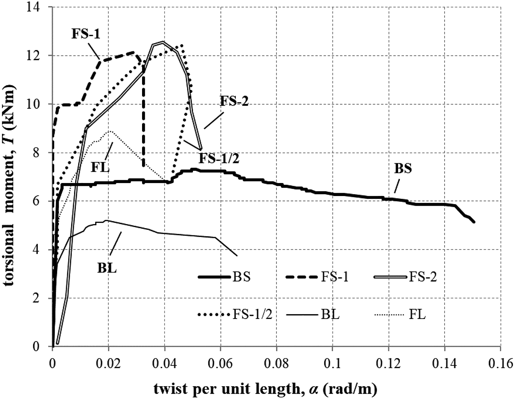
Table 2 (rows 1–10) summarizes key results at cracking and ultimate loads. The shear force, bending moment and torsional moment are determined from Equations (1) to (3). The displacement is that recorded at Δ2 and the angle of twist per unit length is determined form equation (4). The bending moment–deflection (M-Δ
2
) curves are shown in Figure 3 and the torsional moment–twist angle (T-α) curves are shown in Figure 4. Observed crack patterns of all beams at the end of testing are presented in Figures 5 and 6. Experimentally determined bending moment – deflection response. Experimentally determined torsional moment – twist response. Crack patterns and failure modes of short beams having L2 = 1200 mm. Crack patterns and failure modes of long beams having L2 = 2700 mm.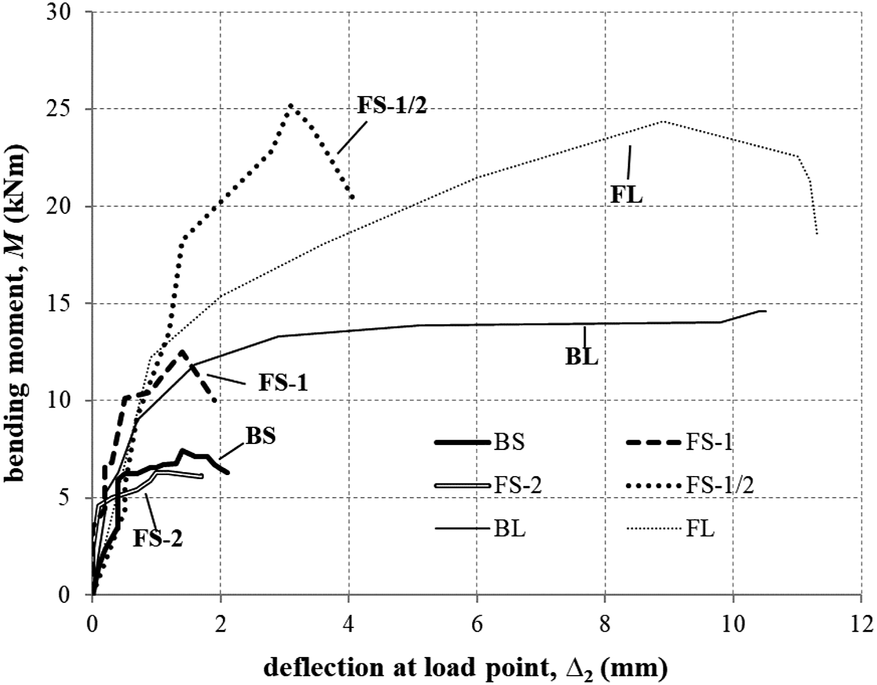


Failure modes
All beams – unstrengthened and strengthened – exhibited torsion-dominated behaviour, for control beam BS, having T/M = 1, cracking initiated on both vertical faces and on the beam soffit. A dominant spiral crack oriented at 45° to the beam longitudinal axis was observed on each vertical face followed shortly by the extension of this spiral crack to the top beam surface. Local concrete cover spalling and crushing was observed on the vertical face where the compressive effects of shear and torsion were additive (Figure 5(a)). Control beam BL, having a much lower T/M = 0.375 exhibited initial flexural cracking on both vertical faces and the soffit. Following this, 45° spiral cracks appeared on all four faces. Similar to beam BS, local concrete cover spalling and concrete crushing was observed on the critical compressive face of the beam (Figure 6(a)). As seen in Figures 3 and 4, beams BS and BL both exhibited reasonable levels of ductility although both ultimately exhibited a sudden catastrophic failure.
CFRP strengthened beams FS-1 and FL are directly comparable to BS and BL since these beams had the same T/M ratios. FS-2 and FS-1/2 had higher and lower T/M ratios than BS, respectively. For the CFRP strengthened beams, cracking and ultimate loads were increased. Additionally, the ratio of ultimate to cracking load was also greater than the unstrengthened control beams. Spiral cracking associated with torsion was distributed (rather than a single dominant crack). The resulting network of spiral cracks were oriented between 40° and 60° to the longitudinal axis of the beams (Figures 5 and 6). The orientation of the dominant cracking was defined by the CFRP strip width (w f ) and spacing (s f ) and overall height of beam (h): tan(θ) ≈ h/(w f + s f ) ≈ 50°. It was clear that the presence of the CFRP strips controlled the cracks well: inhibiting propagation and limiting crack width. All strengthened beams exhibited a similar 70% increase in torsional capacity.
In the shorter span CFRP strengthened beams (Figure 5) CFRP debonding and splitting on the vertical face were shear and torsion-induced stresses are additive was observed. Rupture of one CFRP U-wrap at the bottom corner was observed in each beam. Local concrete cover spalling and crushing was also observed on the vertical face were compression stresses are additive. Similar behaviour was observed for FL, having a lower T/M = 0.375, although no CFRP rupture was observed in this beam (Figure 6(b)).
For beams BS, FS-1, FS-1/2, and FL, the applied load exerting shear and bending, and that causing torsion, both fell at least 15% from their maximum capacities at failure. However, for beams BL and FS-2, only the load exerting torsion dropped at least 15%. This suggests that BL (being under reinforced for shear) and FS-2 (having a very high torsion load) were dominated by torsional behaviour and had not reached their flexural capacities.
Beam capacity and stiffness
The externally bonded CFRP significantly enhanced the cracking and ultimate capacity of the tested beams. As reported in Table 2, beam FS-1, which had the same load ratios as the control beam BS, exhibited increases in cracking and ultimate capacity of 50% and 66%, respectively. For beam FL, which had the same load ratios as the control beam BL, the same increases were 28% and 70%, respectively. The increase in ultimate torsional capacity was very similar for all strengthened beams: approximately 70% (Table 2 row 12).
As expected, beams having a short shear span – having both larger V/M and T/M ratios – are dominated by the additive effects of shear and torsion. Longer beams, having lower proportional shear stress exhibit a more flexure-dominated response. For strengthened beams FS-1/2, FS-1, and FS-2, each with the same shear span but having T/M varying from 0.5 to 2, the torsional responses shown in Figure 4 were quite similar. Beams FS-1/2 and FL had similar T/M ratios and failed at similar applied flexural moments. The longer (i.e., more flexure-dominant) shear span of beam FL resulted in a lower torsional moment and twist angle at failure.
As shown in Figure 3, the flexural stiffness (slopes of curves) of all beams before cracking was quite similar. However, among strengthened beams FS-1/2, FS-1, and FS-2, each with the same shear span, the flexural stiffness before cracking decreased with the decrease of torsion to flexure ratio. As shown in Figure 4, the torsional stiffness (slopes of curves) of all beams before cracking was quite similar, except for beam FS-2, which had the largest torsion to flexure ratio. The similar trend in both flexural and torsional stiffness indicating that twist and deflection have a small counteracting effect on each other. The flexural and torsional stiffness of strengthened beams was similar to the stiffness of unstrengthened beams and all dropped distinctly following cracking. This is typical of FRP-strengthening which has very little effect on gross section (uncracked) stiffness. Post cracking stiffness of both beams FS-1 and FL was greater than their respective control beams, BS and BL. The improvement in post-cracking stiffness is attributable to the improved crack control affected by the CFRP and the elimination of the single dominant 45° crack.
Concrete surface strains and cracking behavior
Figure 7 shows the angle of principal tension strain (relative to the beam longitudinal axis) before cracking calculated from the 45° strain rosettes data at the vertical and top faces of the beams. The top face strain rosettes on FS-1 failed and is not shown. As shown in Figure 7(a), the direction of the principal strain at the center of the vertical face reached 40°–45° at very low applied loads and remained essentially constant until cracking occurred. This result is expected since the strain rosettes are located at mid-depth of the beam (at the uncracked neutral axis) and are therefore subject to only pure shear. The direction of principal strain on the top face of each beam is lower than 45° due to the presence of flexure-induced compression. Indeed, the angle of principal strain is barely 25° for the longer BL and FL beams. Direction of principal tension strain determined from 45° strain rosettes.
As described above and shown in Figures 5(a) and 6(a), the unstrengthened beams BS and BL developed 45° spiral cracks. Although the pre-cracking strains were the same, the eventual cracking angle in the CFRP-strengthened beams was steeper – between about 50° and 55°. This observation confirms the crack controlling effects of the CFRP U-wraps. The U-wraps provide discrete vertical tension ties between which diagonal compression struts develop. The cracking, perpendicular to the struts, thus adopts the angle ‘enforced’ by the CFRP depth and spacing – about 50° in this study. This effect can be seen in the cracks shown between U-wraps in Figures 5 and 6. The higher flexure-induced compression delayed torsional crack development across the top face of the beams as described above.
Strain of CFRP
Strains recorded from gages on bonded U-wraps are effected primarily by the proximity of the gage to the crack path. Only gages intersected by a crack will provide an indication of the peak CFRP strains observed. Those gages away from the crack path will be relatively unaffected and record low strains. Such significant variation of observed strains in FRP shear reinforcement is well known in the literature and may be more pronounced in the presence of torsion (Hii and Al-Mahaidi, 2006). Based observed crack location (Figures 5 and 6) relative to U-wrap strain gage location (Figure 2), the most critical gages were identified and their response relative to torsional moments are plotted in Figure 8. In the beams having a short shear span, peak CFRP U-wrap strain observed was about 5600 με. Design strain for FRP reinforcement resisting shear stresses is conventionally limited to 4000 με; above this value the concrete contribution to shear resistance is believe to be degrade significantly (ACI 440.2R-17, 2017). CFRP U-wrap strain at critical gage.
Strains recorded on the longitudinally oriented CFRP are shown in Figure 9. The more pronounced flexural behaviour of beam FL is evident although for beams FS-1, FS-2 and FL, the strains remained well below the expected debonding (ACI 440.2R-17, 2017) or rupture capacity of the CFRP indicating that the flexural strengthening was not engaged to a significant degree. The rapid increase in strain to 7000 με in beam FS-1/2 likely reflects the presence of a crack opening under the gage. This would be accompanied by local debonding which would be arrested by adjacent U-wraps, allowing further strain development as seen in Figure 9. Strain in longitudinal CFRP.
Prediction of beam behaviour and strengthening demand
Capacity of FRP-strengthened members is conventionally described by the summation of the existing RC member capacity and the incremental capacity provided by the FRP (ACI 440.2R-17, 2017; FIB, 2001; Zureick et al., 2010). In this study, the RC member capacity determined based on ACI 318-19 (ACI 318-19, 2019) and Chinese GB 50010-2010 (GB 50010-2010 (2015 Edition), 2015) are adopted for comparison. In terms of incremental FRP capacity, only fib bulletin 14 (FIB, 2001) provides design equations for all four actions: axial (not considered here), flexure, shear and torsion. Nonetheless, no guidance in the interaction of these actions is provided. Modified fib approaches to determining CFRP contributions are adopted in this study (Ameli et al., 2007; Ghobarah et al., 2002; Ma et al., 2018).
Bending moment capacity of beams
In all design approaches, bending moment capacity is calculated based on the plane section assumption without considering the effects of other loads. This is shown schematically in Figure 10 in which ε
0
is the extreme tension face strain at the time of FRP application. The neutral axis depth, x, is calculated from strain compatibility and internal force equilibrium, and the bending moment capacity is determined from moment equilibrium. Equivalent concrete compression stress block factors, α
1
and β
1
and the assumed extreme concrete compression strain, ε
cu
, are summarized in Table 3 for the design standards considered in this study. Plane sections analysis for the ultimate limit state in flexure. Values of εcu, α1 and β1.

Shear and torsion capacity of reinforced concrete beams
ACI 318-19 design practice
In ACI 318-19 (ACI 318-19, 2019), shear and torsion reinforcement requirements are calculated separately and added to each other. Nominal shear capacity, V
n
, is determined as the sum of concrete and reinforcing components: V
n
= V
c
+ V
s
. The concrete component is given as:

Like shear, ACI 318-19 defines a threshold value of torsion below which no additional reinforcement is required. Since this study focuses on torsional strengthening, it is assumed that this threshold is surpassed. Thus, assuming cracked behaviour, torsion is resisted based on a space truss analogy with no contribution from the concrete (ACI 318-19, 2019) The torsional resistance T
n
is taken as the lesser of Equations (7) and (8) reflecting yield of the transverse or longitudinal reinforcement, respectively:

GB 50010-2010 design practice
In GB 50010-2010 (GB 50010-2010 (2015 Edition), 2015), the interaction of shear and torsion is considered if the shear is greater than the lower limit calculated as:


In this experiment, the shear capacity of members is below the lower limit given by equation (9), and the torsional capacity of members is calculated as pure torsion, which is consistent with torsion-dominated behaviour observed.
Existing member capacity
For new member design, the required transverse reinforcement in a member is A
v
+ A
t
, where A
v
is the same as in equation (6), and A
t
is the same as in equation (7). Similarly, the same A
L
from equation (8) is added to the reinforcement required to resist flexure. This implies a linear combination of the effects of flexure, shear and torsion is appropriate when assessing an existing member. That is, when assessing the adequacy of transverse reinforcement in an existing member in the context of ACI 318-19 (ACI 318-19, 2019):

Assuming strengthening is required, the calculation of existing capacity becomes convoluted. Because the transverse steel contributes to both shear and torsion, and the longitudinal steel to both flexure and torsion, the proportional contribution of the reinforcing steel to each action must be determined and capacities factored accordingly. Known T/V and T/M ratios (Table 1, for instance) may be used to allocate the contributions of transverse and longitudinal reinforcement, respectively.
Not accounting for interaction effects, the calculated pure flexure, pure shear and pure torsional capacities of the unstrengthened test beams BS and BL are summarized in Table 2 (rows 13–24). For both the long and short beams, the concrete component of shear resistance, V c is adequate to develop the full flexural capacity of the beam. Indeed, even in the worst case shown in Table 2, the moment demand could be doubled and the existing beams would be adequate for the resulting shear. Based on present design philosophy, this leaves 100% of the transverse reinforcement available to resist torsional loads. This assumption is not likely correct in a torsional strengthening scenario since the member will likely be cracked; therefore, engaging the transverse steel as a component of both shear and torsion resistance.
Torsional strengthening with CFRP
Considering the foregoing discussion and the ratios of T/M given in Table 1, the unstrengthened beams BS and BL are clearly torsion critical in this test program. The calculated torsional resistances are low (Table 2, rows 18 and 24). Using ACI 318-19 calculations the controlling torsion strength (Equation (7)) can be fully developed with both the shear (V s is not required) and flexure (equation (7) does not consider the longitudinal bars) although T/M is only 0.09.
fib Bulletin 14 (FIB, 2001) provides a model for calculating the FRP contribution to torsional capacity although this approach requires fully wrapped cross sections. A modified version of the fib approach is adopted here (Ameli et al., 2007) to calculate the contribution of the U-wraps provided:
ε
fe
is the strain that may be developed in the CFRP U-wrap as limited by fiber rupture (Equation (16)) or debonding (Equation (17)). ε
fe
is the lesser of:

Regardless of need, the U-wraps intended to strengthen torsional response also strengthen shear response; the contribution to shear capacity of the U-Wraps is (FIB, 2001):
The incremental torsion and shear capacities, T nf and V nf resulting from the CFRP application used in this study are 6.45 kNm and 69.2 kN, respectively (Table 2 rows 26 and 27). Once again, the effect of combined loads are additive although, in this study, because shear capacity is more than adequate, it is believed that 100% of the CFRP may be assumed to contribute to torsional resistance. Additionally, as shown in Table 2 (row 25), the predicted debonding strain, ε fe = 0.0054 corresponds remarkably well with the largest observed experimental strains (Strain of CFRP and Figure 9). In conventional FRP shear design, effective strains for shear-related applications is often limited to ε fe ≤ 0.004 (ACI 318-19, 2019). For torsion Ghobarah et al. (Ghobarah et al. 2002). recommend a value of ε fe = 0.003. Substituting either of these values for ε fe in Equations (15) and (18) results in a suitably conservative design values. It should be noted that the incremental torsion only considers the contribution of the U-shaped FRP as in fib Bulletin 14. However, the contribution of the longitudinal FRP also contributes to the torsional capacity.
Efficacy of CFRP torsional strengthening
As shown in Table 2 (row 28), the experimentally observed torsional capacity significantly exceeded the unstrengthened capacity determined using ACI 318-19 (ACI 318-19, 2019). The unstrengthened capacities determined using GB 50010-2010 (GB 50010-2010 (2015 Edition), 2015) were more accurate yet remained appropriately conservative.
The observed increase in torsional strength attributable to the CFRP was relatively consistent for the shorter FS beams, averaging T u = 5.07 kNm and less pronounced for FL, T u = 3.67 kNm (Table 2 row 11). The observed values were less than the design incremental torsional capacity of the CFRP, T nf = 6.45 kNm obtained from equation (13). However, the observed behaviour of the beams provides an explanation. Although the precracked principal strains were oriented at 45° (Figure 7(a)), the CFRP U-wraps served to control and direct the cracks once they appeared (Section 3.1). This resulted in a steeper crack angle, θ ≈ 50° effectively reducing the value calculated using equation (13) to T nf = 5.41 kNm – similar to that observed. Such an effect would also ‘trickle down’ to the contribution of the existing RC beam to torsional strength in cases were the angle θ is used in such calculation (Equations (7) and (8)). The torsional capacity resulting from assuming a 50° inclination is 16% lower than when a 45° inclination is assumed.
The reasons for the apparently poorer behaviour of beam FL are less clear. The interaction between flexural behaviour and torsion may have affected this beam. As seen in Table 2, the flexural moment (M u ) reached in this beam was close to the beam capacity, M n . Torsion causes section warping which will affect the assumptions inherent in determining flexural capacity. It is likely that in this beam, the flexural behaviour was close to exhausting the capacity of the longitudinal reinforcing steel, this would result in a proportionally smaller value of A L available to develop torsional resistance. Furthermore, the longer span of this beam exhibited flexural cracking. This may have led to larger crack openings (reducing the concrete component of resistance) and appeared to result in steeper orientation of torsional cracks between CFRP strips (Figure 5(b)); both effects would result in a reduced value of T nf . Finally, it is felt that the test set-up, which imparts a uniform torsional moment along the entire beam span is particularly harsh and not representative of conditions in the field where torsional moment is more likely to vary along a span.
Combining the reinforcing steel (T n ) and CFRP (T nf ) components of torsional resistance and comparing this to the observed capacity (T u ) shows that (Table 2 lines 28 and 29) showed the short beam capacities to be reasonably predicted although with little conservatism using the GB 50010-2010 approach. The longer beam response was not well predicted for design purposes.
Conclusions
The results of an experimental investigation of six rectangular RC beams strengthened with externally bonded CFRP U-wraps subject to combined bending, shear, and torsion was presented. Four rectangular RC beams strengthened using the same CFRP scheme and two control beams were tested under different load ratios. All beams – unstrengthened and strengthened – exhibited torsion-dominated behaviour. Existing beam capacities were assessed using ACI 318-19 (ACI 318-19, 2019) and GB 50010-2010 (GB 50010-2010 (2015 Edition), 2015) while CFRP strengthening was assessed based on fib Bulletin 14 (FIB, 2001), the only internationally-recognized FRP design guide to specifically address torsional strengthening. The following observations made and conclusions drawn: 1. All unstrengthened and strengthened beams behaved largely as expected, exhibiting spiral cracks resulting from the high torsional loads. Prior to cracking, the direction of principal strain was oriented approximately 45° to the beam longitudinal axis. In the unstrengthened control beams, a single dominant torsion crack developed along this orientation. 2. The presence of discrete CFRP U-wrap strips controlled the cracks well: inhibiting propagation and limiting crack width. The resulting torsional cracks were observed to be oriented at about 50°. 3. Despite having T/M and T/V ratios ranging over a factor of 4, all strengthened beams exhibited a similar 70% increase in torsional capacity resulting from U-wrap strengthening. 4. Before cracking, T/M ratio had a small effect on the flexural and torsional stiffness indicating that twist and deflection have a small counteractive effect on each other. 5. In the beams having a short shear span, peak CFRP U-wrap strain observed was about 5600 με. This observation agrees well with the often-adopted value for shear-resisting FRP design strain of 4000 με; above this value the concrete contribution to shear resistance is believe to degrade significantly (ACI 440.2R-17, 2017). 6. The ACI 318-19 (ACI 318-19, 2019)-predicted torsional capacity of the unstrengthened beams was conservative; likely because this approach neglects any contribution of concrete strength to the torsional capacity. The GB 50010-2010 (GB 50010-2010 (2015 Edition), 2015) appeared to result in better capacity-prediction of unstrengthened RC beams. 7. Even though load capacities derived from GB 50010-2010 (GB 50010-2010 (2015 Edition), 2015) are consistent with torsion-dominated behaviour, neither standard-based approach addresses the complete interaction of internal forces (axial (not addressed in this study), moment, shear, and torsion). However, when determining the existing in situ strength for FRP strengthening applications, it is necessary to calculate the complete interaction of internal forces. The ‘distribution’ of forces caused by shear and torsion in the transverse steel respectively, and the ‘distribution’ caused by flexure and torsion in the longitudinal steel respectively, must be known. The ACI 318-19 (ACI 318-19, 2019) approach prescribes a de facto linear combination of actions, providing a means of distributing internal forces. 8. The fib Bulletin 14 (FIB, 2001) approach to FRP strengthening for torsion was extrapolated (Ameli et al., 2007) to U-wraps and shown to overestimate the strengthening effect of the CFRP system applied. Critically, the assumed angle of inclination of torsional cracking (in this study) was increased by the presence of the U-wraps, reducing the effectiveness of the CFRP application marginally.
Further study is required to justify the use of U-wraps for torsional strengthening of solid sections. Based on this study, the efficacy of such an approach is limited and reduction factors for capacity should be developed. The use of continuous, rather than discrete, U-wraps may be more appropriate and could have the effect of reducing the angle of inclination of torsion crack. (Unfortunately, the use of continuous U-wraps largely precludes the ability to monitor cracks.) Additionally, details of strengthening schemes should be studied to achieve more affective schemes. More importantly, considerably more study of the interaction of moment, shear and torsional forces is necessary, particularly related to how both the internal reinforcement and externally applied FRP distribute the effects of such interacting forces. This study has showed that adopting ACI 318-19 (ACI 318-19, 2019) to establish existing torsional capacity and a shear-based approach for FRP capacity (FIB, 2001) is suitably conservative. However, this approach does not truly address the interaction of internal and external reinforcement although does provide a means for distributing internal forces if load ratios are known.
Footnotes
Declaration of conflicting interests
The author(s) declared no potential conflicts of interest with respect to the research, authorship, and/or publication of this article.
Funding
The author(s) disclosed receipt of the following financial support for the research, authorship, and/or publication of this article: This work was supported by National Key R&D Program of China (Grant No. 2017YFC0702900), Program of Shanghai Technology Research Leader (No. 21XD1432800) and Shanghai Rising-Star Program (No. 15QB1403200).
