



Abstract
To avoid the problems of the conventional precast segmental bridge columns (PSBCs) such as the concrete crushing at column ends, joint openings between segments, and torsional deformation under seismic attacks, a novel type of precast segmental bridge column confined by a grouted steel tube (TPSBC) was proposed, and herein the axial compressive behavior of the TPSBCs was investigated by testing of 14 specimens. The main parameters of the tested specimens included the diameter-thickness ratios of the steel tubes, the number of the precast segments, reinforcement arrangements in the precast hollow segments, initial prestress levels, sandwich concrete strengths, and loading forms. The effects of the parameters on the failure modes, loading bearing capacity, ductility, and steel strain development of the specimens were evaluated. The test results indicate that the proposed TPSBCs with proper configurations exhibited desirable compressive behavior with significantly improved load bearing capacity and deformability compared with the PSBCs. Based on the analysis of the confinement effects, analytical models were developed for predicting the axial bearing capacity of the TPSBCs under the different loading forms.
Keywords
Introduction
In order to shorten the construction period, reduce the impact of the bridge construction process on traffic and the surrounding environment, and facilitate the construction of bridges under complex conditions such as sea and mountainous areas, the precast segment assembly method as shown in Figure 1(a) for accelerated bridge construction has attracted increasing attention in recent decades (Billington et al., 1999; Bu et al., 2016; Cai et al., 2021; Jia et al., 2020; Li et al., 2019; Mashal and Palermo, 2019; Ou et al., 2018). Meanwhile, to prevent the bridge columns from being demolished due to excessive residual deformation after an earthquake (Kawashima et al., 1998), unbonded post-tensioned prestressing tendons (UPPTs) applied to the precast segmental bridge columns (PSBCs) have been extensively studied to improve their self-centering ability (Chou and Chen, 2006; Guerrini et al., 2015; Hewes, 2007; Ichikawa et al., 2016; Marriott et al., 2009; Shen et al., 2021; Wang et al., 2018b; Zhang et al., 2021). It has been proved that the PSBC assembled through UPPTs can undergo a large lateral drift with small residual displacement. Concrete spalling or crushing, however, was observed at the base of the bottom segments or near the joints above the bottom segments (Cai et al., 2021; Chou and Chen, 2006; Hewes, 2007; Jia et al., 2020; Li et al., 2019). Joint openings could also be found above the bottom segments, especially when the longitudinal steel bars or outer steel tubes were not continuous at the joints (Bu et al., 2016; Chou and Chen, 2006; Chou et al., 2013; Ichikawa et al., 2016; Wang et al., 2018a, 2018b). The joint openings will result in the significant reduction of the lateral stiffness of the columns and the potential corrosion at the segmental joints. Moreover, previous studies also indicated that conventional PSBCs suffered significant torsion under multi-directional loading (Ichikawa et al., 2016; Jia et al., 2020; Li et al., 2019). The conventional segmental joints were insufficient to resist eccentric lateral force applied on the columns. Therefore, to extend the application of PSBCs to earthquake zones, it is of great importance to improve both the lateral stiffness of the segmental columns and the bearing strength of column bases. Sketches of the PSBC and the proposed TPSBC: (a) PSBC, and (b) TPSBC.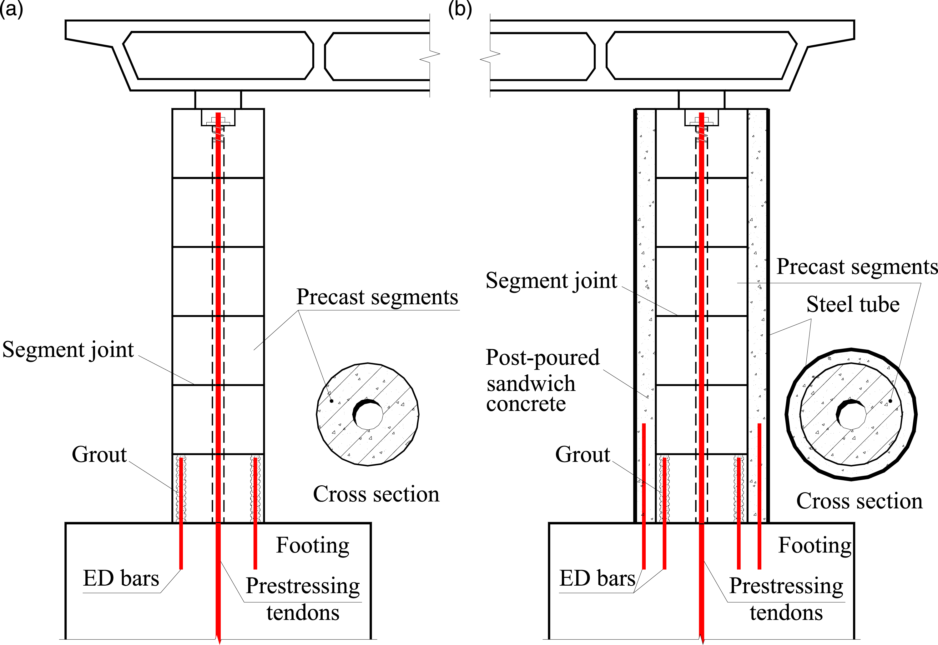
Considering the desirable behavior of concrete filled steel tube segments (Chou and Chen, 2006; Guerrini et al., 2015; Han et al., 2005; Shen et al., 2021; Xiao et al., 2005), a novel type of precast segmental bridge column confined by a grouted steel tube (TPSBC) was proposed. As shown in Figure 1(b), the core part of the TPSBC is the same as the conventional PSBC, and the grouted steel tube consists of an outer steel tube and cast-in-situ sandwich concrete. The outer steel tube does not extend into the footing. Energy dissipation (ED) steel bars (Jia et al., 2020; Shen et al., 2021; Wang et al., 2018b) or replaceable external energy dissipation devices (Chou and Chen, 2006; Guerrini et al., 2015; Marriott et al., 2009) can be further used to enhance the lateral stiffness and energy dissipation capacity of the TPSBCs. The proposed TPSBC is expected to have the following advantages. The segments will be prefabricated by centrifugal method with high production efficiency and better quality control (Zhao et al., 2019). The hollow section of the inner PSBC reduces the amount of concrete and the weight of the component. The grouted steel tube is employed to improve the integrity and torsional resistance of the PSBC under multi-directional loading. The grouted steel tube can also provide confinement to concrete at column ends and delay the concrete crushing there. The assembled inner PSBC can successfully carry the gravity load, and thus the construction of superstructures and grouted steel tube can be carried out separately after the assembly of the precast segments. The construction of the grouted steel tubes has little effects on the construction of superstructures.
Prior to the study of the seismic behavior of the TPSBCs, their axial behavior was to be studied to better understand the confinement effects of the grouted steel tubes on the segmental columns. 14 specimens were tested under axial loads to achieve the following objectives: (1) to evaluate the effects of the initial prestress levels, loading forms, outer steel tubes, the number of the precast segments, reinforcement arrangements of precast segments, and sandwich concrete strengths on the behavior of the axially loaded specimens; (2) to develop analytical models for predicting the ultimate compressive bearing capacities of the proposed TPSBCs under the different loading forms.
Experimental program
Test specimens and specimens construction
Details of the specimens.


Details of the specimens: (a) typical PSBC specimen and (b) typical TPSBC specimen.

Illustration of the specimen labels.
The specimens had the same nominal height of 1.2 m, and the slenderness ratios of the PSBCs and the TPSBCs were 4.0 and 3.2, respectively. The hollow ratio ψ p (D ci /D co ) of the precast segment was 0.3, and the hollow ratio ψ c (D ci /D si ) of the internal concrete was 0.24. D co and D ci are the outer diameter and the inner diameter of the precast hollow segment, respectively.
Specimens P2 and P3 were circular hollow reinforced concrete columns as shown in Figure 2(a). These two columns were not confined by the steel tubes for comparison purposes. The only difference between these two specimens was the number of the segments. For the proposed TPSBC, an outer steel tube with a diameter of 376 mm was employed to confine the precast concrete core. Under the condition of meeting the requirement of concrete construction, the void for the post-poured sandwich concrete was designed as small as possible to reduce the onsite labor and shorten the construction time. The outer steel tube in Figure 1(b) was placed on the footing and attached to the sandwich concrete and the precast segments through bond and friction at the interfaces. In this study, no welding rings or shear studs were welded onto the inner surface of the steel tube. Note that the use of shear studs is suggested for the columns with large diameters to ensure good long-time behavior. According to GB 50936-2014 (2014), for the circular steel tube with a diameter larger than 2.0 m or the rectangular steel tube with a cross-sectional width larger than 1.5 m, the use of shear studs is suggested. Except specimens TP1 and TP2 with one monolithic precast segment, the other TPSBC specimens had the precast concrete core consisting of three segments, as shown in Figure 2(b). Three types of reinforcement arrangements were used in the segments, as shown in Table 1 and Figure 3.
In the segmental columns, the prestress technique is usually used to improve the strength, lateral stiffness, and self-centering ability of the columns (Hewes, 2007; Zhang et al., 2021). Herein the effects of the unbond prestress on the axial behavior of the proposed TPSBC were evaluated. Specimens TP3 and TP6 with a label of P0 had no initial prestress applied to the columns, while all other specimens had the prestress about 10% of the simple superposed bearing capacity of the tested specimens (Bu et al., 2012; Cai et al., 2021). The detailed prestress (P 0 ) applied to each specimen is listed in Table 1. For each prestressed specimen, one UPPB with a diameter of 32 mm was located at the center of the cross section. The UPPB had a nominal yield strength of 1160 MPa, giving a tensile capacity of 932 kN. To investigate the effect of the prestress application sequence, the prestress of specimen TP9 was applied after the curing of the sandwich concrete, while the prestress of all other specimens under the loading form A was applied before the sandwich concrete casting.
The main construction procedures of the specimens are shown in Figure 4. Taking specimen TP7-S3B2P1 as an example, self-consolidating concrete was used to match the surfaces of the adjacent segments and adjust the verticality of the segments. The prestress was applied to the segments by tensioning the UPPB using a hollow hydraulic jack, as shown in Figure 4(e). In the process of applying the prestress, it was monitored by a calibrated load cell, and the stress-strain curves of each UPPB can be calibrated by four strain gauges affixed on the prestressing bar. Finally, a small amount of concrete was poured into the void between the steel tube and the inner PSBC. A TPSBC specimen containing an outer steel tube, sandwich concrete, and precast segments was formed. Construction of the specimens: (a) reinforcement arrangements and formwork of the segments, (b) concrete casting of the segments, (c) concrete curing of the segments, (d) segments assembly, (e) prestress applying, and (f) sandwich concrete curing.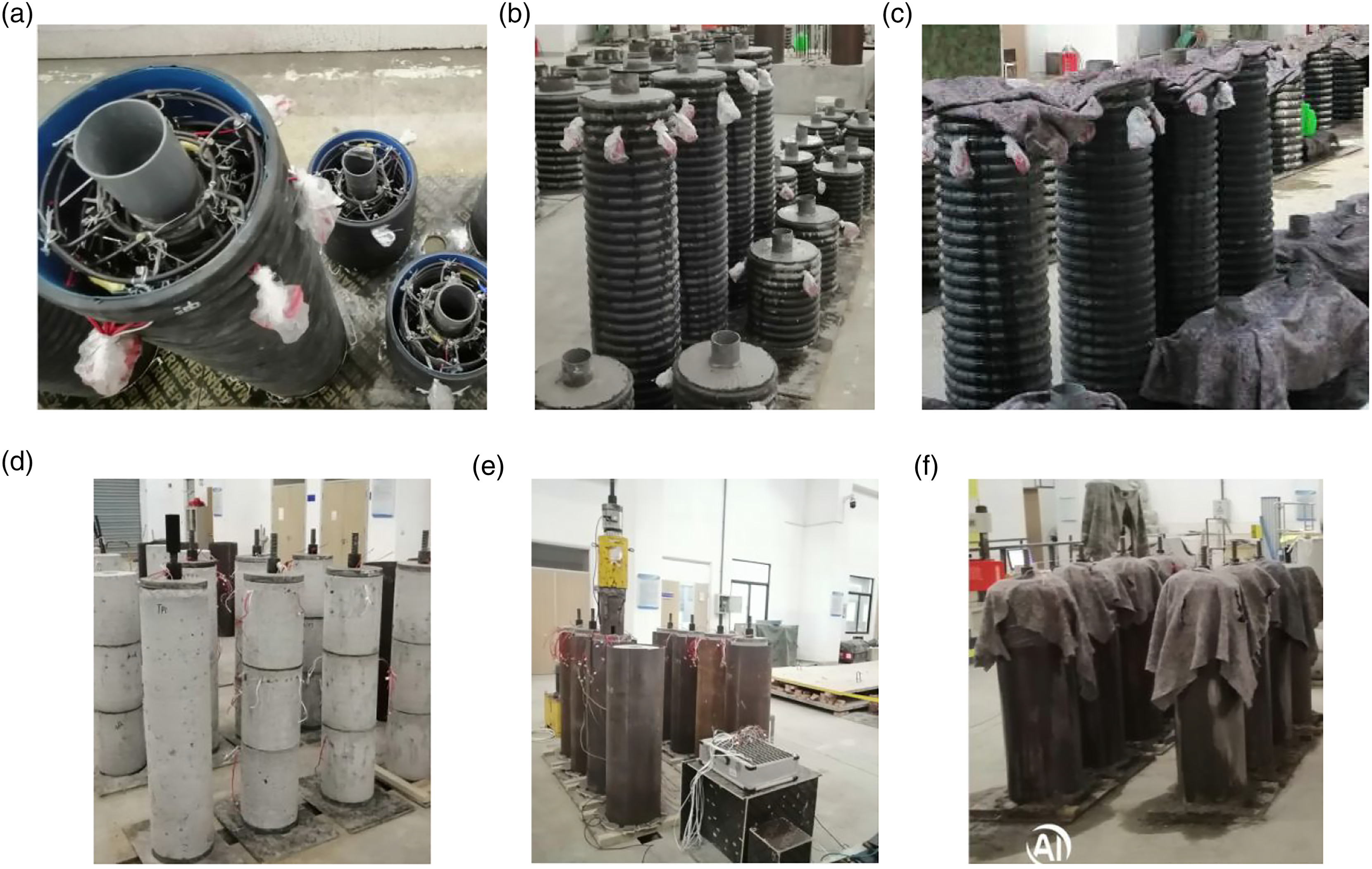
Material properties
Properties of the steel.

Commercial concrete was used for all segments and the sandwich concrete in all specimens except specimen TP10, the sandwich concrete of which was the self-consolidating concrete with higher strength. The cubic compressive strength of the segments concrete (
Experimental methods
Two types of loading forms were studied. The loading form A shown in Table 1 represented that both the prestress and the axial load were only applied to the precast segments, which was consistent with the actual local compression of the top end of the TPSBC. The loading form B represented that both the prestress and axial load were applied to the full cross-section of the TPSBC to obtain its fully loaded bearing capacity.
The specimens were axially loaded by a 7000 kN multifunctional testing machine. For the specimen with initial prestress, the UPPB protruded at two ends of the specimen. Two hollow rigid steel stub columns were specially designed and placed at the two ends of the specimen to help the application of the axial load, as shown in Figure 5. Test setup and instrumentations.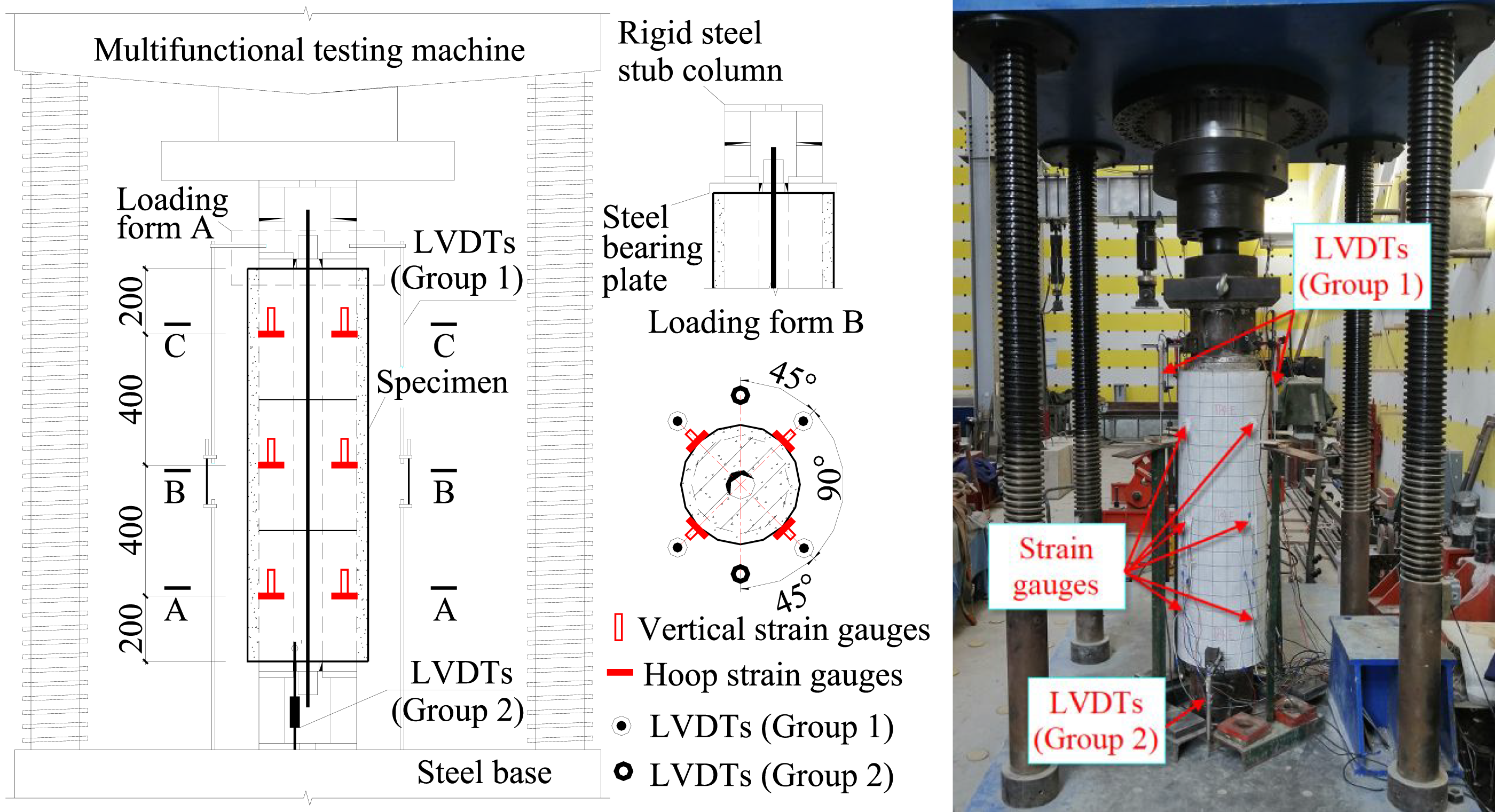
Each specimen was loaded at a rate of 0.12 mm/min before the peak load, and the loading rate gradually increased to 0.6 mm/min after the peak load. The axial loads were synchronously recorded by the data acquisition system of the testing machine. Six linear variable differential transformers (LVDTs) shown in Figure 5 were arranged along the periphery of each specimen. Four of them (Group 1) were used to measure the axial deformation from the top of the specimen to the top of the rigid steel base, and the other two LVDTs (Group 2) were used to measure the deformation of the bottom rigid steel stub column. Vertical and hoop strain gauges were affixed at the circumferential quarters of the steel tubes at sections A, B, and C. Strain gauges were also affixed on the surfaces of the steel bars and stirrups to monitor the strain development of the reinforcements.
Test results and discussion
General behavior and failure modes
Conventional PSBC specimens
The final failure of the specimens P2 and P3 was triggered by the concrete crushing, as shown in Figure 6(a)∼(c). The concrete crushing of the three-segment specimen P3 developed along the whole height of the column, while the concrete crushing of the monolithic column P2 mainly occurred at the two ends of the specimen. The different failure modes were mainly induced by the discontinuity of the reinforcements and concrete at the segmental joints in specimen P3. Different from the solid sections, the hollow sections suffered concrete crushing at both the external and the internal surfaces, and the concrete crushing near the external surfaces of the specimens was more serious than that near the internal surfaces. Failure modes of the PSBC and TPSBC specimens under the loading form B: (a) P2–S1B2P1, (b) P3–S3B2P1, (c) inward bulges of the PSBCs, (d) TP5-S3B0P1–B, (e) internal surface of TP5, (f) shear failure of internal concrete in TP5, (g) TP8-S3B2P1–B, (h) internal surface of TP8, and (i) sandwich concrete crushing of TP8.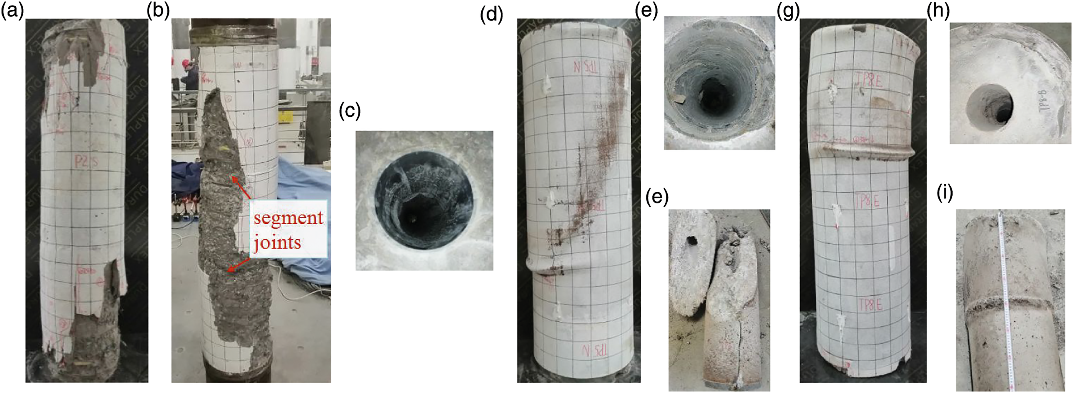
Proposed TPSBC specimens under loading form B
Specimens TP5 and TP8 were tested under the loading form B. Before the peak loads, there was no obvious change in the surfaces of the steel tubes. After the peak loads, the lateral deformations of the TPSBCs increased rapidly. For specimen TP5 without reinforcement, an inclined shear failure plane was finally formed and the inclined shear failure plane passed through the segments, sandwich concrete, and segment joint. The internal concrete was divided into two wedges, as shown in Figure 6(f). For specimen TP8 with both inner and outer reinforcements, the shear failure was successfully prevented and the steel tube locally buckled at the top segmental joint, indicating the serious concrete crushing occurred there. The failure modes of specimen TP8 are shown in Figure 6(g) ∼ (i).
Proposed TPSBC specimens under loading form A
The failure modes of the proposed TPSBC specimens under the loading form A are presented in Figure 7. For these specimens, the failure was triggered by the serious intrusion of the steel bearing plates into concrete core due to the local loading. The intrusion of the bearing plates resulted in a lot of cracks distributed along the radial direction in the sandwich concrete. At the column ends, the steel tubes bulged outward in a bud shape within the length of its diameter. The concrete damage near the internal surfaces of the hollow segments was usually more serious than that of the conventional PSBCs since the grouted steel tubes inhibited the outward expansion of the segments. Comparison of the failure processes of the specimens with different reinforcement types, it can be found the concrete crushing of the TPSBCs with both inner and outer reinforcements delayed, and the specimens exhibited slower strength deterioration than the TPSBCs without or with only inner reinforcement. It should be noted that the testing of specimen TP7 was interrupted at about 90% of its peak load due to some problems of the testing machine, and the specimen was reloaded after the machine was repaired. Failure modes of the TPSBC specimens under the loading form A: (a) TP1-S1B0P1, (b) internal surface of TP1, (c) interface of TP1, (d) TP2-S1B2P1, (e) TP3-S3B0P0, (f) TP4-S3B0P1, (g) TP6-S3B2P0, (h) end plane of TP6, (i) end part of sandwich concrete in TP6, (j) TP7-S3B2P1, (k) TP9-S3B2P1–P, (l) TP10-S3B2P1–C, (m) end part of sandwich concrete in TP10, (n) interface of TP10, (o) TP11-S3B1P1, (p) end plane of TP11, (q) segment concrete crushing of TP11, and (r) TP12-S3B2P1-T.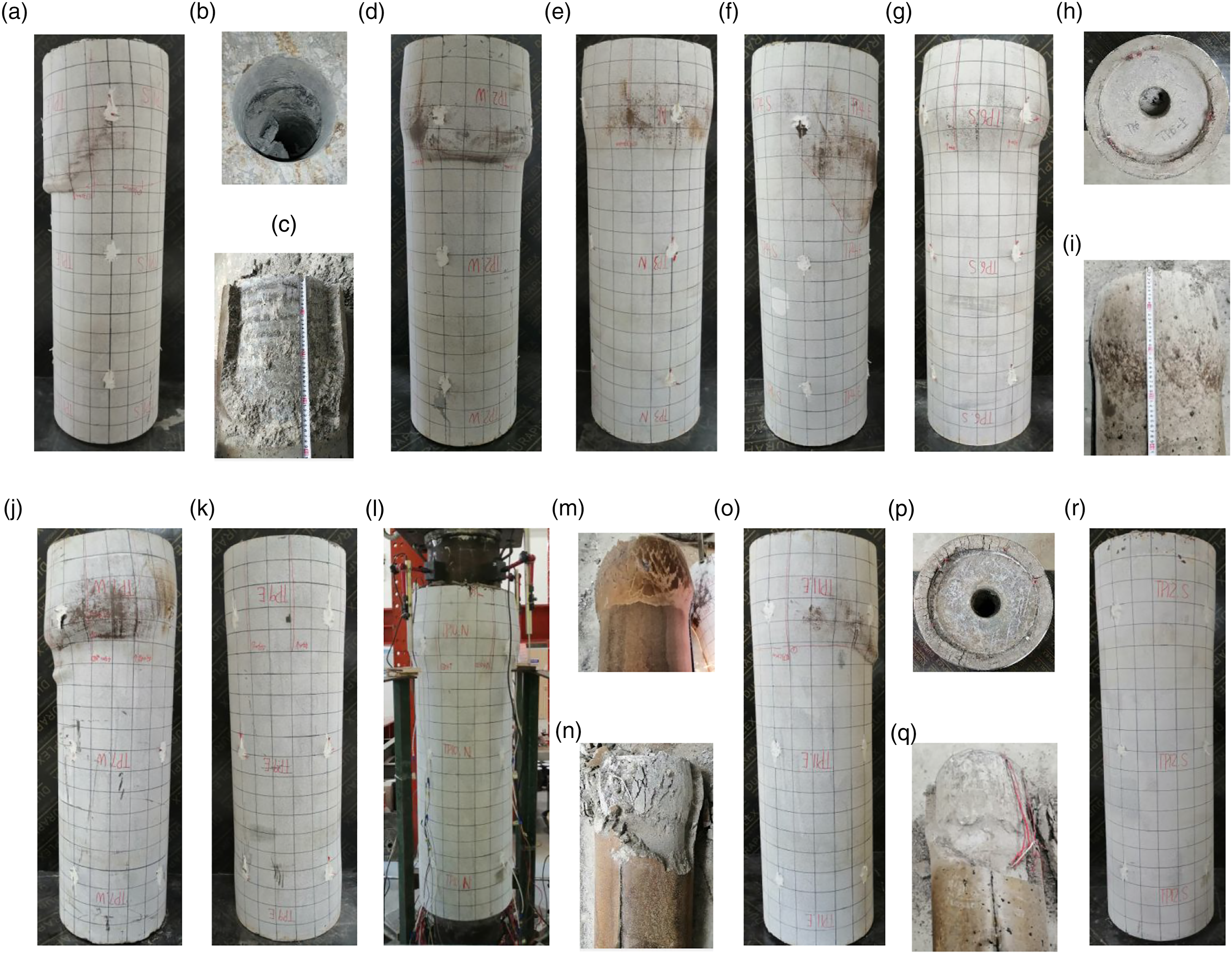
After removing the steel tubes, it can be found that, for all TPSBC specimens regardless of under the loading form A or B, the segments were well confined by the grouted steel tubes, and no visible separation between segments and sandwich concrete occurred. The proposed TPSBC specimens showed much more ductile failure than the conventional PSBC specimens did.
Effects of the parameters on the axial behavior
The axial load (N) versus average strain (ε) curves given in Figure 8 and the normalized N/N
ue
-ε/ε
ue
curves given in Figure 9 are used to evaluate the effects of the parameters on the axial compressive behavior of the specimens, where N
ue
is the experimental peak load (i.e. experimental maximum bearing capacity) of the specimen, and ε
ue
is the strain corresponding to the peak load. The average axial strain was obtained by dividing the total axial deformation (D) by the specimen length. The N
ue
and ε
ue
are shown in Table 3. In Table 3, the strength index expressed as SI=N
ue
/N
uc
is defined to evaluate the confinement efficiency of the steel tubes and the spiral stirrups (Su et al., 2021), where N
uc
is the simple superposed bearing capacity obtained by: Axial load versus average strain curves. N/N
ue
-ε/ε
ue
curves. Test results. Note: For the PSBC specimens, the N
u
is 
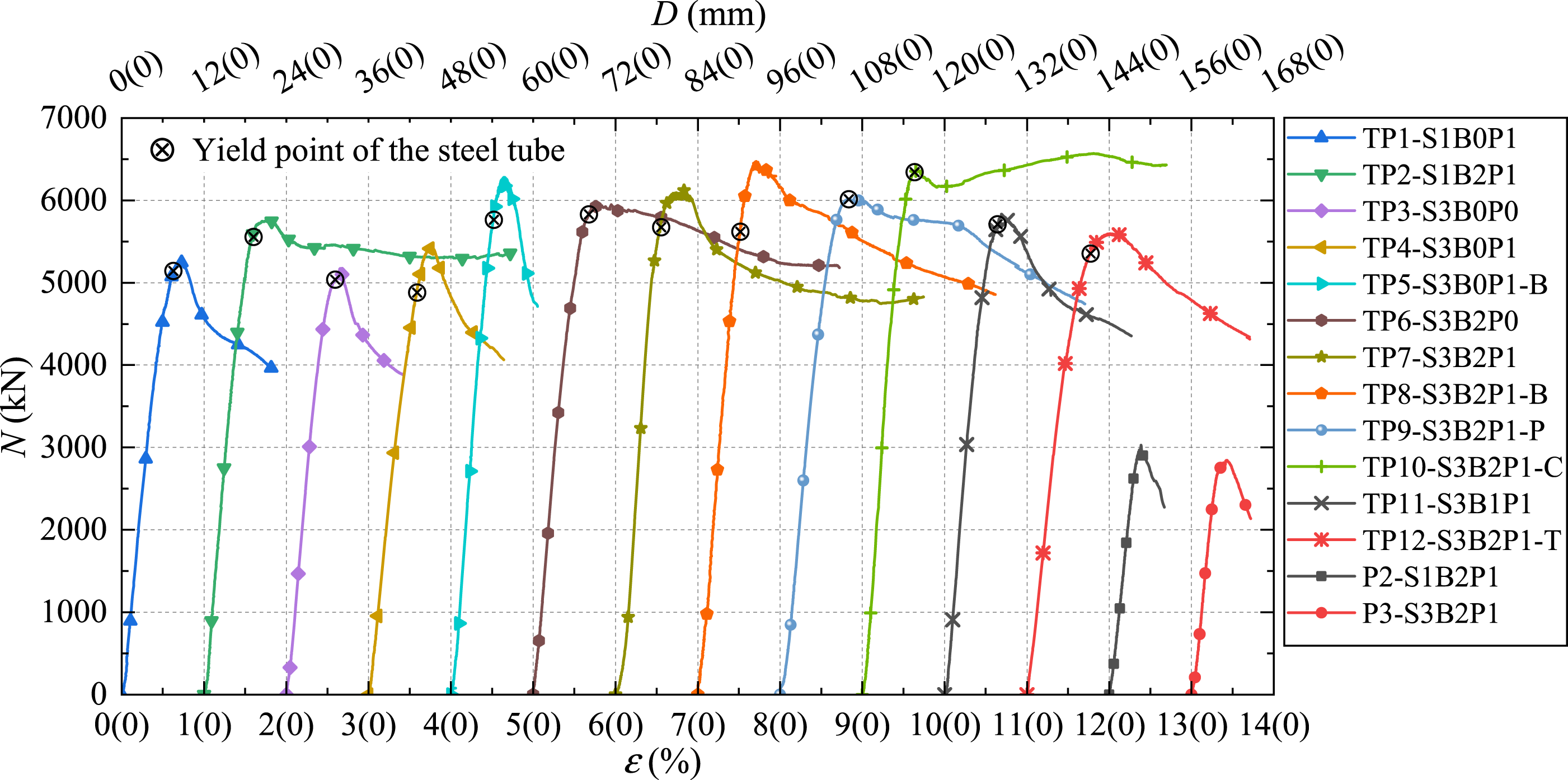
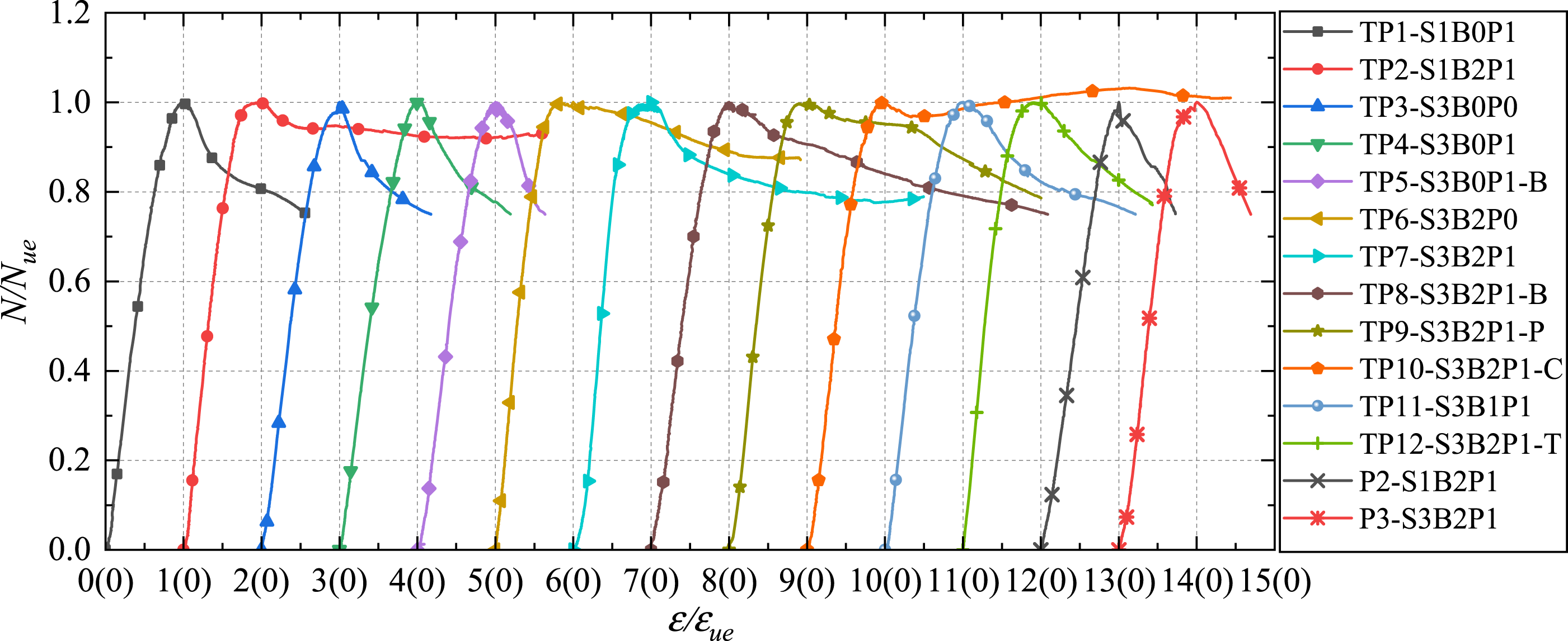

As shown in Figure 8, the N-ε curves of all specimens were basically linear in the initial stage. Subsequently, with the concrete cracking of the PSBCs or the steel tubes yielding and concrete crushing of the TPSBCs, the curves began to deviate from the initial straight lines, and the specimens entered the elastic-plastic state. The bearing capacity of specimens P2 and P3 decreased rapidly after the peak loads, which attributed to the inward deformations of the concrete due to the hollow sections. Compared with the PSBC specimens, the maximum bearing capacity of the TPSBC specimens was significantly improved. However, the bearing capacity of the TPSBC specimens without reinforcement or with only inner reinforcement decreased rapidly after the peak loads, while the TPSBC specimens with both inner and outer reinforcements showed good ductile responses.
The ductility factor (μ) is used to quantify the deformation capacity of the specimens after their yield points, and its expression is given as:
The farthest point method proposed by Feng et al. (2017) is used to determine the yield point of a specimen. The failure point is defined as the point when the axial load drops to 85% of its peak load. If the bearing capacity of the specimen decreases moderately after its peak load, the point whose deformation reaches 45 mm is taken as the failure point of the specimen. The yield loads (N y ) and yield strains corresponding to the yield points, the failure loads (N f ) and failure strains corresponding to the failure points, and the μ of the specimens are summarized in Table 3.
Effects of the prestress levels
Table 3 shows the initial prestress (P
0
) of the specimens determined by the measured strains of the UPPBs before axial loading. Figure 10 shows the deterioration of the prestress in several typical specimens. Because the free ends of the UPPBs can deformed freely without restriction due to the specially designed hollow rigid steel stub columns, it can be seen that the prestress on the specimens decreased with the increase of the applied loads and was unloaded to zero before the peak loads, indicating that the UPPBs had withdrawn from work. Therefore, the effects of the initial prestress and its application sequence on the axial compressive behavior of the specimens can be ignored. This fact can be evidenced by the comparisons shown in Table 3. As shown in Table 3, for the specimens without reinforcement (with both inner and outer reinforcements), the difference of the N
ue
between the prestressed specimen TP4 (TP7) and the non-prestressed specimen TP3 (TP6) was less than 5%. The N
ue
of specimens TP9 and TP7 with different prestress application sequence was basically the same. The N/N
ue
-ε/ε
ue
curves of specimens TP4 and TP3 without reinforcement were basically coincident. The N/N
ue
-ε/ε
ue
curves of specimens TP9 and TP6 with both inner and outer reinforcements were also similar, except that the bearing capacity of specimen TP7 may decrease rapidly after the peak load due to retest. Deterioration of the prestress.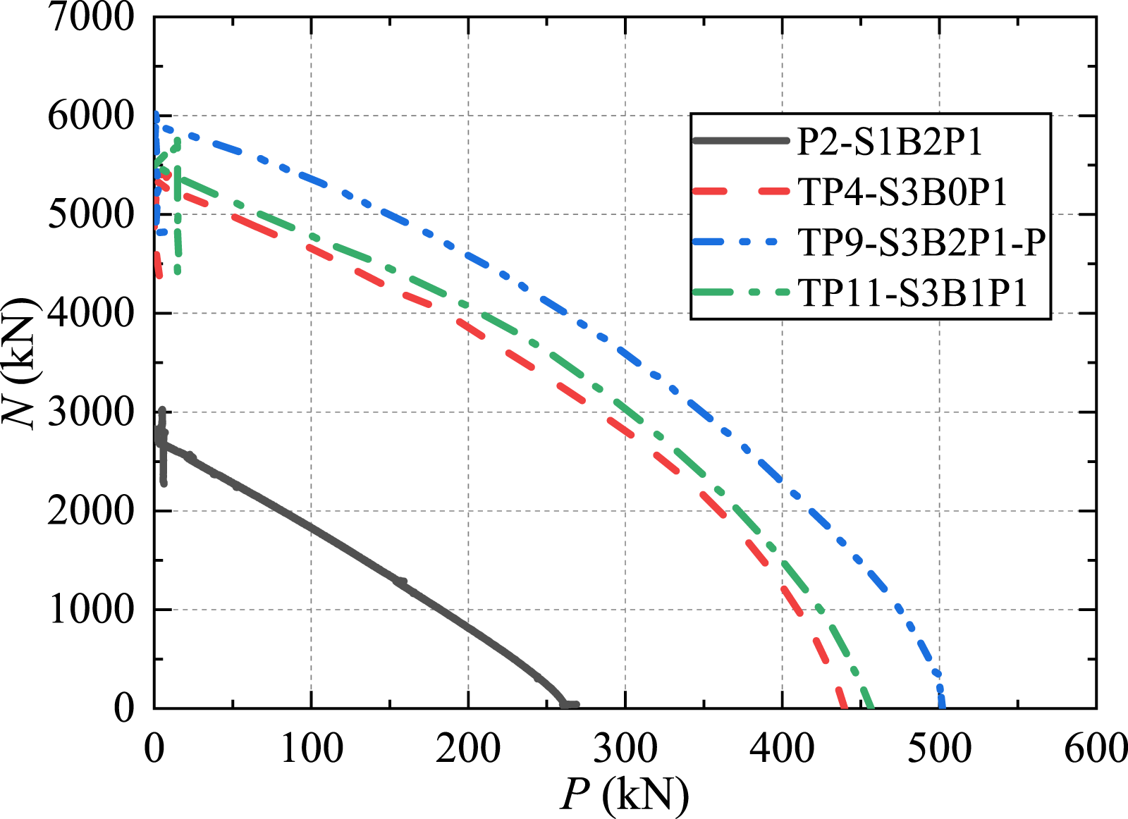
Effects of the loading forms
According to the test results of specimens TP4 (TP7) and TP5 (TP8), it can be found that the N ue of the TPSBCs under the loading form A was smaller than that of the TPSBCs under the loading form B in the case of the segments without reinforcement or with both inner and outer reinforcements. This result was attributed to the adverse local intrusion of the bearing plate, which resulted in the premature crushing of the concrete at the column ends. The comparison of the SI in Table 3 also indicated that specimens TP5 and TP8 had the SI values equal to 1.34 and 1.27, respectively, which were larger than those of other specimens under the loading form A. This result indicated that grouted steel tube provided more effective confinement to the internal concrete under the loading form B.
The ductility of the TPSBCs under the loading form A was generally better than that of the TPSBCs under the loading form B. As shown in Table 3, the μ of specimen TP4 under the loading form A was 37.4% higher than that of specimen TP5 under the loading form B, and the average μ of specimens TP6 and TP9 under the loading form A was 32.4% higher than the μ of specimen TP8 under the loading form B. Moreover, the ductility of the TPSBCs under both of the two loading forms was significantly improved when the segments were reinforced with both inner and outer reinforcements, indicating that the TPSBCs can achieve satisfactory ductility under both of the two loading forms when the reinforcements were properly arranged in the segments.
Effects of the grouted steel tubes
The effects of the grouted steel tubes were evaluated by comparison of the test results of specimens P2 (P3) and TP2 (TP6, TP7, TP9, TP12). It can be seen from Figure 8 that the grouted steel tubes significantly improved the N ue of the tested specimens. The N ue of the TPSPCs under the loading form A was 1.9–2.2 times that of the PSBCs. For the specimens with one precast segment, the μ of specimen TP2 was 3.5 times that of specimen P2. For the specimens with three precast segments, the μ of specimen TP12 was 1.6 times that of specimen P3, and the average μ of specimens TP6 and TP9 was 2.8 times that of specimen P3. Moreover, the N ue and μ of the TPSBCs increased with the decrease of the diameter-thickness ratios of the outer steel tubes. The N ue of specimen TP7 with a steel tube diameter-thickness ratio of 96 was 9.3% higher than that of specimen TP12 with a steel tube diameter-thickness ratio of 130.
Effects of the sandwich concrete strengths
The effects of the sandwich concrete strengths were evaluated by the test results of TPSBC specimens TP10 and TP7. As shown in Table 3, the SI value of specimen TP7 was 1.20, while specimen TP10 with higher sandwich concrete strength had a lower SI value equal to 1.12. The reduction of the SI value of specimen TP10 can be explained by the confinement index (
Effects of the number of the precast segments
The effects of the number of the precast segments were evaluated by the test results of PSBC specimens P2 and P3, TPSBC specimens TP1 (TP2) and TP4 (TP6, TP7, TP9) shown in Figure 8 and Figure 9. The number of the segments had no obvious effect on the N ue and ductility of the PSBCs and the TPSBCs without reinforcement, as comparison of the N-ε curves and the N/N ue -ε/ε ue curves of specimens P3 and P2 as well as those of TP4 and TP1. For the TPSBCs with both inner and outer reinforcements, the N ue of specimen TP2 with one monolithic segment was similar to the average N ue of specimens TP6, TP7 and TP9 with three segments. However, the number of the segments showed some adverse effects on the ductility of the TPSBCs with reinforcements. The μ of specimen TP6 and TP9 with three segments was 6.6% and 26.9% less than that of specimen TP2 with one segment, respectively. It should be noted that both specimens TP6 and TP9 exhibited ductile behavior with the ductility factor of 6.70 and 5.24, respectively. Therefore, the adverse effects of the number of the segments on the axial compressive behavior of the specimens can be ignored. Similar conclusions were drawn by the study performed by Wu et al. (2018).
Effects of the reinforcements in the precast segments
The use of the reinforcements in the segments improved the N ue of the TPSBCs under the same loading forms, as shown in Table 3. The effect of the inner spiral stirrups was evaluated by comparison of the test results of specimens TP4 and TP11. The N ue of specimen TP11 was approximately equal to the sum of the N ue of specimen TP4 and the compressive capacity of six longitudinal steel bars with a diameter of 14 mm, indicating that the inner spiral stirrups can hardly provide hoop confinement to the hollow segments. The outer spiral stirrups, however, can effectively confine the internal concrete under the loading form A. Specimens TP2 with outer spiral stirrups had the N ue greater than the sum of the N ue of specimens TP1 without reinforcement and the compressive capacity of 12 longitudinal steel bars with a diameter of 10 mm. The same conclusion can be drawn from the results of specimens TP6 and TP7. However, the confinement effects of the outer spiral stirrups reduced when the specimens were under the loading form B, as evidenced by the comparison of the test results of specimensTP8 and TP5. This may be attributed to the premature concrete crushing near its segment joint.
As shown in Table 3, for the TPSBCs with one monolithic segment under the loading form A, the μ of specimen TP2 with both inner and outer reinforcements was 2.8 times that of specimen TP1 without reinforcement. For the TPSBCs with three segments under the loading form A, the μ of specimen TP6 with both inner and outer reinforcements was 2.6 times the average μ of specimens TP3 and TP4 without reinforcement. For the TPSBCs with three segments under the loading form B, the μ of specimen TP8 with both inner and outer reinforcements was 2.2 times that of specimen TP5 without reinforcement. The μ of specimen TP11 with only inner reinforcement was only 14.0% higher than that of specimen TP4 without reinforcement, and the μ of the TPSBCs without reinforcement was close to that of the PSBCs. The above results showed that it was necessary to arrange the inner and outer reinforcements in the hollow segments in order to achieve a ductile manner for the TPSBCs.
Axial load versus steel strain analysis
When PSBC specimens were loaded to about 85% of their peak loads, cracks in the concrete cover and yielding of the longitudinal steel bars were observed. However, the bearing capacity increased owing to the increased confinement of the outer spiral stirrups.
The N-ε curves and the N–U curves of the steel tubes for typical TPSBCs are depicted in Figure 11, where ε
vA
(ε
vB
, ε
vC
) and ε
hA
(ε
hB
, ε
hC
) are the average vertical and hoop strains at section A (B, C), respectively, and the transverse deformation coefficient U is the absolute value of the ratio of the average hoop strain ε
h
to vertical strain ε
v
at the same section. N-ε curves and N–U curves of the outer steel tubes for typical TPSBCs: (a) N-ε curves of TP2-S1B2P1, (b) N–U curves of TP2-S1B2P1, (c) N-ε curves of TP8-S3B2P1–B, (d) N–U curves of TP8-S3B2P1–B, (e) N-ε curves of TP10-S3B2P1–C, and (f) N–U curves of TP10-S3B2P1–C.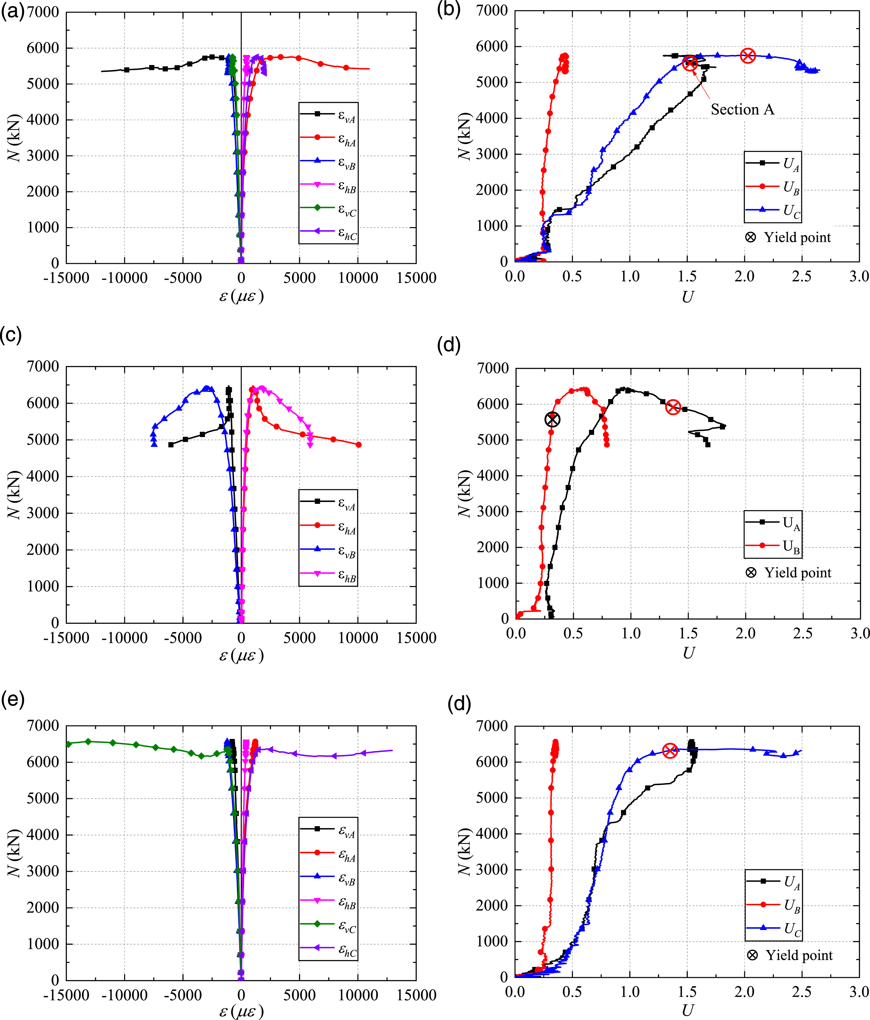
For the two types of steel tubes with diameter-thickness ratios of 96 and 130, the compressive stress p on the surfaces of the steel tubes was about 2.1% and 1.5% of the hoop stress σ
h
in the walls of the steel tubes, respectively. Therefore, the yield point f
yt
of the steel tube can be determined according to Von Mises criterion as follows (Liu and Zhou, 2010):


As shown in Figure 11, the axial load versus the vertical and hoop strain curves at each section of the TPSBCs increased linearly with the increase of the axial load in the initial stage. It can be seen from Figure 8 that the steel tubes of the specimens yielded firstly near the peak loads. After the peak loads, the strain development of the TPSBCs under the different loading forms was quite different. Specimen TP8 under the loading form B had large strain at the middle section B, while the large strain occurred at the column ends of the specimens under the loading form A due to the intrusion of the bearing plates. The intrusion of the bearing plates resulted in the transverse deformation coefficients at sections A and C greater than 1.0 at the peak loads. For specimen TP8 under the loading form B, the transverse deformation coefficients were less than 1.0 at the peak load because the steel tube resisted the vertical load directly together with the internal concrete.
The development of the transverse deformation coefficients at the middle section B of the TPSBCs under the loading form A was basically the same as that of specimen TP8, which meant that the middle part of the TPSBCs had a similar stress state under the loading forms A and B due to good load transferring between the internal concrete and the steel tube by the bond and friction. According to the failure modes of the specimens and the lateral deformation coefficient development of the steel tubes, the reason why the N ue of the TPSBC under the loading form A was less than that of the TPSBC under the loading form B can be well explained.
Analytical models
For the TPSBC under the loading form B, its axial compressive behavior is similar to that of the concrete-filled steel tubular columns (Ci et al., 2022; Han et al., 2008, 2014; Li et al., 2017; Zhao et al., 2019). Three types of confined concrete are considered due to the different strengths of the segment concrete and sandwich concrete, and different lateral confinements, as shown in Figure 12. The strength of the concrete The cross section divisions.

For the concrete confined by the steel tube:
For the concrete confined by the spiral stirrup:
According to the related research (Liu and Zhou, 2010; Wang et al., 2019) and the above analysis, the compressive capacity of the longitudinal steel bars can be directly added to the compressive bearing capacity of the composite column. Therefore, the ultimate bearing capacity of the fully loaded TPSBC can be calculated as:
By introducing equations (7) ∼ (9), the equation (10) becomes:
For the TPSBC under the loading form A, a strength reduction factor was introduced to consider the local compression effect on the concrete and it can be conservatively taken as 
The ultimate bearing capacity of the locally loaded TPSBC can be calculated as:
For the convenience of analysis and superposition, the reduction factor
By introducing equation (12), the equation (13) becomes:
The ultimate bearing capacity of the PSBCs can be calculated as:
Table 3 presents the ultimate bearing capacity of all specimens calculated by the proposed analytical models. As shown in Table 3, the calculated bearing capacity is less than the experimental peak load (N ue ) in almost of all specimens except specimen TP8, the calculated bearing capacity of which is slightly greater than its N ue due to the premature concrete crushing near the segment joint. The performance of the analytical models is further evaluated by the mean value (MV) and the standard deviation (SD) of the ratios of the N ue to the calculated values. The MVs of the PSBC specimens and TPSBC specimens under the loading form B are 1.119 and 1.039, respectively. The MV and SD of the TPSBC specimens under the loading form B are 1.082 and 0.027, respectively. The proposed analytical models give a relatively rational prediction of the ultimate bearing capacity of the PSBC and TPSBC specimens. However, due to lack of enough experimental results, the size effects of the proposed TPSBC columns were not considered in the analytical models. Therefore, further research is still necessary to study the size effects of hollow TPSBC columns with reinforcements, and more parametric studies are still needed to validate the feasibility of the proposed analytical models.
Conclusions
The axial compressive behavior of the proposed TPSBC was investigated by testing of 14 specimens. Based on the experimental results and discussion presented in this paper, the following conclusions can be drawn: 1. The final failure of the conventional PSBC specimens was induced by the concrete crushing, and the concrete damage was more serious near segment joints due to the discontinuity of the reinforcements and concrete. The proposed TPSBC achieved a desirable ductile failure due to the use of grouted steel tubes. 2. The loading forms and the reinforcement arrangements in the precast hollow segments affected the failure modes of the proposed TPSBC specimens. For the specimens under the loading form B (full compression), the inclined shear failure finally occurred in the specimens without reinforcement, while the specimens with both inner and outer reinforcements failed with concrete crushing at the segment joints and outward local buckling of the steel tube. For the specimens under the loading from A (local compression), the steel tube of each TPSBC bulged outward in a bud shape within the length of its diameter, and the concrete inside the steel tubes underwent large plastic deformation and was finally crushed. 3. The loading forms affected the maximum bearing capacity and the ductility of the TPSBCs with hollow sections. The maximum bearing capacity decreased with the decrease of the compression area; however, the ductility factors of the specimens under local compression were higher from a range between 32.4% and 37.4% than that of the specimens under full compression. 4. The prestress used to clamp the precast segments together and the number of the precast segments had little effect on the maximum bearing capacity and ductility of the TPSBC specimens. 5. The use of grouted steel tubes significantly improved the axial compressive behavior of the specimens. The maximum bearing capacity and the ductility factors of the TPSBCs were more than 1.9 and 1.6 times those of the PSBCs, respectively. The increase of the sandwich concrete strengths significantly improved the ductility of the specimens under local compression, while the increase of the diameter-thickness ratios of the outer steel tubes deteriorated the maximum bearing capacity and the ductility of the TPSBCs. 6. With proper consideration of the loading forms, and the combined confinement effects of the steel tube and the outer spiral stirrups, analytical models were developed for predicting the ultimate bearing capacity of the TPSBCs. The calculated results were in good agreement with the experimental peak loads.
The good behavior of the proposed TPSBC under axial compression has already been verified with tests of 14 stub columns. The authors have also verified the desirable seismic performance of the proposed TPSBC, and the test results will be reported later. To extend the application of TPSBC in seismic zones, further research is still necessary to validate the developed analytical models with more experimental results and investigate the behavior of the columns under complicated loading conditions.
Footnotes
Declaration of conflicting interests
The author(s) declared no potential conflicts of interest with respect to the research, authorship, and/or publication of this article.
Funding
The author(s) disclosed receipt of the following financial support for the research, authorship, and/or publication of this article: The research reported was carried out under the support of the National Natural Science Foundation of China (No. 51978656) and Jiangsu Key Laboratory of Environmental Impact and Structural Safety in Engineering, China University of Mining & Technology (No. KFJJ202004).
