
Abstract
A new brace-type slit damper, called ‘Circular Tube-in-Tube Damper (C-TTD), comprises two solid steel cylinders and one circular cross-section tube equipped with slotted holes, is proposed for seismic resilience of structures. In the proposed damper, a system of bolts was used to connect up various components of the damper, allowing inspection and replacement of the damaged components without any requirement for the replacement of the entire damper. Nonlinear finite element analyses using ABAQUS were carried out to verify the experimental results and to investigate the effect of damper geometric properties on the yield load capacity of the C-TTD dampers. The seismic performance characteristics of 4-storey, 8-storey, and 15-storey steel structures equipped with C-TTD dampers were determined by nonlinear time history analyses using three different earthquake excitations. The results indicated that when the structures were equipped with C-TTD dampers, the inter storey drift decreased in the range of 8%–55%, the base shear load decreased in the range of 27%–35%, and the input energy decreased in the range of 70%–80%, depending on the number of storeys and the earthquake type, compared to the counterpart structures without the damper.
Introduction
Vibration control is a set of technical methods used to alleviate the impacts of seismic loading on structures by absorbing and dissipating a high percentage of vibration energy and therefore decreasing the displacement of structures without the need for retrofitting individual structural elements. Among all vibration control systems, dampers are considered to be an economical and practical solution and are widely used for the dynamic retrofitting of structures (Council et al., 1997). The most common type of dampers is metal dampers that dissipate the energy of vibration by damper material yielding through axial, shear, and flexural deformation mechanisms (Teruna et al., 2015). Metal dampers are categorised into several groups, of them the most popular are (1) Steel Slit Dampers (SSD), (2) Buckling Restrained Brace dampers (BRB), and (3) Tube-in-Tube Dampers (TTD) (Oh et al., 2009; Takeuchi et al., 2012; Teruna et al., 2015) SSD dampers are composed of one or multiple slotted sheets that dissipate the vibration energy through shear and flexural deformation mechanisms (Chan and Albermani, 2008; Ghabraie et al., 2010; Lee et al., 2015; Zheng et al., 2015). BRB dampers consist of a steel tube surrounding a metal core, where the space between the tube and the core is filled with concrete or mortar. The central core of the BRB withstands high values of axial loads, while the outer tube, which is filled with concrete or mortar, prevents buckling of the metal core when subjected to axial compressive stresses (Filip-Vacarescu et al., 2016; Iwata et al., 2000).
SSD dampers should be embedded in a structure such a way that they sustain plastic behavior before the structural elements (Aghlara and Tahir, 2018; Aminzadeh et al., 2020; Bayat and Shekastehband, 2019). While the SSD dampers are required to be mounted on secondary structures such as bracing systems for vibration dissipation of the structures (Amiri et al., 2018; Lee et al., 2015; Teruna et al., 2015), BRB dampers are directly integrated with the primary structural system. This poses a problem post-seismic loading as non-destructive testing methods cannot be used to examine the metal core and the surrounding concrete/mortar needs to be physically removed to conduct an examination (Tremblay et al., 2006). However, the major disadvantage of this system is the limitations associated with the quality control of the system for which demolishing of the damper is required.
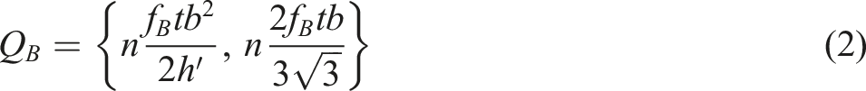
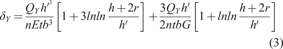
TTD dampers were developed to address the drawbacks associated with SSD and BRB dampers, with TTD dampers consisting of an outer and an inner square hollow section tube with different lengths that are connected using a combination of plug and fillet weld. The outer tube consists of a series of strips and slits, with the energy of vibration dissipating via elastic and inelastic deformation of the strips (see Figure 1(a)) (Benavent-Climent, 2010). Benavent-Climent showed that the SSD dampers design equations could be used for the design of TTD dampers: Geometric properties of TTD dampers [14]. (a) TTD damper (b) Details of the energy-dissipative part and equivalent strip of TTD damper. TTD: Tube-in-Tube Damper.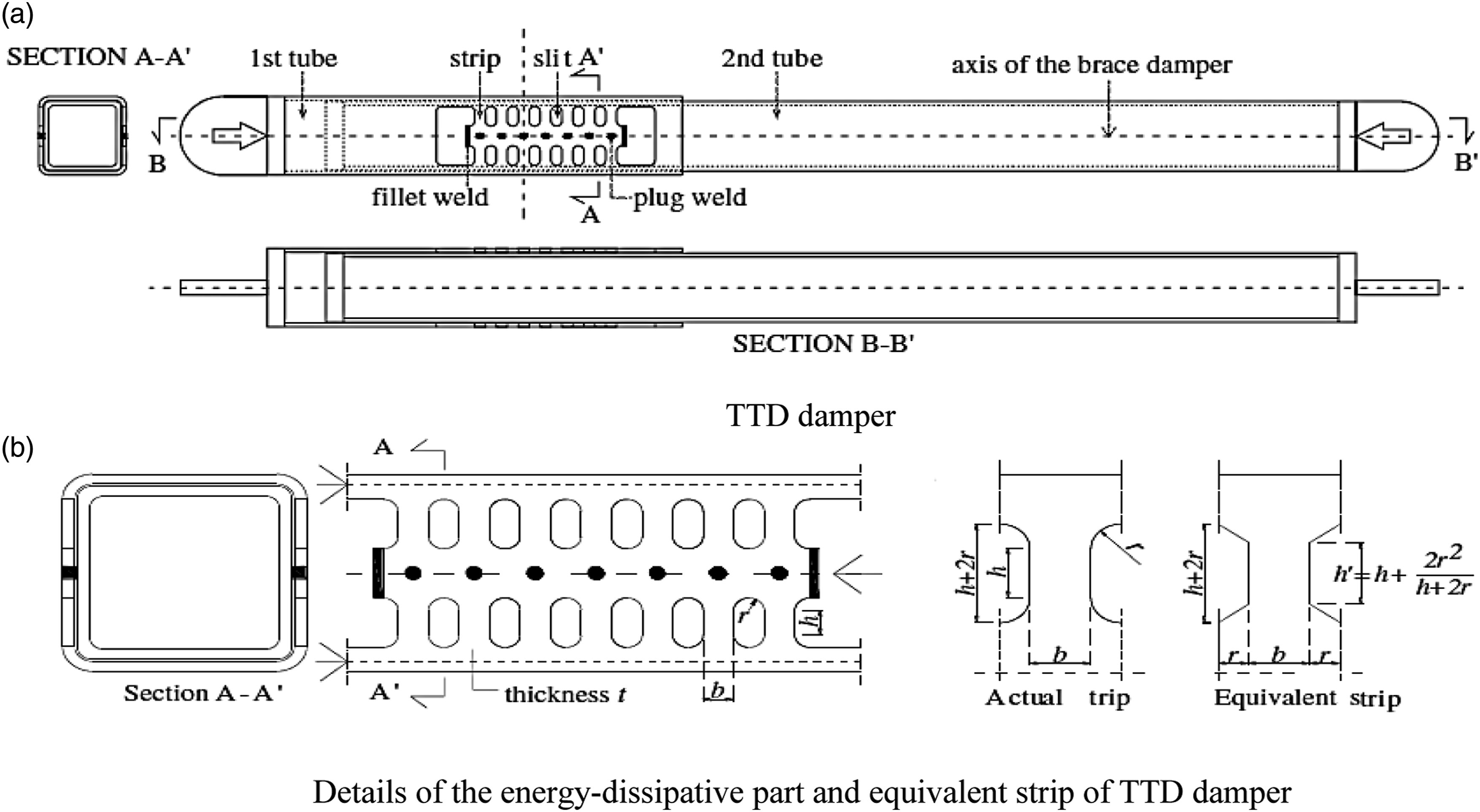


In TTD dampers, stress concentration occurs at the corners of the square hollow section tubes and consequently causes the fracture of the tubes. Additionally, the whole system of the TTD damper needs to be replaced after any failure associated with the components of the TTD dampers because these dampers are connected via welds (Benavent-Climent, 2010). In the reported study herein, circular cross-section tubes were used to replace square hollow section tubes in the TTD dampers to eliminate the stress concentration at the corners of the square cross-section tubes. Additionally, a system of bolts was used to replace welds in TTD dampers to connect up the various components of the damper, with the use of bolts allowing inspection and replacement of the damaged components without any requirement for the replacement of the entire damper. The proposed damper is identified as ‘Circular Tube-in-Tube Damper’ (C-TTD). In this study, the effect of strip and slit dimensions on the yielding load of the C-TTD dampers was investigated, and then the seismic performance characteristics 4-storey, 8-storey, and 15-storey steel structures with and without a C-TTD damper that were subjected to various earthquake scenarios was investigated.
C-TTD damper manufacture
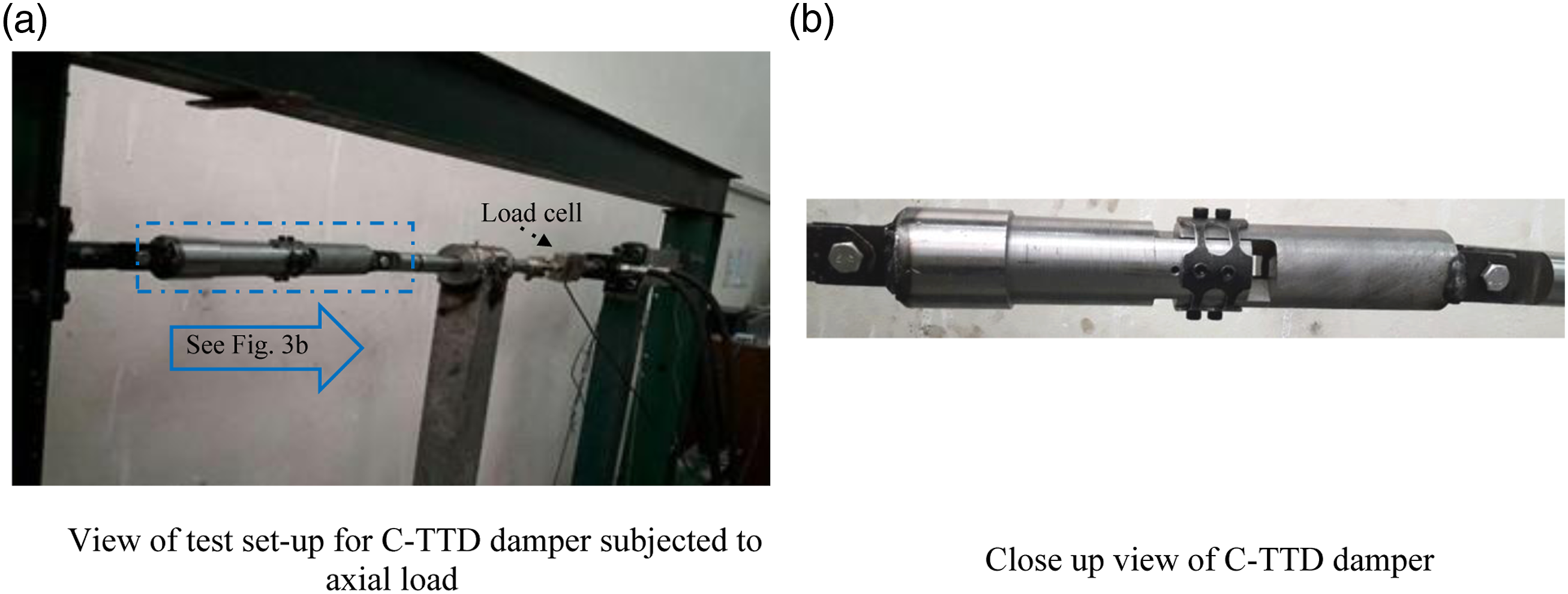
A C-TTD damper was composed of two steel solid cylinders and one circular cross-section tube. At one end of each of the two solid cylinders, two 89° sectors (for eliminate contact between sectors and therefore eliminate the friction when the sectors slide into each other) and a hole with 15 mm diameter having a depth of 66 mm were removed (see Figure 2(a)). The steel solid cylinders were assembled with a 90° phase difference such that the unremoved sectors could slide into the removed sectors with no friction by creating several special cuts, while at the other end of these solid steel cylinders, there were connecting plates with a hole to connect the damper to the frame using a pinned support (Figure 2(c)). A series of strips were created by cutting a series of slits on the circular cross-section tube. The corners of the slits were rounded to prevent stress concentration at the corners of the slits (Figure 2(b)). This tube was connected up to the steel solid cylinders using bolts (see Figure 2(d)). The energy of vibration was dissipated by C-TTD damper via flexural/shear yielding of the strips. The circular cross-section tube that overlapped the solid cylinders prevented any out-of-plane movement of the damper (see Figure 2(d)). The overlapping length of the circular cross-section tube was not manufactured for ease of construction and due to limitations associated with the laboratory facilities and equipment (see Figure 3(b)). Details of circular tube-in-tube damper . (a) Schematic details of steel solid cylinders (b) Circular cross-section tube with several strips on wall (c) Assembly of steel solid cylinders (d) Assemble all parts of damper. Details of test set-up. (a) View of test set-up for C-TTD damper subjected to axial load (b) Close up view of C-TTD damper. C-TTD: Circular Tube-in-Tube Damper.
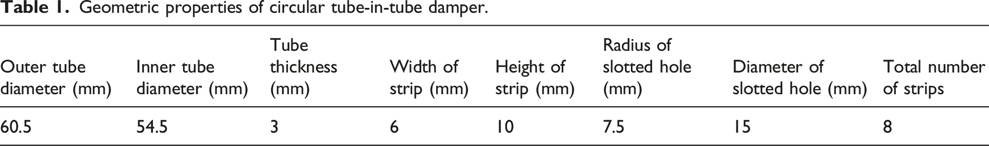
Geometric properties of circular tube-in-tube damper.
Experimental study
One end of the C-TTD damper was attached to a pinned support bolted to a portal frame to constrain the damper against any axial movement, and the other end of the damper was attached to an actuator using a pinned support (see Figure 3(a)). The test procedure involved applying axial harmonic sinusoidal load with a frequency of 0.5 Hz and a maximum amplitude of 3.5 mm. The strips behaved as a series of fixed-ended beams and deformed in double curvature when the damper was subjected to sinusoidal harmonic load. The energy of the cyclic loading dissipated through shear and flexural yielding at strips.
A total of three cycles of axial harmonic sinusoidal loading were applied on the damper during the experimental program, with the associated hysteresis curves for axial load versus strip displacement being presented in Figure 4. The results showed that the hysteretic response was stable and symmetric, and the maximum compression and tensile loading values were approximately the same, indicating negligible energy dissipation due to friction between the components of the damper. Also, the shape of the loops, which was close to a rectangle, indicated an excellent energy dissipation capability of the damper. Hysteresis curve and backbone curve. (a) Axial load-displacement relationship of circular tube-in-tube damper (b) Backbone curve.
Design parameters of circular tube-in-tube damper.

The metallic yielding devices are categorised as displacement dependent instruments (independent from the loading rate), in which effective damping and stiffness are the two most important nonlinear features for analytical modelling. The effective stiffness (K
eff
, see Figure 4(a)), is calculated using equation (5) to determine the elastic strain energy (E
es
) and the restoring force of the damper (K
eff
(|δ
max
+| + |δ
max
−|)/2) in each cycle.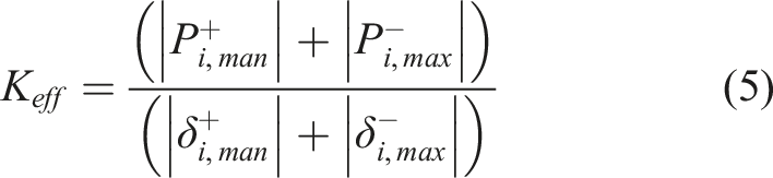
The effective damping of a system indicates the energy dissipation capacity of a device, which is related to the displacement of the device. The effective damping of a device (β
eff
) is calculated using equation (6)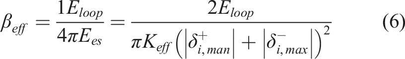
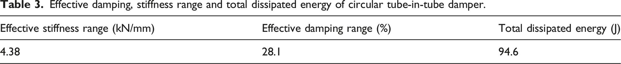
Effective damping, stiffness range and total dissipated energy of circular tube-in-tube damper.
The deformation of the strips during the experiment is shown in Figure 5. Test configuration of circular tube-in-tube damper.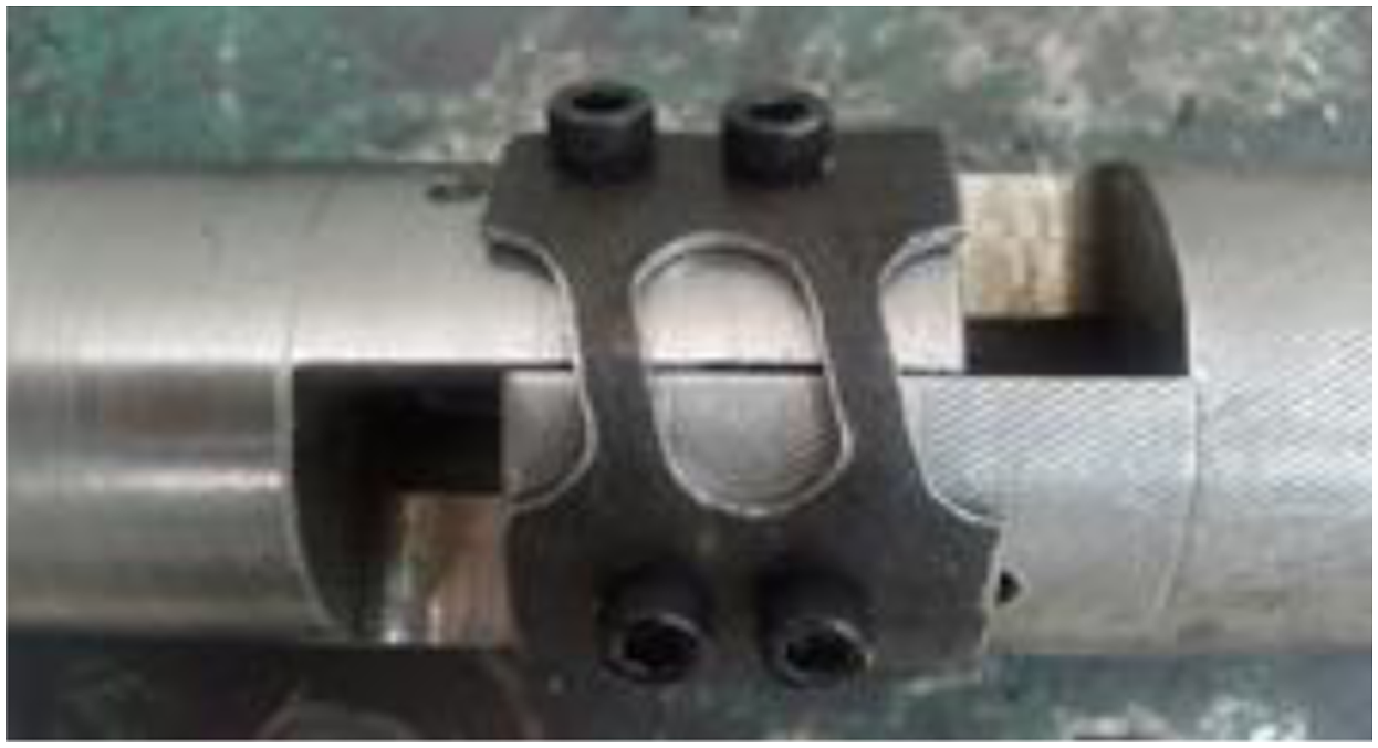
The strips behaved as a series of fixed-ended beams and deformed double curvature when the damper was subjected to axial load. The ultimate displacement of the C-TTD damper depends on the dimension of the strips, similar to SSD dampers; therefore, selecting the strips that are proportional to the scale of the structure will visit the deformation demand of the structures.
Numerical modelling
The general-purpose finite element (FE) program ABAQUS was employed to develop a nonlinear elastic-plastic FE model for the C-TTD damper when subjected to harmonic loading. Material properties were modelled using true stress-strain values calculated from engineering stress-strain relationships, which were obtained from the tensile test on circular cross-section tubes, with the averaged results given in Figure 6. Stress-strain relationship of circular tube-in-tube damper material. (a) Average engineering stress-strain relationship (b) Close-up view of the stress-strain relationship within elastic range.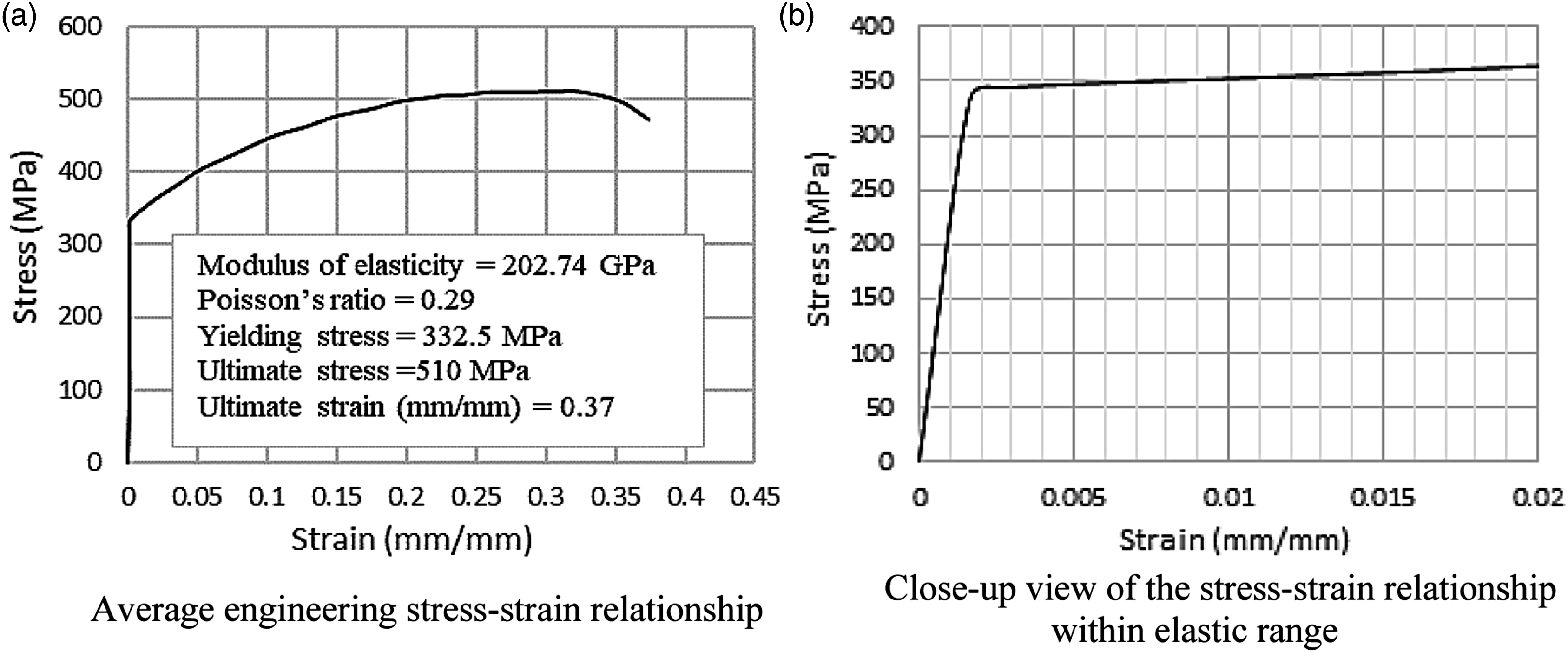
C3D20R solid elements were used to model steel tubes. The C3D20R (twenty-node brick element with reduced integration) element is a general-purpose quadratic brick element, with reduced integration (2 × 2 × 2 integration points). This element properly simulates the mechanical behaviour of isotropic materials in bending and rarely exhibits hour glassing despite the reduced integration. The General Contact algorithm was used to model the contact between the steel rigid cylinders and circular cross-section tube. Smaller mesh size was used to model the circular cross-section tube when compared to cylinders because a higher level of stress concentration occurred in the tube. Only one-fourth of the specimen was modelled due to the symmetry of the model (Figure 7). Finite element model of circular tube-in-tube damper.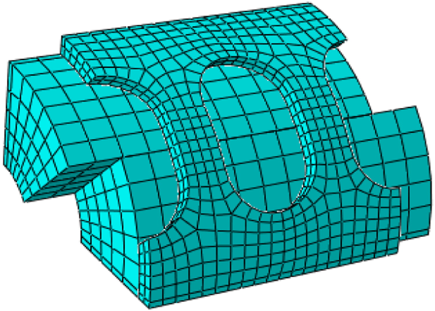
One of the steel solid cylinders was constrained against axial displacement (z-direction for the longitudinal direction of the tube) and a harmonic displacement (f = 0.5 Hz and PGD = 3.5 mm) was applied at the other end of the steel solid cylinder, as shown in Figure 8. Harmonic loading protocol.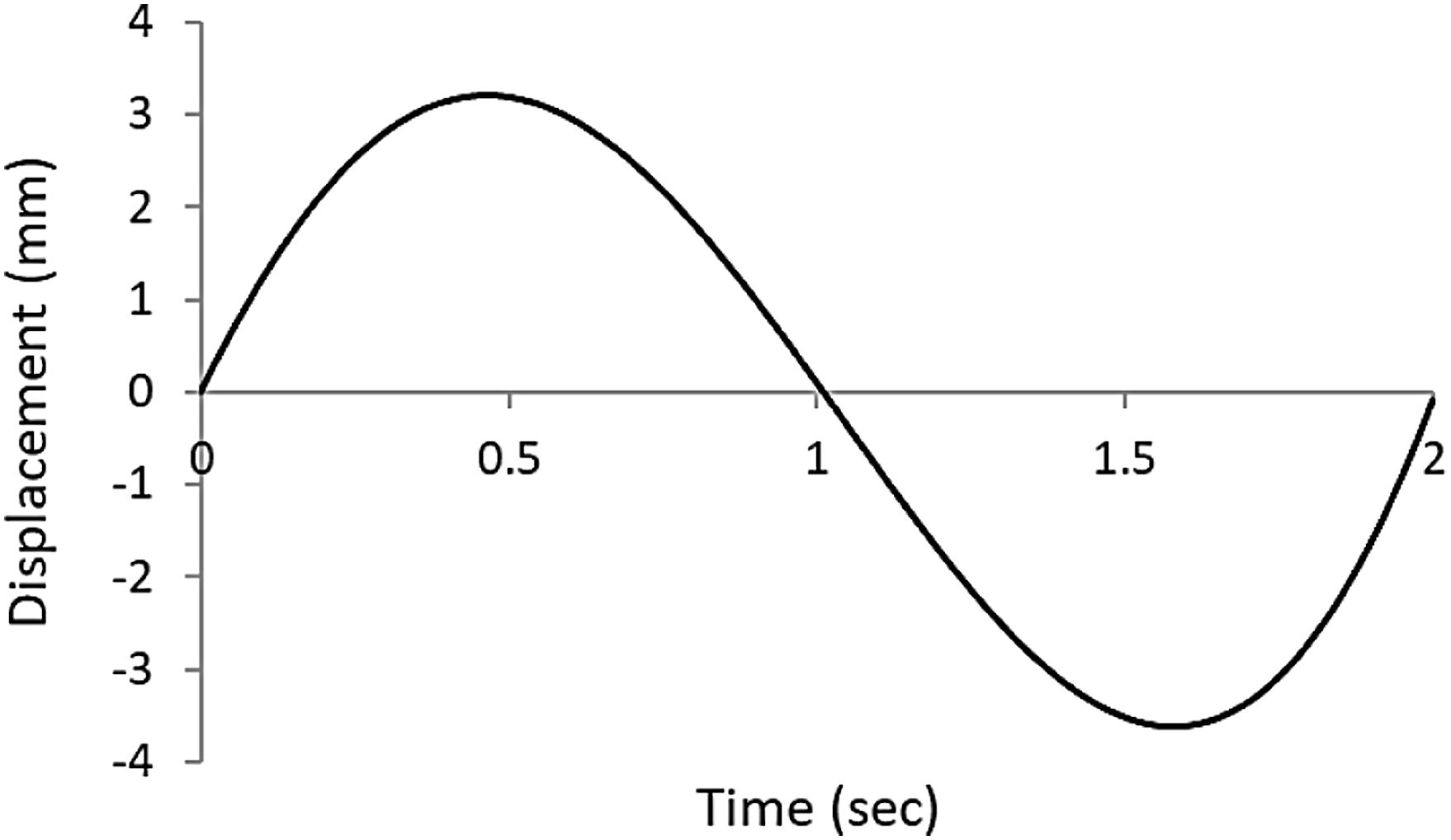
The system was subjected to an implicit dynamic analysis. Figure 9 shows the results of the analysis along with the strain rate for the C-TTD damper. Energy is dissipated by the shear/bending yields of the strips (see Figure 9). Equivalent plastic strain at the maximum displacement of finite element model.
In Figure 10, the axial load versus strip displacement of the C-TTD damper obtained from experiment and FE analysis are compared, with the results showing a good correlation between the test and the numerical simulation. The numerical model showed a stable and symmetric response, and the elastic and post-elastic stiffness of the model were equal at both tensile and compression modes. From Figure 10, it can be deduced that the damper yielded at a small displacement (δ
y
= 0.26 mm) and exhibited a stable hysteretic behaviour with a gradual transition between the elastic and inelastic regimes. Its yielding force and its yielding displacement agree with those obtained experimentally and with the simplified models. Total dissipated energy obtained from experiment and FE analysis were 94.6 J and 103.97 J that had 9% difference from each other. Experimental versus numerical responses.
Parametric study
A parametric study was conducted to investigate the effect of wall thickness, width and height of strips, the diameter of slotted holes and diameter of circular cross-section tube on the damper designing parameters using FE analysis. 20 models were constructed and the hysteresis curves for varying parameters obtained from the FE analysis are compared in Figure 11. Axial load-displacement relationship obtained from finite element analysis. (a) Effect of strip width (b) Effect of strip thickness (c) Effect of diameter of the slotted holes (d) Effect of strip height (e) Effect of circular tube diameter.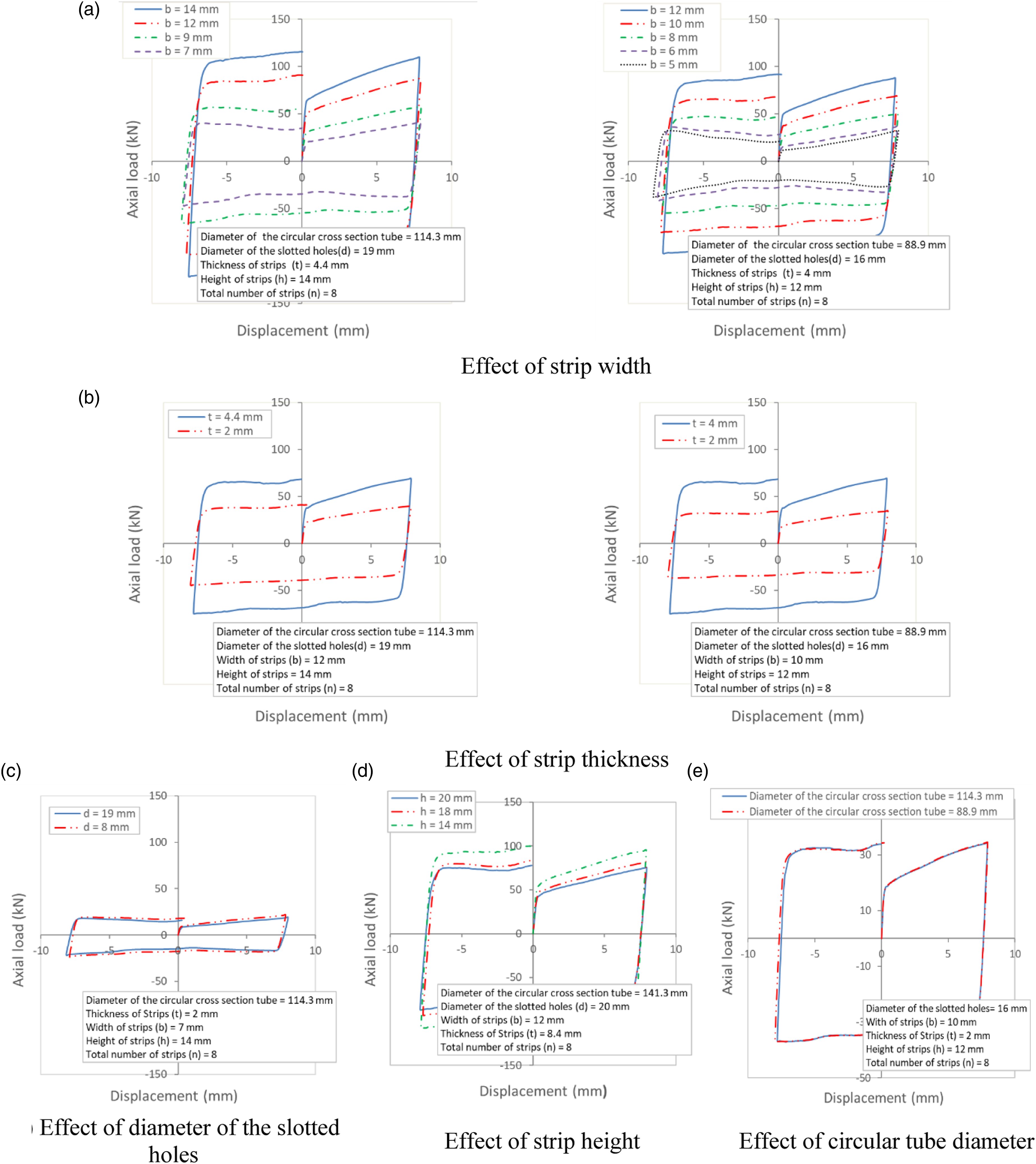
Each specimen assigning with a code ‘Dx-by-tz-hv-dw’, in which the sub code ‘Dx’ refers to diameter of the circular cross-section tube, ‘by’ refers to the strip width, ‘tz’ refers to the thickness of strip, ‘hv’ refers to the height of strip, and ‘dw’ refers to diameter of the slotted holes of the specimen in each damper group.
Axial yielding load of strips and associated displacement for varying strip widths.
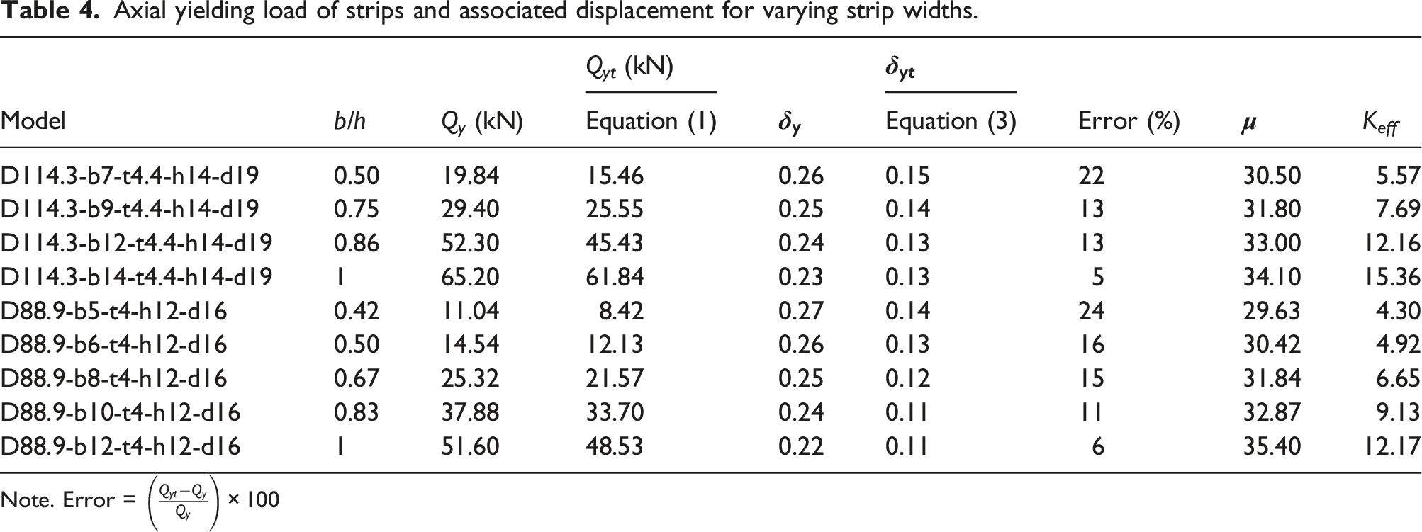
Note. Error =
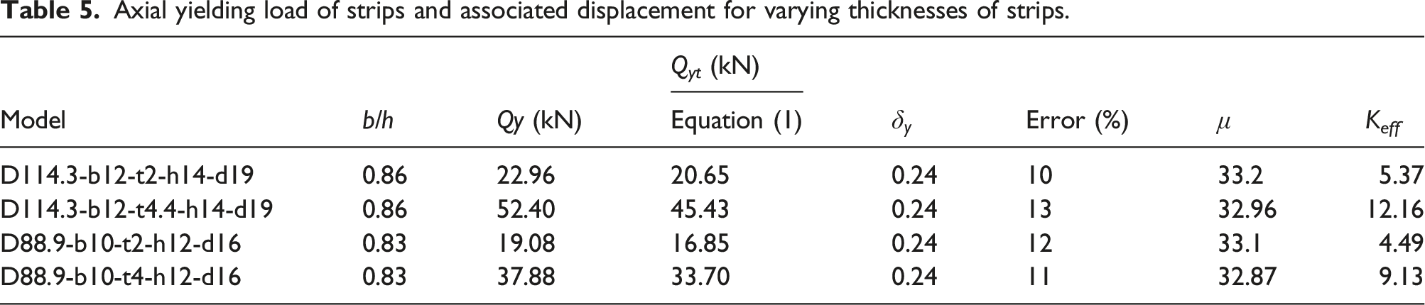
Axial yielding load of strips and associated displacement for varying thicknesses of strips.
Axial yielding load of strips and associated displacement for varying diameters of the slotted holes.

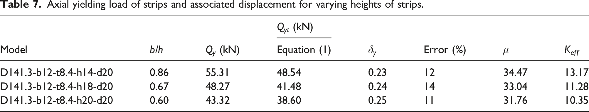
Axial yielding load of strips and associated displacement for varying heights of strips.
Axial yielding load of strips and associated displacement for varying diameters of circular cross-section tube.
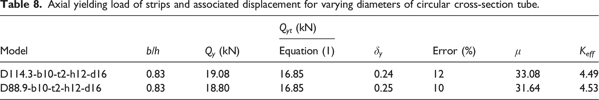
In Tables 4–8, axial yielding load for varying values of widths, thickness, diameters of the slotted holes, heights of strips, and diameters of the circular cross-section tubes obtained from FE analysis are compared with the predictions by equation (1). The results indicated that the predictions by equation (1) had a close correlation with the FE results and the predictions deviated from the FE analysis by a maximum value of 24%. The value of yielding load of the C-TTD dampers depended on the number of strips and their geometric characteristics i.e., the width, the thickness, the height of the strips and the yielding stress of the strip material. Therefore, C-TTD dampers with proper dimensions can be employed for the seismic retrofitting of the structures.
Numerical analysis of multi-storey buildings with C-TTD dampers
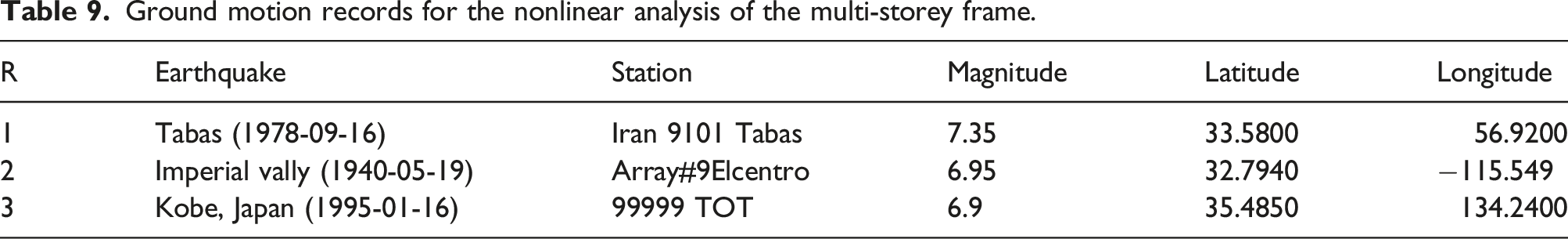
Ground motion records for the nonlinear analysis of the multi-storey frame.
The plan view of the designed buildings is shown in Figure 12. The typical storey height of the buildings was 3.20 m and the span of the beams was 4 m. The buildings were designed for the p-delta effect and had a dead load of 500 kg/m2 for all stories, and a live load of 200 kg/m2 for all floors except for the roof, which had a live load equal to 150 kg/m2, according to the Iranian National Building Code (Divisions 6 and 10). Two structural systems were considered for the seismic design of the building, including (1) a steel moment frame and (2) the same steel moment frame that was equipped with a system of C-TTD dampers. The pinned supports at the locations of the connections to the dampers were designed according to FEMA 356 (see Figure 12(b)). The C-TTD damper was modelled using multi-linear plastic link elements. The stiffness, yielding load, and displacement associated with the yielding load were modelled in the axial direction of the damper (U1 herein). The modelled dampers were in the original scale (proportional to the dimensions of the modelled structure) and had larger axial displacement capability when compared to the tested C-TTD damper, which was constructed in small size due to laboratory limitations. Therefore, the hysteresis diagrams of the dampers (axial load-displacement relationships) obtained from the FE analysis using ABAQUS were used to model the energy dissipation characteristics of the damper (Figure 13). Dampers are installed diagonally in the frame, with the deformation of the damper depending on the angle between the damper as a diagonal member and the beam placed horizontally in the frame. The damper hysteresis diagram for each storey in the numerical model is defined as a two-liner curve with no displacement limitation, according to Figure 14. The stiffness and yielding strength of the dampers were reduced from the first storey to the top storey to avoid a soft storey collapse. The optimum values for the stiffness and yielding strength were designed based on the minimum base shear load and the minimum relative displacement of the floors using a trial-and-error method (see Table 10). Structural model of 8-storey building. (a) Isometric view (b) Front view. Axial load-displacement relationship of top stories obtained from the finite element analysis using ABAQUS. (a) 4-storey (b) 8-storey (c) 15-storey. Definition of axial load-displacement relationship of dampers in numerical analysis of structures (top storey of 15-storey structures). Axial yielding load of dampers for various stories.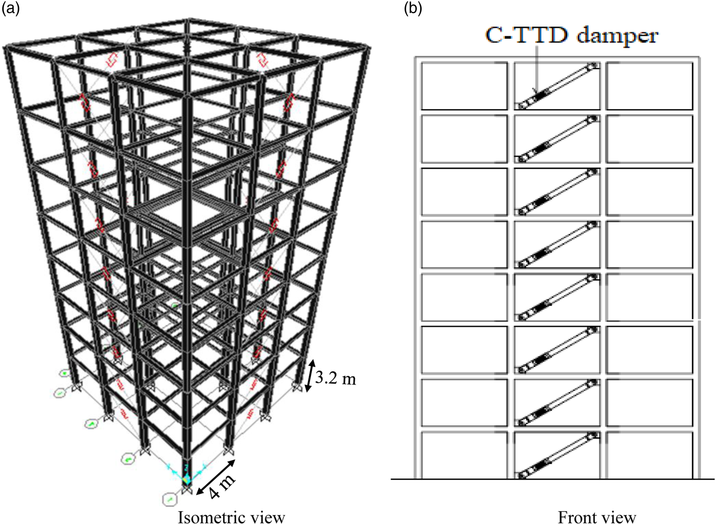


In Figure 15, the maximum inter-storey drift ratios (relative translational displacement between two consecutive floors divided by the storey height) for the steel moment frames with and without dampers when the buildings (4-storey, 8-storey, and 15-storey) were subjected to various earthquake scenarios are compared. The results showed that the inter-storey drift for the frame equipped with the damper was significantly smaller than the counterpart frame without the damper. The value of inter-storey drift for the 4-storey structure equipped with dampers ranged from 8% to 55% of the 4-storey structure without a damper. For the 8-storey structure inter-storey, this value ranged from 26% to 51%, and for the 15-storey structure, this value ranged from 33% to 49%. The inter-storey drift ratio of the bottom stories for the structures with and without dampers, when analysed for the Kobe earthquake, were similar, with this behaviour depending on the properties of the ground motion. Comparison of drift ratios in the stories under earthquakes. (a) Tabas earthquake, 4-storey; Tabas earthquake, 8-storey; Tabas earthquake, 15-storey (b) El Centro earthquake, 4-storey; El Centro earthquake, 8-storey; El Centro earthquake, 15-storey (c) Kobe earthquake, 4-storey; Kobe earthquake, 8-storey; Kobe earthquake, 15-storey.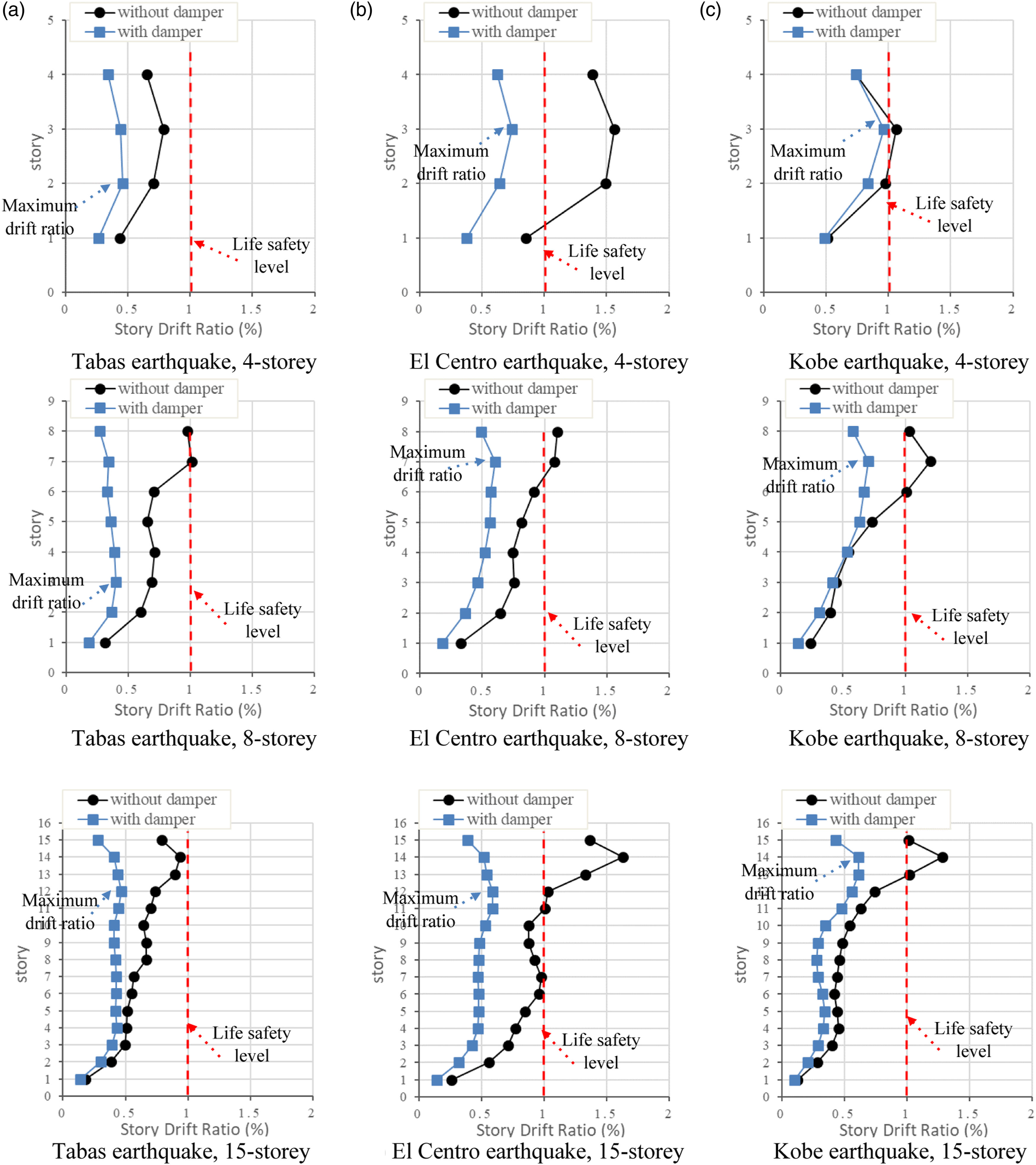
The maximum inter-storey drift ratio of the 4-storey, 8-storey and 15-storey buildings equipped with C-TTD dampers were 0.45, 0.40 and 0.47 for the Tabas earthquake, 0.74, 0.6 and 0.59 for the El Centro earthquake, and 0.95, 0.7 and 0.61 for the Kobe earthquake, respectively. These values were smaller than the life safety limit state (equal to 1.0% of the storey height), according to FEMA 356, indicating that C-TTD dampers can be employed for seismic retrofit of the existing structures.
Load-inter-storey drift responses of damper (The non-dimensionalized deformation capacity of slit dampers) under the Kobe earthquake in the storeys with maximum inter-storey drift ratio were extracted, as shown in Figure 16. The ductility value for C-TTD damper in these storeys of 4-storey, 8-storey and 15-storey buildings were 47.7, 35.43 and 25.4 respectively. Load-inter-storey drift responses. (a) 4-storey (b) 8-storey (c) 15-storey.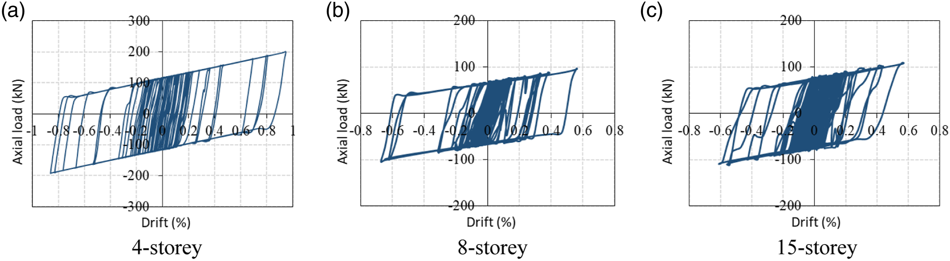
Comparison of maximum base shear load in multi-storey structure without and with circular tube-in-tube dampers.

In Figure 17, the internal and the absorbed energy have been shown for the multi-storey buildings when subjected to the three scaled earthquakes. The input and the absorbed energy in multi-storey buildings under earthquakes. (a) Tabas earthquake, 4-storey; Tabas earthquake, 8-storey; Tabas earthquake, 15-storey (b) El Centro earthquake, 4-storey; El Centro earthquake, 8-storey; El Centro earthquake, 15-storey (c) Kobe earthquake, 4-storey; Kobe earthquake, 8-storey; Kobe earthquake, 15-storey.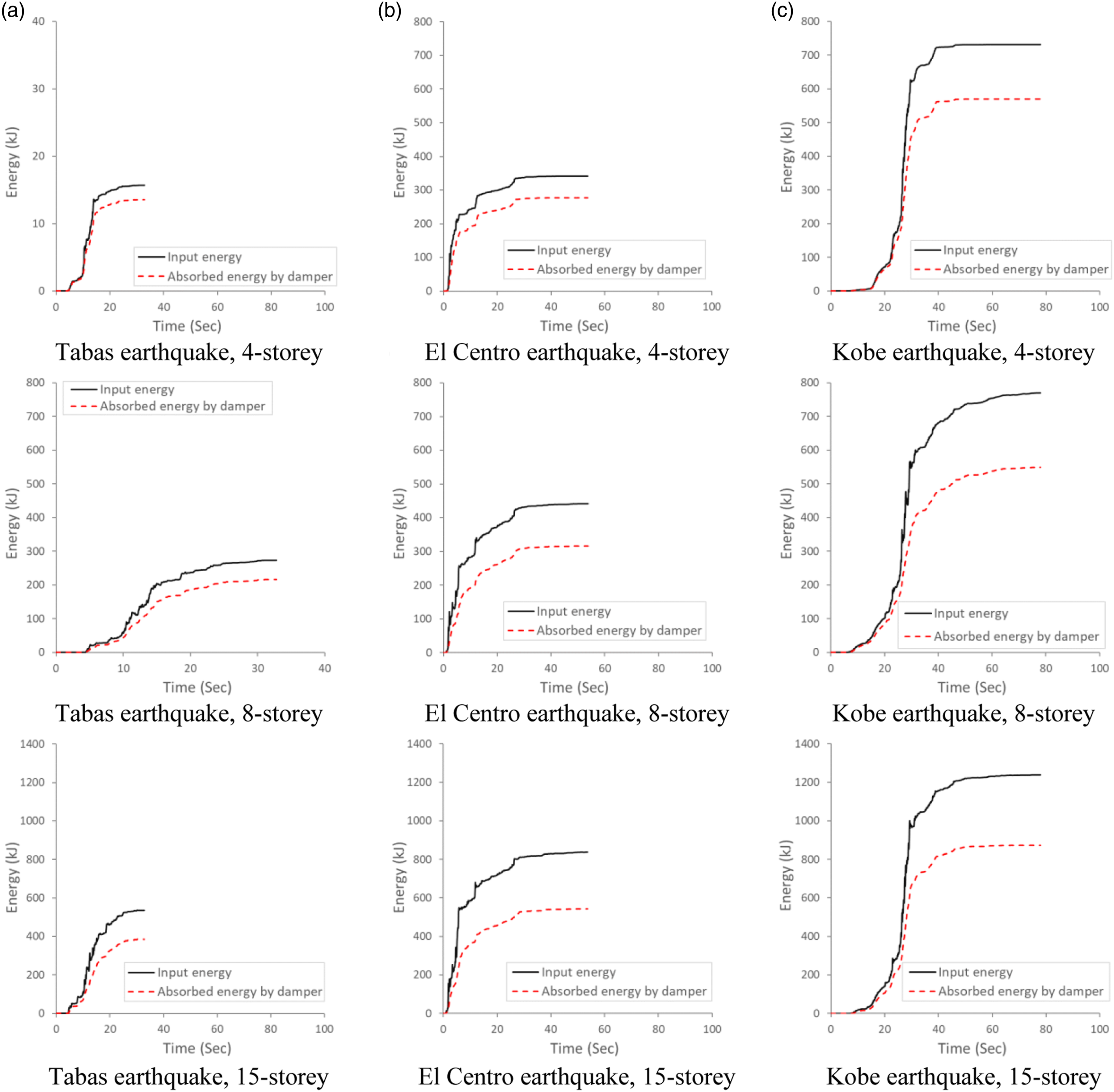
Comparison of maximum input energy and absorbed energy by dampers in structures without and with circular tube-in-tube damper.
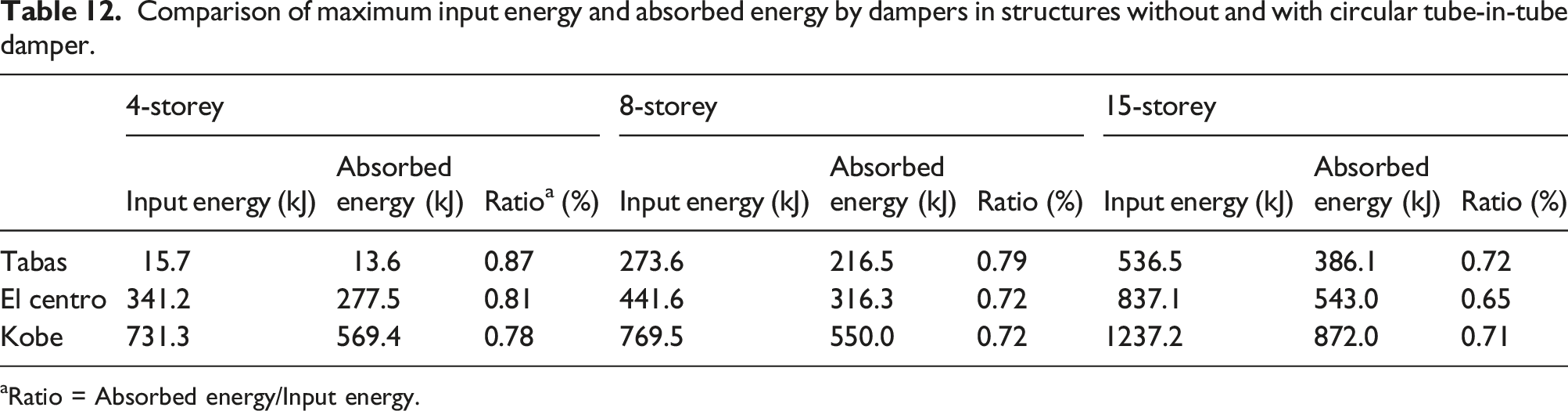
aRatio = Absorbed energy/Input energy.
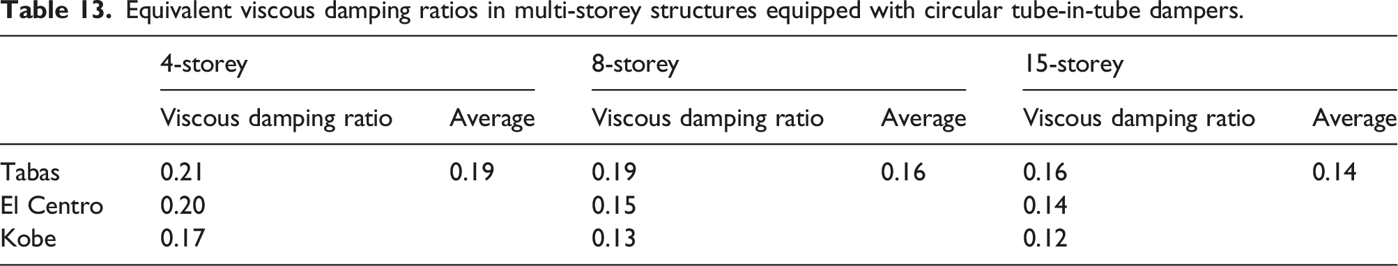
Equivalent viscous damping ratios in multi-storey structures equipped with circular tube-in-tube dampers.
Future research plan
While TTD dampers proposed by Benavent-Climent were flat, C-TTD dampers proposed in the current study reported herein were curved. Although a series of parametric studies were performed in Parametric study, a comprehensive parametric study is required to offer an equation to predict the strength and stiffness evaluation of the newly proposed C-TTD dampers.
In the study reported herein, three earthquakes were selected for studying the seismic response of steel frame structures equipped with C-TTD dampers. For future research studies, it is recommended the seismic excitations be selected according to the design seismic spectrum of a seismic design code to arrive at more convincing conclusions.
The response of structures equipped with C-TTD dampers will then be different from the structural response reported earlier in Numerical analysis of multi-storey buildings with C-TTD dampers.
Conclusion
In the reported study herein, a new brace-type slit damper called ‘Circular Tube-in-Tube Damper’ (C-TTD) was proposed for improving the seismic resilience of the structures. C-TTD dampers are composed of two steel solid cylinders and one circular cross-section tube equipped with slotted holes, with the components connected using bolts. C-TTD dampers offer the advantages of easier inspection and replacement of the damaged components when compared to conventional TTD, which require complete replacement of the entire damper if a component is damaged. The effect of strip and slit dimensions on the axial yielding capacity of the C-TTD dampers were investigated using FE modelling. Additionally, the seismic performance characteristics of 4-storey, 8-storey and 15-storey steel frame structures that were equipped with C-TTD dampers were analysed for varying earthquake ground motions and the results were compared with the response of counterpart buildings with no dampers. Conclusions drawn are listed as follows: 1. Theoretical models that were developed by Benavent-Climent (Benavent-Climent, 2010) for predicting the axial yielding capacity of the steel slit dampers were found to be in good agreement with the yielding capacity of C-TTD dampers and therefore can be used for the design of C-TTD dampers. 2. By equipping the steel frame structures with C-TTD dampers the inter-storey drift of the stories decreased by a range of 8%–55%, and the structures remained elastic by decreasing the life safety limit state of the storeys below 1.0% of the storey height. 3. The numerical analysis showed that C-TTD dampers absorbed 70%–80% of the vibration energy of the structures. The average viscous damping ratio for a 4-storey structure equipped with C-TTD dampers was 19%, for an 8-storey structure was 16% and for 15- storey structure was 14%. 4. The base shear load in steel frame structures in earthquake scenarios decreased by a range of 27%–35% when C-TTD dampers were equipped.
In the reported study herein, a single C-TTD damper geometry was studied, and therefore these findings are not yet conclusive, and further experimental and numerical studies must be carried out to validate the results and the applicability of the developed equation by Benavent-Climent (Benavent-Climent, 2010) for other sizes of C-TTD dampers.
Footnotes
Declaration of conflicting interests
The author(s) declared no potential conflicts of interest with respect to the research, authorship, and/or publication of this article.
Funding
The author(s) received no financial support for the research, authorship, and/or publication of this article.