



Abstract
This paper first discusses the causes of damage to buildings and structures due to various types of winds including daily winds and some extremely strong winds. Regarding devastating wind-induced disasters due to tropical cyclones (TC), the importance of combined effects of wind and water hazards is emphasized. It also points out human errors hidden in damage scenarios, especially for large buildings. The importance of cladding/component design, the significance of debris impacts, and the effects of sudden changes in internal pressures are also emphasized. The design principles for buildings and structures are also examined, and the crucial differences among building performances against TCs and severe local storms such as tornadoes and downbursts are discussed. Design load levels for temporary buildings including scaffoldings and construction offices and for conditional buildings and structures including cranes, movable roofs and so on are also discussed. Next, design issues of tornado effects on highly important and highly influential buildings such as nuclear power plants are discussed. Finally, to cope with the future increasing trend of wind-related disasters, the importance of decarbonization and full-scale storm simulators are emphasized.
Damage to buildings and structures due to winds
Typical wind pressure patterns acting on a low-rise building
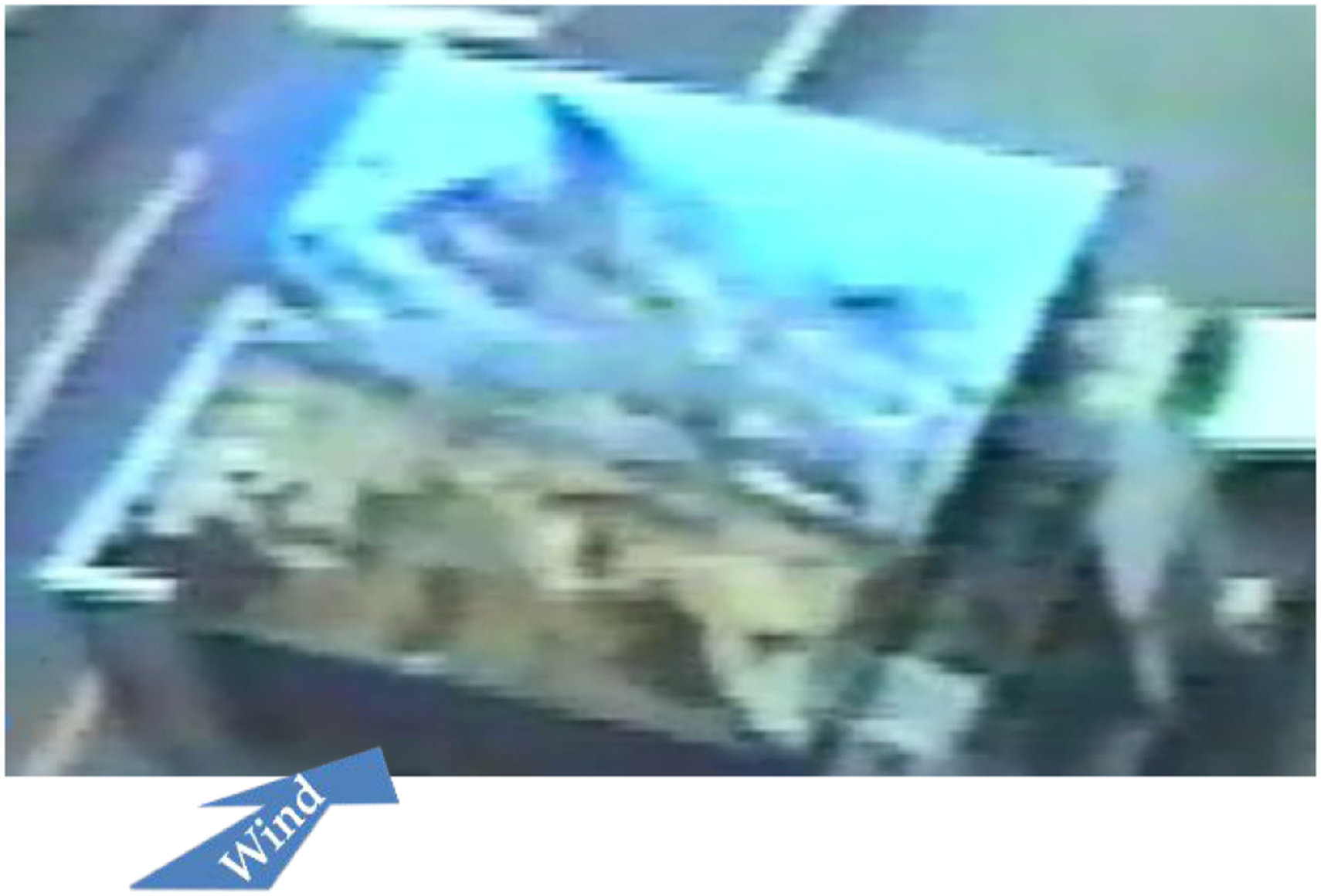
There are various types of wind climates that cause damage to buildings and structures. These will be discussed in the next section. As the majority of damaged buildings in areas affected by tropical cyclones (TCs) or tornadoes are low-rise buildings, it might be useful to show typical wind pressure distributions acting on the surfaces of a low-rise building. Figure 1(a) shows instantaneous pressure distributions acting on the surfaces of a low-rise building model obtained by the simultaneous multi-channel pressure measurement system (SMPMS) in a wind tunnel. Red indicates positive pressures and blue indicates negative pressures. Positive pressures act on the windward wall only, and negative pressures act on the roof surface, side walls and leeward wall. Thus, 90% of the external surface area of the building is subjected to negative pressure. Especially, the area near the roof’s leading edge is subjected to very large negative pressures that can cause roof failures. Large negative pressures also appear near the leading corner of the side faces. The term “wind pressure” is commonly used, so it is said that building surfaces feel “pressurizing” actions. Negative pressures cause “tearing-off” actions or “sucking-up” actions, as shown in Figures 1 and 2, while positive pressures are limited to the windward area and do not suffer these effects. Because of the resultant force of the positive pressure on the windward wall and the negative pressure on the leeward wall, along-wind force (drag force) acts on the building. More importantly, a large up-lift force always acts on a low-rise building due to the negative pressures on the roof surface, and the roof or the entire building tends to be lifted up. Thus, the building and its roof can be lifted and blown off in the downstream direction, even in horizontal straight winds. Wind pressure distributions on surfaces of a low-rise building. (a) Instantaneous wind pressure coefficients (Red: Positive, Blue: Negative) obtained by wind tunnel test (RISC, 2000) (b) Schematic view of pressure distribution in vertical section with opening in windward wall (Tamura et al., 2018). Tearing-off action caused by high negative pressure near leading edge on rectangular flat roof (Typhoon Mireille, 1991; Courtesy of Mr M. Koga).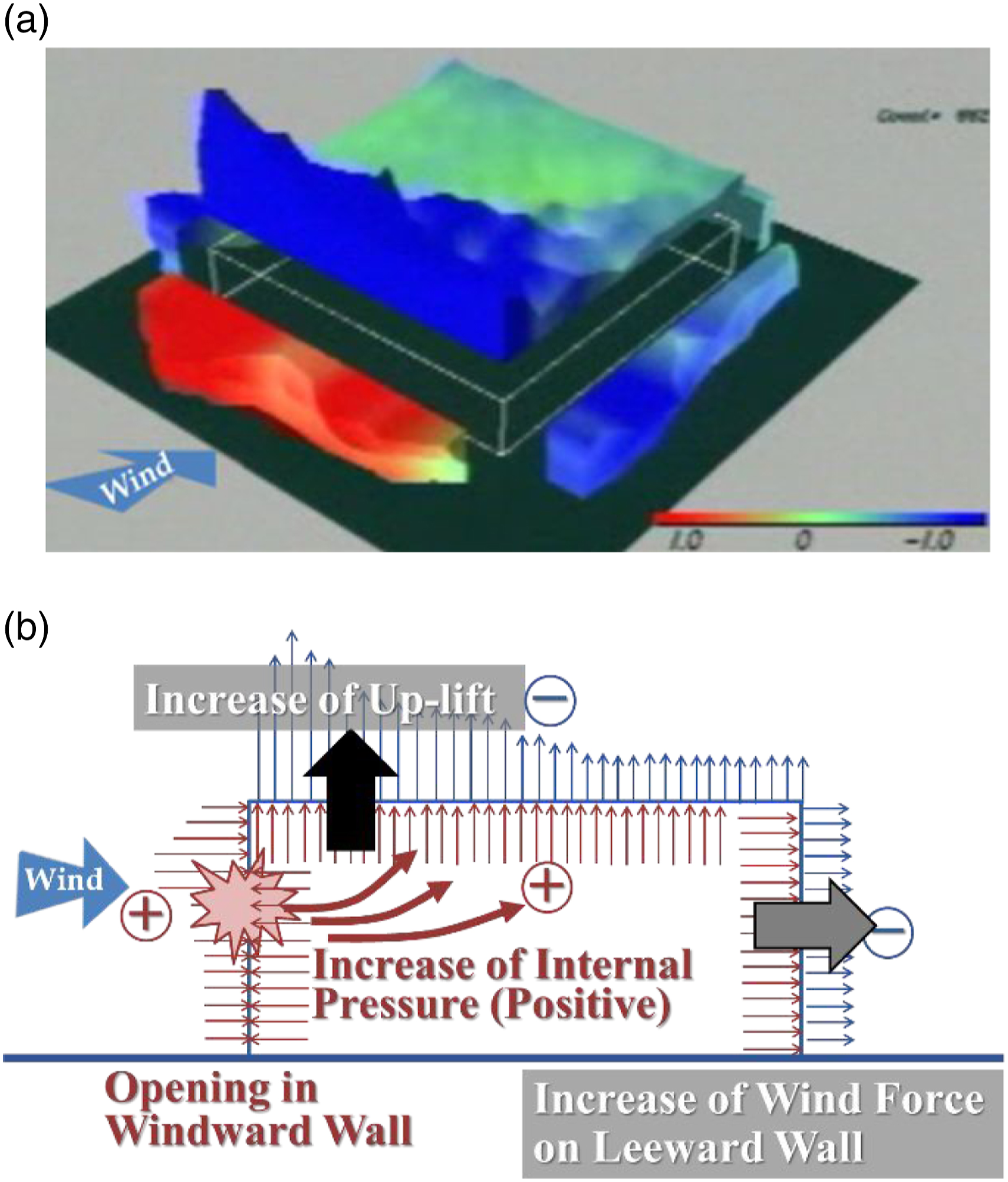
Another important aspect of wind action is shown in Figure 1(b). Once an opening is made in the windward wall by strong wind pressure or wind-borne debris, air enters the interior, and the internal pressure suddenly shifts to a positive value similar to the external wind pressure at the opening, and the resultant uplift force acting on the roof significantly increases, especially near the roof’s leading edge. The resultant forces acting on the leeward wall and the side walls also increase, and damage or blow-off of the roof and walls progressively result.
Damage due to strong winds: Tropical cyclones and severe local storms including tornadoes
The large loads due to strong winds can be the main reason of the damage to buildings and structures. However, the wind-borne debris and the combined effects of wind and water hazards also account for damage.
Effects of wind pressures and debris impacts
Extreme TCs cause significant roof damage due to high negative pressures. This creates a lot of air-borne debris which can also cause significant cladding damage. This debris is mainly produced by damaged parts of buildings as well as ground obstacles such as gravel and trees. The flying speed of wind-borne debris can converge to the background wind speed, but it normally impacts downstream buildings or ground before reaching this speed (Holmes et al., 2006a, 2006b; Lin et al., 2006; Tachikawa, 1983). We should note that debris impacts are more significant than wind pressures. This might be easily understood by considering the fact that the mass density of wind-borne debris is much higher than that of air density. The majority of wind-induced building damage is likely caused or initiated by wind-borne debris impacts.
Another typical example of strong wind is a tornado. The meteorological environment generating tornadoes are not simple, but in many cases they are generated under developed cumulonimbus called ‘supercell’ (Niino, 2007). Their wind speed can be higher than 100 m/s in extreme cases, and they can cause intense and destructive damage to buildings and structures. In tornadoes, debris can be conveyed to far away locations by the updraft component of the tornado wind, and the effects of debris impacts are more significant than for TCs. Overall damage footprints due to tornadoes tend to show line-like patterns, and local rotational flow patterns can sometimes be seen, as shown in Figure 3. Damage to fence due to swirl flow (Yancheng Tornado, China, 23 June 2016).
Under similar meteorological conditions to tornado genesis, downbursts can occur with the downdraft part of a supercell. The terminology ‘thunderstorm’ is also used to mean ‘downburst’, but we consistently use downburst in this paper. Because of the spread of flow at ground level, damage often shows radial patterns.
Combined effects of wind and water hazards
The devastating Cyclone Bhola made landfall in East Pakistan (current Bangladesh) on 12 November 1970, and killed 300,000–500,000 people. The exact number of fatalities and missing was not officially reported. The maximum recorded 1min mean wind speed was 57 m/s and the lowest pressure was 966 hPa, and the economic loss was estimated at 0.46 B USD. For more detailed information, please refer to other sources, e.g., India Weather Review (1970), Frank and Husain (1971), Schwerdt (1971), and Biswas and Daly (2021). The huge number of fatalities was due to storm surge, and the combined effects of wind and water hazards should be noted for TCs. Hot spots of fatalities due to natural hazards such as TCs are in developing countries, especially in South Asia (Tamura et al., 2017).
Incidentally, in the US, Hurricane Katrina made landfall on Florida on August 25, and a second landfall on Louisiana on 29 August 2005. The lowest pressure was 902 hPa, and the maximum 1min mean wind speed was reported at 78 m/s. However, the maximum wind speeds recorded were 51 m/s (3s gust) and 42 m/s (mean) (Sakakibara et al., 2006). Fatalities and missing were reported as 2541, and the estimated economic losses were more than 100B USD. Thus, even in a developed country like the US, a lot of people were killed by this TC. The majority of fatalities and missing were due to water hazards caused by storm surge and floods. Many people evacuated to Louisiana Dome, but roof cladding damage created unpleasant and difficult environments.
Cyclone Nargis attacked the bay area of Myanmar on May 2 and 3, 2008. The maximum peak gust was reported at 60 m/s and fatalities and missing numbered 138,366, and the economic loss was estimated at 10B USD (Zaw, 2009). Significant human losses are continuing, due to the combined effects of wind and water hazards.
More recently, Typhoon Haiyan attacked the Philippines on 8 November 2013. Fatalities and missing numbered 7986 (NDRRMC, 2014). The lowest pressure recorded was 895hPa, the maximum observed 3s gust was 57 m/s, and the maximum estimated 3s gust was 78 m/s. The huge number of human losses were again caused by storm surge, and the combined effects of wind and water hazards were a key issue.
We should note that devastating TCs generally cause not only wind hazards but also severe water hazards. Water hazards are caused by severe precipitations and storm surges. Thus, we should consider the combined effects of wind and water hazards caused by TCs. For evacuation timing, we should also consider both wind and water effects, including the significance of water speed. As water mass is almost 1000 times larger than air mass, forces caused by water flow are much higher than we imagine. A water speed of 3 m/s is equivalent to a wind speed of 85 m/s, which is almost the same as a severe tornado. A wind speed of 30 m/s makes it hard to stand or walk, and this is almost equivalent to a water speed of 1 m/s. Especially for storm surge or bank breakage, the water speed issue should be carefully considered.
Damage due to moderate and low winds
Damage to buildings and structures is not necessarily caused by a strong wind. If the ‘resistance’ or ‘performance’ of a building is not sufficient, it can be damaged even in low ‘load’ or ‘action’.
Gravity winds, dust devils, and blasts
Figure 4 shows the collapse of a steel framed temporary tent structure constructed for an event in Cape Town, South Africa, on 8 August 2003. The reason for this collapse was determined to be ‘gravity wind’. The first and second presidents of South Africa, Nelson Mandela and Thabo Mbeki, were on stage at the time (Goliger, 2006). The downburst described in the previous section was also affected by gravity force, but it was meteorologically generated. However, ‘gravity wind’ is mainly due to topographic effects. Once the cold and heavy air at the top of a mountain moves and starts to slide downhill, the air is accelerated by gravity force, and its speed can reach a level that can destroy some structures. This is also called ‘katabatic wind’. The wind speed wasn’t so high, presumably 10 m/s–15 m/s, but the structure collapsed. Figure 4(b) shows the bottom end of a column of the supporting frame, which has four straddling arms and was not anchored. As can be seen, the structural resistance was insufficient. Collapse of temporary tent structure due to gravity wind (katabatic wind) in Cape Town, South Africa, 8 August 2003 (Goliger, 2006) (a) Collapse of tent structure (b) Bottom end of column.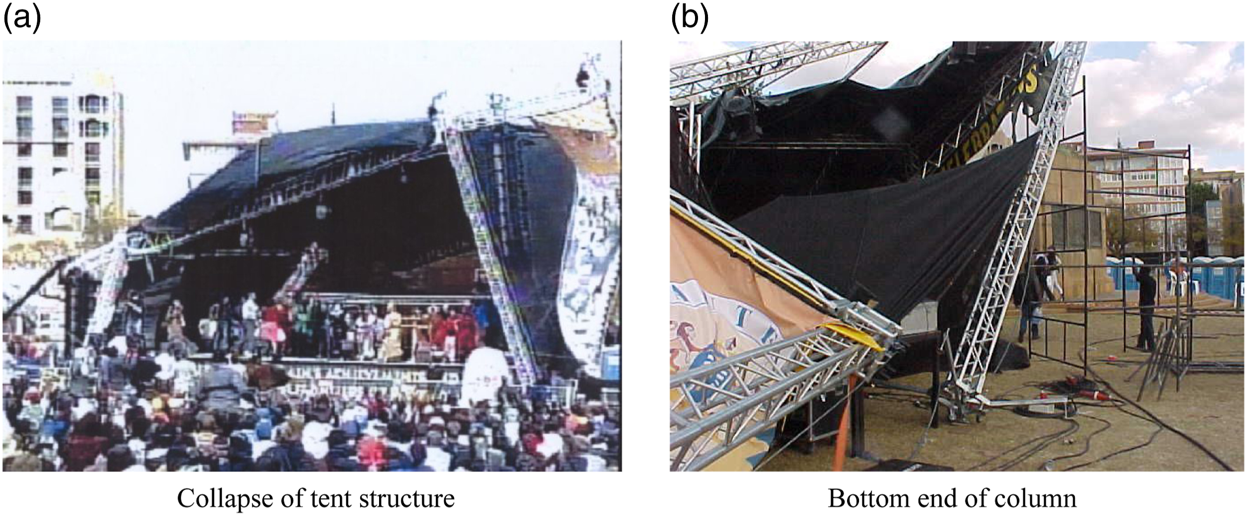
On sunny days, small funnel-like vortexes can be observed over open ground such as school playgrounds, deserts and so on. These are called “dust devils”. Air above the ground is heated by the sun, causing an updraft flow that picks up shear flow near the ground creating a vertical vortex. The shape is like a small tornado, but the sky is clear and there is no cumulonimbus, so it is quite different from a tornado. The wind speed is not high, but can occasionally destroy light-weight structures such as tents.
Underestimation of uplift force
Wind-induced accidents have been reported at wind speeds of only around 10 m/s–20 m/s. Figure 5 shows an accident that occurred during an athletic meet. Around five people were sitting on an air-mat intending to hold it onto the ground by their combined weights. However, the uplift force acting on the upper surface of the mat lifted it up and blew it away. The people who were sitting on the mat were also lifted up, and one of them crashed to the ground from around 7 m high. People generally underestimate the uplift force acting on such a mat, which has a similar shape to the low-rise building shown in Figure 1. If the instantaneous wind speed, say 3s-gust, exceeded 20 m/s and the air-mat had a 7 m × 7 m plan, the uplift force can easily exceed 1 ton, which is much larger than the people’s total weight. Such misunderstanding of the significance of the lift force acting on bluff bodies can injure or kill people. Blow-away and overturning of air-mat due to a blast (Courtesy of TV Asahi).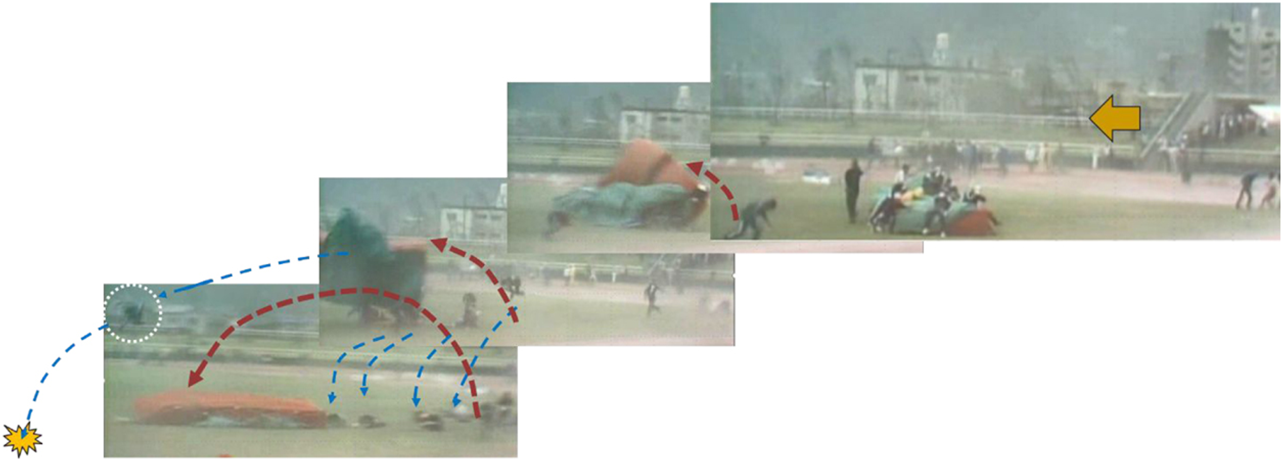
Bounce houses often cause accidents in moderate winds exceeding around 10 m/s (3s gust) (Yoshida and Tamura, 2009). There are many different types of inflatable amusement products or bounce houses, and they are utilized at various places around the world (Figure 6). Considering wind forces including significant uplift forces acting on them, appropriate anchoring is required. However, the majority are for temporary use and they are placed on the ground or floor, and connected to small sand bags or water tanks. Like the air-mat shown in Figure 5, the uplift force can be very significant even at moderate wind speeds of 10 m/s–20 m/s, and they can be easily lifted and blown away. As a result, many kids and babies are injured every year around the world. If it is difficult to provide sufficient anchoring, operators should strictly follow manuals or regulations that specify a safe operation system including a wind speed monitoring method, service suspension wind speed, and so on. Knowledge dissemination about uplift force is also urgently required. Examples of inflatable amusement products (Yoshida and Tamura, 2009). (a) Slider type (b) House type.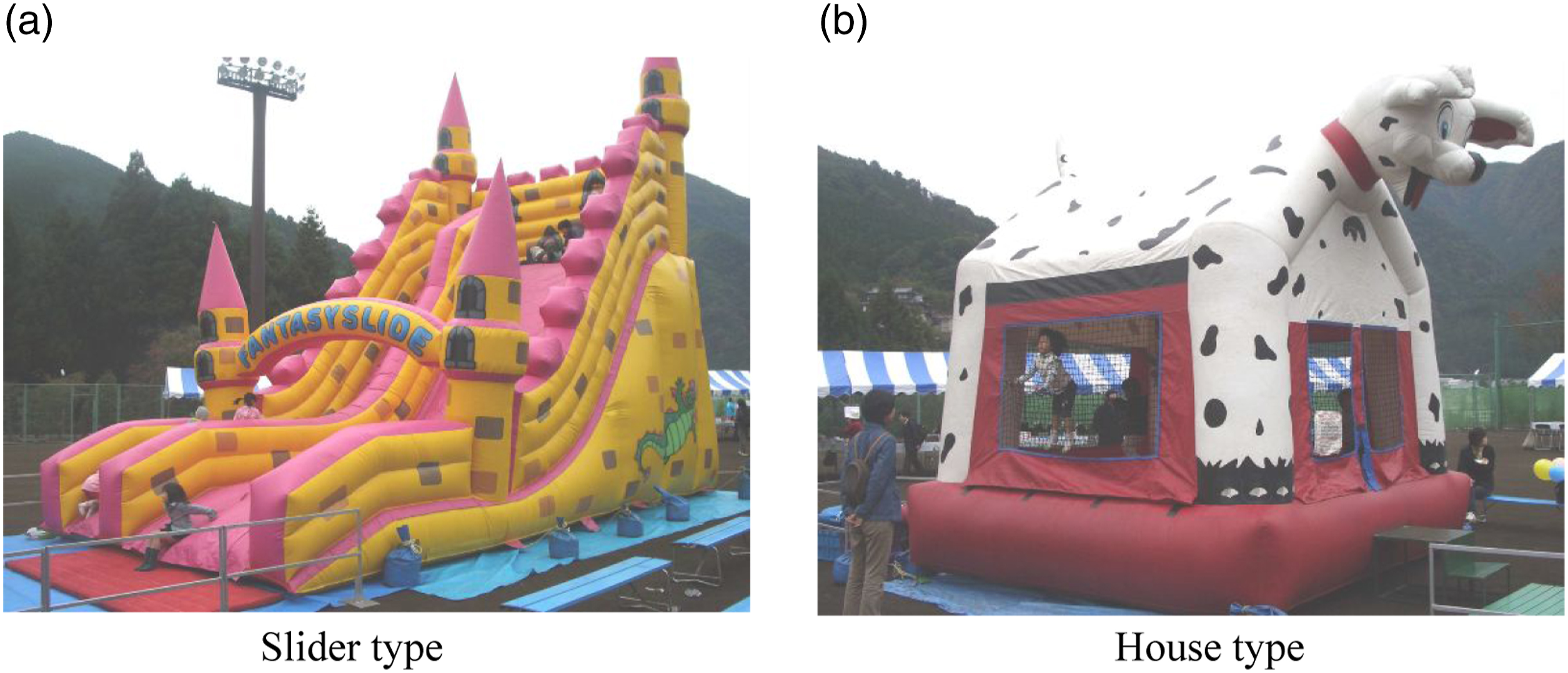
Vortex-induced vibration and others
Another example of damage and accidents due to low-level wind speed is vortex-induced vibrations (VIV) of structures and elements of structures.
Figure 7 shows vortex-induced vibrations of an 11 m-span, 216.3 mm-diameter steel pipe beam and snap shots for 0.1 s (= T
1
/2: a half the fundamental natural period T
1
= 0.2 s). The fundamental natural frequency of the beam was 5 Hz, and VIVs were observed in daily winds from 4 m/s–10 m/s (30 s-mean). The structure was composed of 64 beams, and violent vibrations due to vortex resonance were observed almost every day. Many of the beams were damaged due to the fatigue effect 6 months after construction (Tamura, 1980). VIVs often occur to not only such space frame members, but also illumination poles, traffic signal facilities, transmission towers, chimneys, and so on under moderate or low wind speed conditions. Vortex-induced vibration of a steel beam (11 m span, 216 mm diameter) under mean wind speed ≈ 5 m/s (Tamura, 1980): (a) Sequential snap shots during 0.1 s (≈ T
1
/2, T
1
: fundamental natural period of a beam) (b) Fluctuating strain of a beam showing steady state resonant excitation.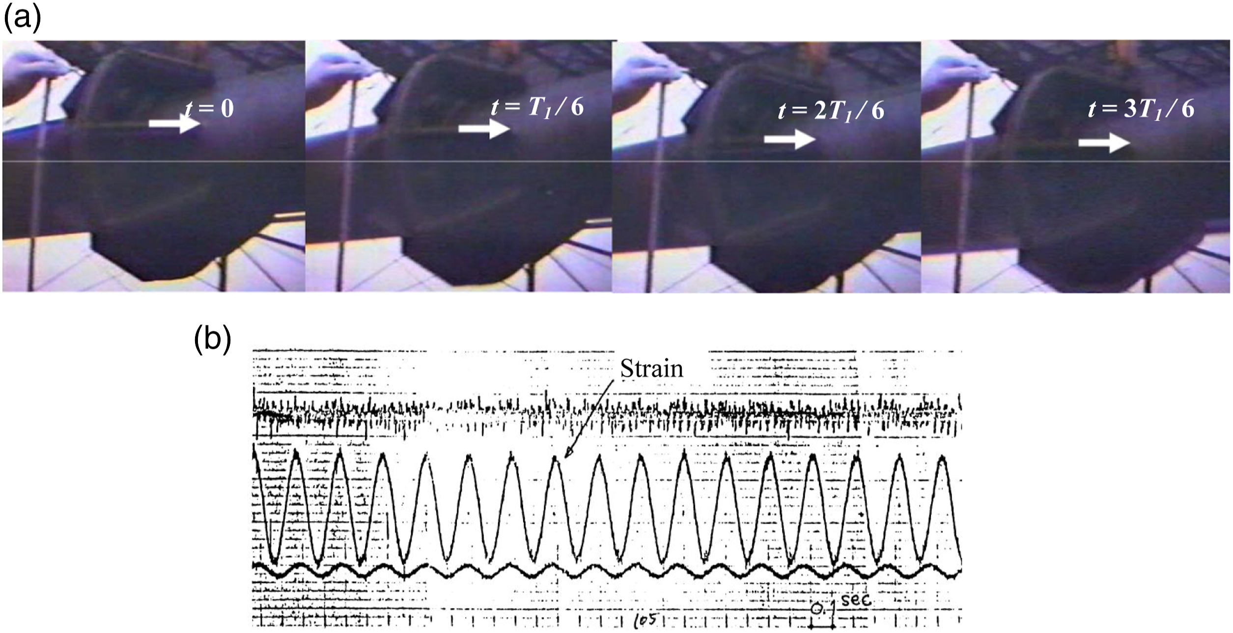
Stay cables of cable-stayed bridges undergo rain-wind-induced vibrations under moderate winds, e.g., 10 m/s–20 m/s, and flexible and light weight structures undergo some other types of vibrations such as galloping and torsional flutter. Thus, we should note that wind-induced damage is not necessarily due to strong winds, and care should be taken even for moderate and low wind conditions depending upon the target buildings and structures.
Human errors hidden in damage scenario
Careful checks of buildings and structures damaged by winds suggest various kinds of human errors hidden in the damage scenarios, and some examples are introduced in this section.
Lack of knowledge of membrane design
Figure 8 shows a soccer stadium in Chejudo Island, Korea, whose membrane roof members were broken on 31 August 2002, when Typhoon Rusa attacked the site. The wind speed recorded at the nearest meteorological station in Chejudo Island was not high, i.e., the maximum 10 min mean V
10min
= 14.2 m/s and 3s-gust V
3s
= 28.7 m/s (AIK, 2002). The possibility of a severe local storm (SLS) such as downburst or tornado was suspected. Damage to membrane roof of Seogwipo Soccer Stadium, Chejudo, Korea, 31 August 2002: (a) Damage to membrane roof (b) Renewed roof.
As is well known, the most important matter in the design of membrane structures is to achieve uniform distributions of tensile stress and strain. However, Figure 8(a) shows pointed peaks on the roof surface, which clearly suggests stress and strain concentrations. Patches are prohibited in construction of membrane structures, because they might weaken the strength of the membrane roof system. If the designer of this stadium had sufficient knowledge of the membrane structures, this damage might have been prevented. Thus, one reason for this damage might be attributed to ‘human error’. Since this event, the stadium has been reconstructed as shown in Figure 8(b), and a moderate roof shape was adopted to realize uniform distributions of stress and strain.
No performance check of roofing systems
The steel roofing system of the large structure of the RIKEN SPring-8 Center (RSC) was damaged by two typhoons: Chaba (30 August 2004) and Songda (7 September 2004). The plan of the building is donut-shaped, with an approximately 1500 m circumference and a 30 m width as shown in Figure 9. Damage to roofing system of RIKEN SPring-8 Center (RSC) due to Typhoon Chaba (30 August 2004) and Typhoon Songda (7 September 2004) (Tamura et al., 2005): (a) Damaged parts of roof (b) Tear-off of roof plates near leading edge (c) Section of two-layer folded steel plate roofing (d) Section of bolt indicating fatigue damage.
The roofing system consists of two-layer folded steel plates with thermal insulating materials between them, and the trough and ridge lines of the folded plates are in the radial direction. The leading edges of the roof were damaged due to high negative pressures (see Figure 1) by the two typhoons. Measured wind speeds (3s gusts) at the site were less than 40 m/s and much less than the design wind speed. The damage was attributed to the fatigue effect on the bolts connecting the roofing system to the tight frames due to daily solar heating effects on the upper layer (Tamura et al., 2005). Nobody, including the structural designers, had confirmed the performance of the roofing system, in which the upper plates were believed to slide over each other. Nobody suspected the fatigue phenomena caused by daily deformations of the bolts due to solar heating without any scientific data. This should also be categorized as ‘human error’. The damage suggests the importance of performance evaluation and periodic maintenance of the cladding systems.
No consideration of dust accumulation and friction effects
Figure 10 shows roof damage to the 48.9 m-high 148 m-span Izumo Dome due to Typhoon Songda. The 0.8 mm thick Teflon-lined glass-fiber membrane roof is supported by an arch string structure with composite wooden members. To maintain V-shaped undulations on the roof surface, 52 mm-diameter outer cables were used. The maximum 3s-gust observed at the nearby fire station was 38.8 m/s, which was much less than the design wind speed. Damage to membrane member of Izumo Dome due to Tyhpoon Songda (Nishimura et al., 2005): (a) Inside view (b) Outside view.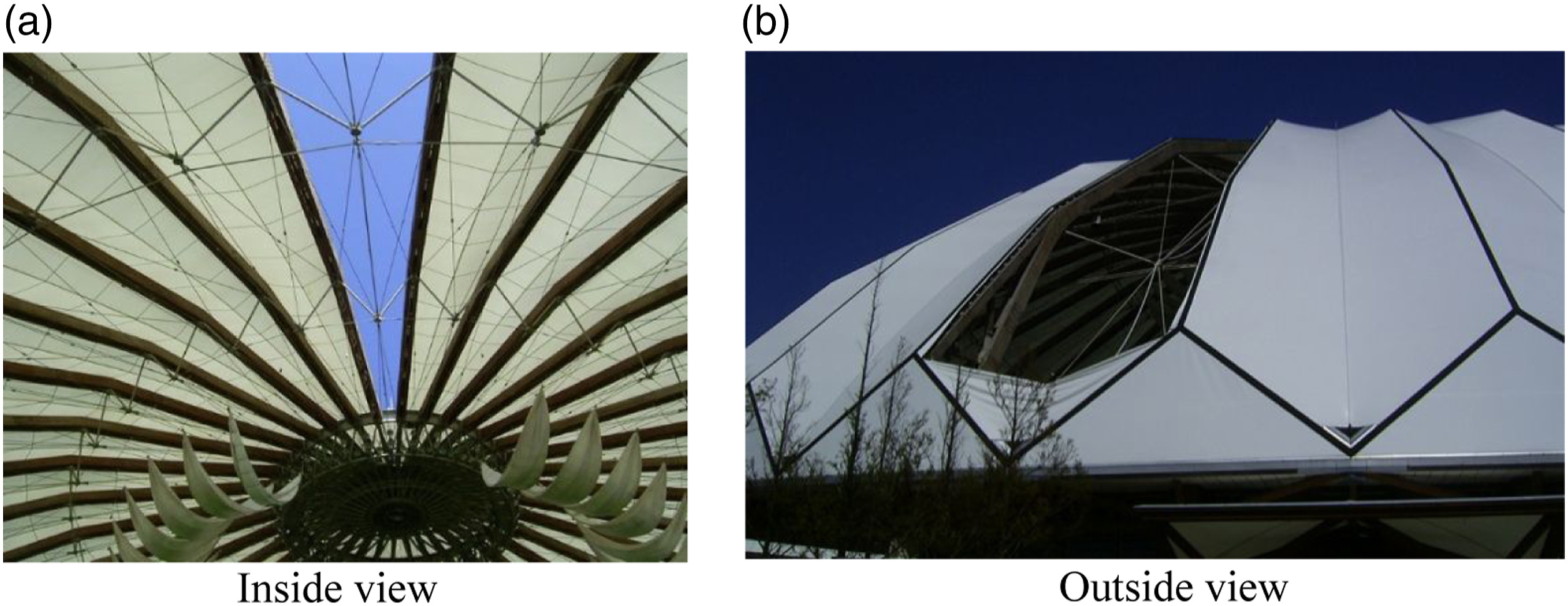
It was found that dust accumulated between the outer cables and the membrane members, and they rubbed each other due to daily ambient vibrations of the structure. Thus, the upper surface of the Teflon-lined membrane members had been damaged before the typhoon struck (Nishimura et al., 2005). This might also be categorized as ‘human error’.
Lack of knowledge about structural and aerodynamic behaviors
Figure 11 shows damage to a single-layered lattice dome of a coal yard in Hualian located on the eastern coast of Taiwan due to Typhoon Haitang (Cheng, 2014), which made landfall in Taiwan on 18 July 2005. As seen in the figure, the structure is an open-top single-layer lattice dome. Considering its size, it is too flexible, and the open top reduces the rigidity of the entire structure. In addition, the open roof reduces the back-pressure of the windward wall to a large negative value, and the resultant force acting on the windward wall becomes large. If the structural designer had enough knowledge about those aerodynamic and structural features of the dome, a different structural solution might have been proposed at the design stage (Cheng, 2014). Thus, this damage can be categorized as ‘human error’. Single-layered dome (Cheng, 2014): (a) Outside view (b) Inside view.
No consideration of aerodynamic effects of ventilating openings
Figure 12 shows the damage to the entire roof system of the Leyte Convention Center, Leyte, in the Philippines due to Typhoon Haiyan. Because of the large negative pressures acting near the leading edge of the roof shown in Figure 1(a), the roof beams were lifted and dropped to the ground, as shown in Figure 12(a). Unfortunately, many people were killed in this building, as it was assigned as a refuge. Failure of Leyte Convention Center, Palo, Leyte, the Philippines, due to Typhoon Haiyan, (Sanada et al., 2015): (a) Collapsed truss roof beams (b) Ventilating openings in windward wall.
Like the SPring-8 shown in Figure 9(b), the large negative pressures near the leading edge caused the damage, but there was also an apparent ‘human error’ in this case. As seen in Figure 12(b), there are many ventilation openings in the windward wall. These openings and jalousie windows are typical of buildings in warm and humid regions like the Philippines, and are necessary to save energy for air-conditioning. However, the effects of openings on internal pressures should be taken into account in the wind-resistant design of those buildings, which are different from general closed-type buildings. Special consideration of the phenomena shown in Figure 1(b) should be given, and careful evaluation of the internal pressure is required. If the structural designer had appropriately evaluated the lift force acting on the roof structure, there would have been a different result.
Importance of cladding and component design
Figure 13 shows damage to roof sheets of the EGS Contact Center, Palo, Leyte, in the Philippines due to Typhoon Haiyan. The damage was only to roof claddings and components. There was no serious damage to the main frames, as shown in Figure 13(a). However, as shown in Figure 13(c), the property inside the building was completely trampled down by strong winds and rain, and business continuity planning (BCP) could not be maintained. This was a deathblow to the building owner. Damage to EGS Contact Center, Palo, Leyte, the Philippines, due to Typhoon Haiyan (Sanada et al., 2015): (a) Damage to roof sheets (b) Trigger damage to windward window panes (c) Inside view.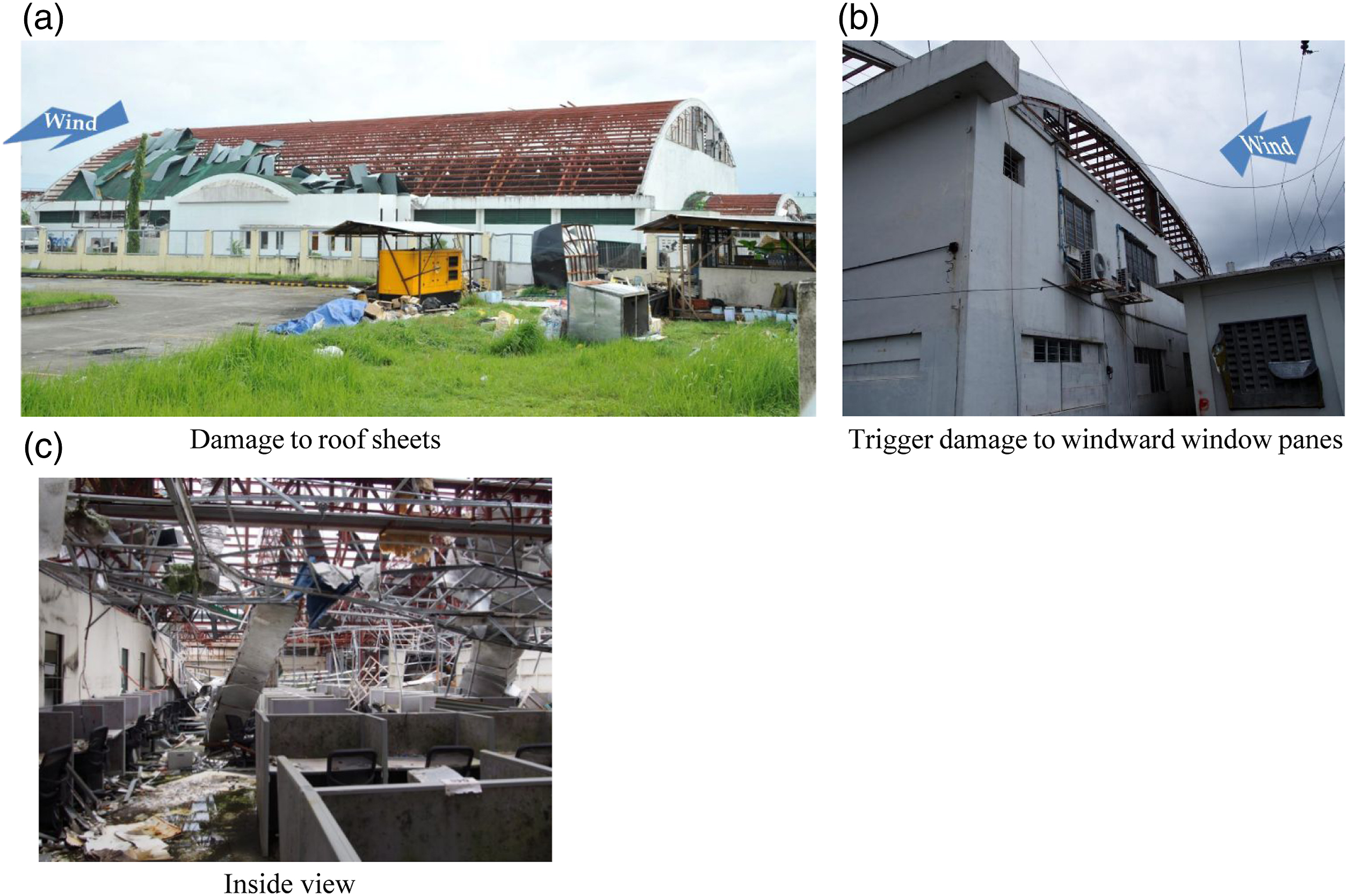
We should recognize the importance of cladding and component design, and we should note that ‘wind-resistant design’ is almost equal to ‘cladding/component design’. Incidentally, this complete loss of building property was triggered by breakage of window panes in the windward wall, as shown in Figure 13(b). It was not clear if the breakage was due to wind pressure or wind-borne debris. We should note the importance of cladding and component design including window panes.
Another example demonstrating the importance of cladding and component design is shown in Figure 14, which shows damage to the Vishakapatnam Airport Terminal Building in India due to Cyclone Hudhud, on 12 October 2014. Damage was also only to roof cladding sheets: the main frames suffered no damage. However, the inside of the building was similarly seriously damaged, and the building function was completely lost. Thus, the airport itself could not be efficiently used for immediate rescue and recovery activities. Damage to Vishakapatnam airport terminal building due to cyclone hudhud, India, on 12 October 2014 (courtesy of A. Mittal).
Impacts of wind-borne debris and damage chain
Figure 15 shows penetrating debris and marks in wooden walls due to tornadoes in Japan in 2006. Debris impacts and marks due to tornadoes in Japan: (a) F2 tornado in Nobeoka, Miyazaki, Japan (b) F3 tornado in Saroma, Hokkaido, Japan, on 7 November 2006, on 17 September 2006 (courtesy of Saroma-cho).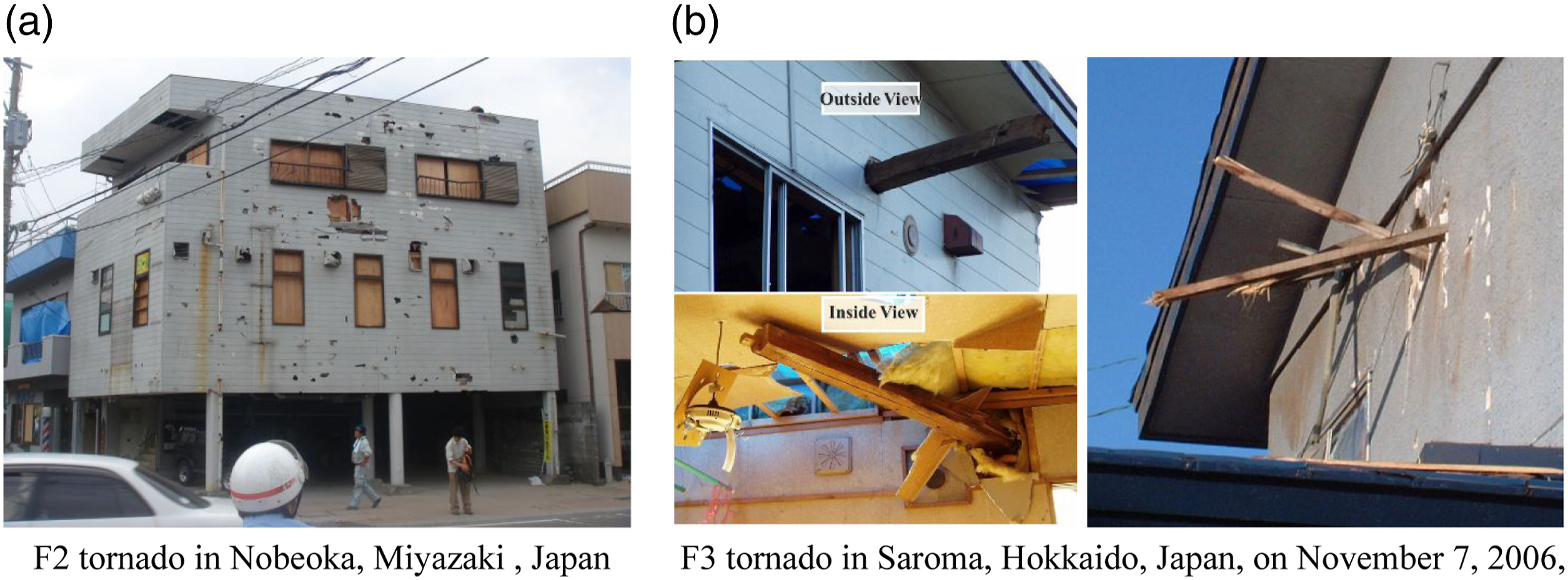
As mentioned in the previous section, debris impacts on buildings are significant in strong winds, so we need to protect buildings and structures, as well as people, from debris impacts. Debris impacts onto downstream buildings cause secondary damage. Partial damage can then develop into total destruction of a building. A damaged building can then become another source of wind-borne debris, leading to a chain reaction of building damage, as shown in Figure 16. This is a special feature of wind-induced damage in urban areas. Damage chain induced by debris.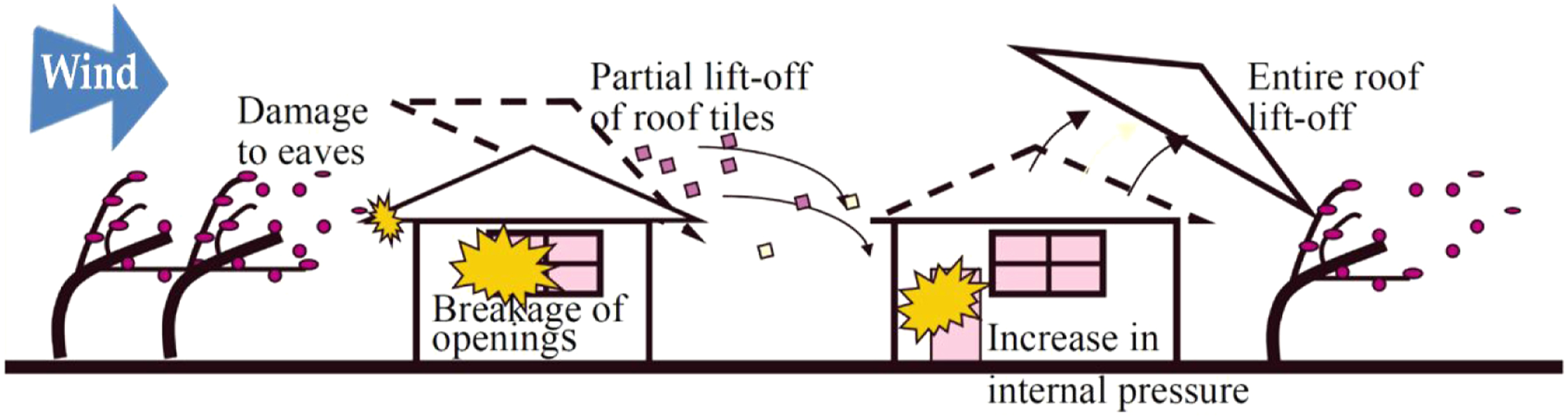
Damage to buildings and structures due to SLSs including tornadoes and thunderstorms
Compared with straight wind, the higher wind speed and the sudden change of wind direction of SLSs can cause severe damage to buildings and structures.
Overturing of 2-story wooden house
Figure 17 shows a two-story wooden house that overturned due to the Tsukuba Tornado on 6 May 2012. This tornado has been officially categorized at Fujita-scale 3 (F3), but the research group of Tokyo Polytechnic University estimated it as F4 based on the overturning of this two-story house and other damage (Okada et al., 2013). To estimate the critical equivalent overturning wind speed, the TPU group collected the detailed design documents of this house and the aerodynamic pressure data of a low-rise hipped-roof model of similar width, breadth, and height ratios as the damaged house from the TPU Aerodynamic Database (http://www.wind.arch.t-kougei.ac.jp/system/contents/code/tpu) (Quan et al., 2007; Tamura, 2009). Thus, the critical equivalent overturning wind speed was estimated at 109 m/s–121 m/s (Okada et al., 2013). Two-story wooden house destroyed down through foundation due to Tsukuba Tornado in Japan on 6 May 2012 (Okada et al., 2013).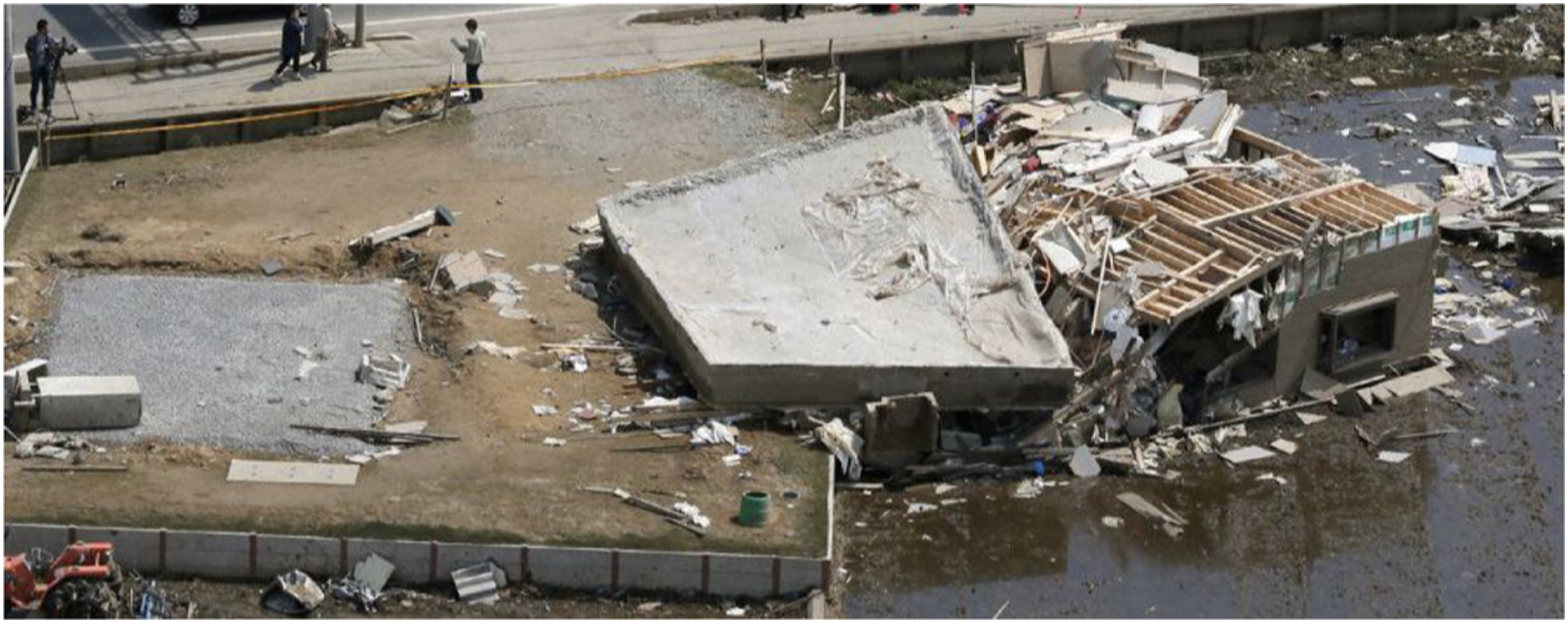
Here, a stationary, straight, horizontal wind is assumed, and the effects of vertical components of the flow, and sudden changes of wind speed, wind direction, atmospheric pressure and so on are not considered, and the estimated wind speed cannot be the same as the real wind speed.
Sudden and unexpected change in internal pressure
Roof damage initiated by openings in windward walls is discussed in the previous section. (Figure 1(b)) and 1.5 (Figure 13(b)), where the internal pressures suddenly shifted to positive values, resulting in large uplift forces acting on roofs. Here, an opposite case is introduced. Figure 18(a) shows outside and inside views of partial damage to roof panels of a steel-frame low-rise supermarket building due to an F2 tornado in Nobeoka, Miyazaki, Japan on 17 September 2006 (Tamura et al., 2018). Damage to roof sheet and inward collapse of entrance sashes and doors of a supermarket building due to F2 tornado in Nobeoka, Miyazaki, Japan on 17 September 2006 (Tamura et al., 2018): (a) Damage to roof panel (courtesy of Home Improvement Hirose) (b) Inward collapse of entrance sashes and doors.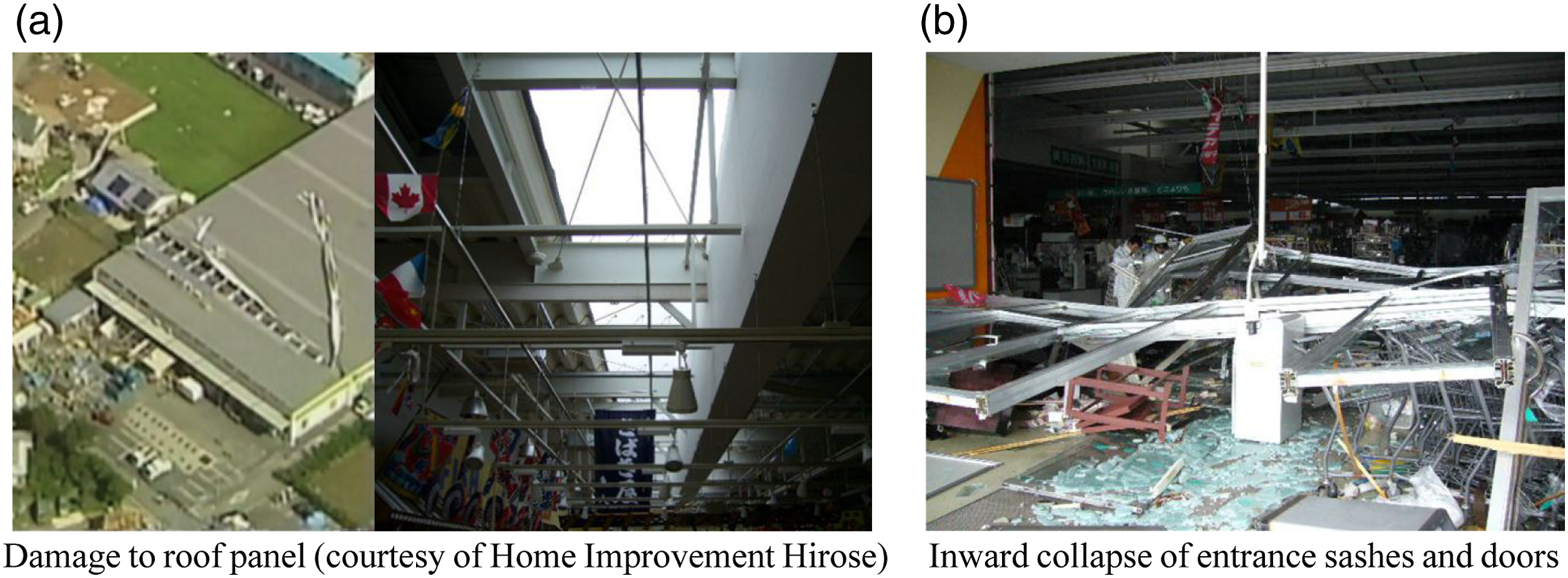
The damage scenario was as follows. Wind-borne debris impacted many points, around 300–400 traces, on the wide roof surface causing a lot of minor damage to the roof panels before the main body of the tornado arrived. Next, a partial but serious breakage of a roof panel was caused by the main body of the tornado, as shown in Figure 18(a). Then, the internal pressure was immediately reduced and became more negative because of the negative external pressures acting on the opening part of the roof panel. This sudden decrease in the internal pressure enhanced the inward force acting on the entrances in the windward wall, and the sashes and doors were pulled in, as shown in Figure 18(b). Unfortunately, one person standing near the entrance was crushed and killed. We should be aware of such sudden or unexpected changes in internal pressures, which can trigger serious damage to buildings.
Possibility of catastrophic incidents
A limited express ‘Inaho-14’ of the Uetsu Line was derailed and overturned at 19:14 on 25 December 2005, in Shonaicho, Yamagata, Japan due to an SLS, which was estimated as an F1 tornado (Tamura et al., 2007) (Figure 19(a)). The train was traveling at around 100 km/h and crashed into a RC building. As a result, 5 people were killed and 33 were injured. Another derailment and overturning of a limited express ‘Inaho-9’ of the Nippo-Line occurred at 13:50 on September 17 the next year, 2006, due to an F3 tornado in Nobeoka, Miyazaki, Japan (Figure 19(b)). This was in the daytime, and the train driver was able to see wind-borne debris flying across the sky ahead of the train, As a result, he was able to stop the train and nobody was killed. In Japan, almost 30% of tornadoes cross railway lines (JST Report, 2008), and such accidents occasionally happen. Derailments and overturning of limited expresses due to tornadoes in Japan: (a) Derailment of Inaho-14 in Shonaicho, 2005 (b) Derailment of Nichirin-9 in Nobeoka, 2006 due to F1 tornado (courtesy of Shonai-Nippo).
A river cruise ship ‘Dongfang zhi Xing (Oriental Star)’ went down due to a downburst (SCPRC, 2015) at 21:32 on June 1, 2015, on the Yangtze River in Jianli, Hubei, China, and 442 passengers and crew died. The number of aircraft accidents due to downbursts have reduced recently, due to the great contributions of Ted Fujita (1920–1998) from the University of Chicago and worldwide deployments of Doppler radars, but aircraft accidents due to SLSs are still happening.
Accidents due to SLSs of mass transportation systems including train derailments and overturnings, ship sinkings, and aircraft crashes are urgent issues to be resolved. To ensure safe train operation, a tornado detecting and warning system using Doppler radars has been implemented in Japan (Fujiwara et al., 2019; Suzuki et al., 2019).
Design principles for buildings/structures with different social importance and influence
Difference between TCs and SLSs in building design
Differences between TCs and SLSs in building design are discussed in this section. SLSs include tornadoes, down bursts, gust fronts, and so on.
Design criteria by codes/standards/regulations for general buildings
As in many other countries, the Building Standard Law of Japan (BSLJ) requires wind-resistant design of general buildings against two different load levels: the 50-year-recurrence wind load and the 500-year-recurrence wind load. For the 50-year-recurrence wind load, an allowable stress design of main frames is specified and no falling off of cladding and components is required. For the 500-year-recurrence wind load, ultimate-state design of main frames is specified. However, because of the mean force component and the relatively long excitation time, fully plastic design is not allowed in the wind-resistant design of buildings, unlike in seismic design. Incidentally, in the BSLJ, cladding and component design is not obligatory for the 500-year-recurrence wind load, which is irrational as discussed in the latter section.
The annual probability of an individual building encountering a tornado in Japan is very low, e.g., 2.6 × 10⁻⁵ and the equivalent recurrence period is around 40,000 years (JST Report, 2008), and that of encountering strong tornadoes equal to F2 or higher is 4.4 × 10⁻⁶ and the equivalent recurrence period is around 230,000 years (JST Report, 2008).
Considering the 50-year- or 500-year-recurrence wind load levels assumed in the BSLJ, tornadoes are quite rare events for individual general building design. Thus, it is commonly understood that designing general buildings against SLSs including tornadoes and thunderstorms is not economically rational, so only life-saving should be considered, and reliable and accurate warning systems are expected to be established. Establishment of accurate and reliable warning systems for SLSs is also very necessary for minimizing accidents of mass transportation systems (Fujiwara et al., 2019; Suzuki et al., 2019).
Crucial difference between TCs and SLSs
Comparisons of wind speed ranges (3s-gust, m/s) specified for F-Scale (Fujita, 1971), EF-Scale (TTU, 2004) and JEF-Scale (JMA, 2015).
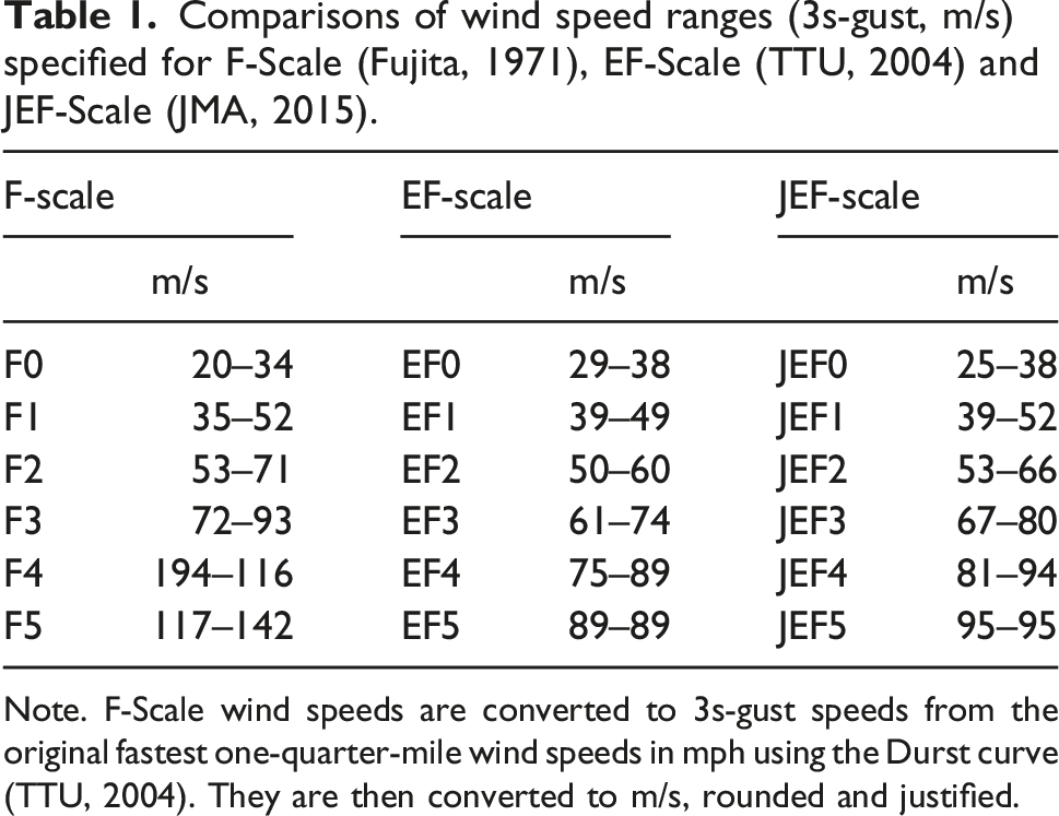
Note. F-Scale wind speeds are converted to 3s-gust speeds from the original fastest one-quarter-mile wind speeds in mph using the Durst curve (TTU, 2004). They are then converted to m/s, rounded and justified.
We have effective warning systems for TCs, and the information can be opened to the public in various ways including TV broadcasts. Once a TC is recognized, we can receive reliable information on its intensity, size, future track, and so on. Thus, we can appropriately prepare for it, such as by cancelling outdoor events and outings, closing storm shutters, protecting or reinforcing windows and doors, and so on.
However, no effective warning systems are available for tornadoes or downbursts. For example, in Japan, we have a tornado warning system, where the JMA predicts the development and movement of supercells and dispatches a ‘tornado warning’ and a ‘tornado occurrence-probability nowcast’ based on meteorological observation data and analyses. However, its accuracy and reliability are not very high, and the lead time is insufficient for some buildings and structures. Therefore, they basically encounter tornadoes or downburst without sufficient preparations.
The performance of buildings and structures under tornadoes or downbursts cannot be the same as for TCs. For residential houses, glass windows are basically protected by storm shutters in the case of TCs, and debris impacts can be resisted to some extent. In the case of tornadoes and downbursts, non-protected glass windows are easily broken by debris impacts or pressures, and they can cause blow-off of entire roofs. According to the estimation of critical wind speed for roof scattering with and without breakage of windows in the windward wall, the critical wind speed can be 30%–40% higher without window breakage, e.g., Okada et al. (2013). Therefore, roughly speaking, if the critical wind speed was the same as the design wind speed, 56 m/s (3s-gust), for TCs, the critical wind speed for tornadoes could be reduced to 40 m/s.
It should be noted that buildings are more vulnerable to tornadoes and downburst than to TCs.
Conditional Buildings and structures
There are many types of buildings and structures designed under the assumption that they will be controlled or maintained in strong wind events, regardless of wind climates.
Movable roofs, freight handling facilities, scaffoldings, cranes, various net/sheet supporting structures, and so on are in this category, and are defined as ‘conditional buildings and structures (CBSs)’ in this paper. For strong winds, special treatments and cures are necessary as follows: movable roofs should be closed; nets and sheets should be removed or tied; crane operation should be suspended; mobile facilities should be stopped and locked; and so on. These structures are more vulnerable to winds than general buildings. For safe operation and usage of CBSs, well designed operation manuals should be prepared and strictly observed to guarantee design assumptions.
As mentioned in the previous section, an efficient warning system is available for TCs and synoptic winds, but not for SLSs. Thus, damage and collapse of scaffoldings, cranes, and net supporting structures have often occurred, as shown in Figure 20. Responsible persons for operation, management and maintenance of CBSs should pay careful attention to daily meteorological conditions, and safer and earlier decisions should be made. If meteorological warning information is combined with signs of weather and sky, they can be efficiently utilized to minimize damage and failure of CBSs, even if the warning system is not very accurate. Damage to conditional buildings and structures due to strong winds: (a) Collapse of cranes (courtesy of K. Cho) (b) Collapse of scaffoldings (Ohdo, 2007) (c) Collapse of net-supporting structures for driving range.
Building lifetime and design load
In this section, the relation between design load level and lifetimes of individual buildings and elements including temporary buildings is discussed. Tamura et al. (2018) investigated the relation between design load level and the lifetime of individual buildings and elements, and concluded that there is no clear theoretical background to a lower design load for a shorter lifetime for buildings and elements. As this topic is very important for realizing wind-induced disaster risk reduction (DRR) due to SLSs and TCs, the design load level of claddings/components and of temporary buildings are reviewed in this section by referring to Tamura et al. (2018).
Design load Levels for main frames and cladding/components
As mentioned in the previous section, the BSLJ requires main frames to be designed based on a 50-year-recurrence wind load and a 500-year-recurrence wind load, while it requires claddings/components to be design based on a 50-year-recurrence wind load only. Thus, there seems to be an implicit consensus that the design load level for claddings/components can be lower than that for main frames.
In main frame design, the same external wind pressure/force coefficients are generally used for both 50-year-recurrence and 500-year-recurrence wind load levels. This suggests that the original building configurations are maintained even for the ultimate state corresponding to the 500-year-recurrence wind load level. This means claddings and components should not be broken or torn off even for the 500-year-recurrence wind load level. It should also be emphasized that wind-induced damage to buildings is generally triggered by small damage to claddings/components, which can develop to a larger scale and more severe damage to main frames. In addition, as mentioned in the previous section, it can also cause significant losses of property inside buildings and social functions of buildings. Thus, BCP cannot be maintained, and building owners and society can suffer deathblows. As is also pointed out, damaged claddings and components become wind-borne debris and create a ‘damage chain’ as mentioned in the previous section. Therefore, we need to minimize damage to claddings and components.
Conversely, some people say that the claddings and components are replaced at certain predetermined intervals. Thus, they advocate that the lifetimes of claddings and components are generally shorter than those of main frames, so their design wind load levels can be lower. It is true that some individual cladding elements and members are periodically replaced because they are more directly exposed to wind, rain, solar heating, and so on, and deteriorate more quickly than main frames. However, it should be noted that they are replaced with identical cladding elements and members, so they always exist and are never permanently removed as long as the building exists. In short, replacement of individual cladding elements and members are maintenance actions to maintain or recover their quality and performance up to the level assumed in the design stage. Therefore, the short replacement intervals of specific cladding elements cannot be a reason for reducing the load level. Theoretically, there is no reason to accept a lower level of wind load for cladding/components than main frames (Tamura et al., 2018).
Therefore, unless there are special reasons, the design load level for claddings/components should be the same as for main frames.
If special treatments are considered to prevent progressive failures triggered by damage to claddings/components or generation of wind-borne debris, they may constitute reasons for adopting different design criteria.
Design load Levels for temporary buildings including construction offices and scaffoldings
Related to the above discussion about replacement intervals and the design load levels of cladding/components, we now discuss wind load levels for so-called “temporary buildings” including scaffoldings and construction offices.
For temporary buildings including construction offices, Article 85 of the BSLJ specifies reduced design loads and less strict construction methods. As in the BSLJ, other codes and standards such as AIJ-RDKTB (2013), ASCE 37-14 (2019), and AS/NZS 1170.2 (2021) also allow reduction of design wind speeds for temporary buildings and structures. Thus, there is a common consensus that design load levels for temporary buildings can be lower than those for general buildings.
Thus, construction offices are basically more vulnerable to wind and seismic excitations. However, Tamura et al. (2018) pointed out the contradictions of this theoretical background.
Similarly, design loads for scaffoldings are much lower than those for general buildings. For example, in Japan, SCEAJ-TRSSW (1999) specifies design wind loads for scaffoldings based on 1-year-recurrence wind speed. The reason for this is that the average setting period T S of scaffoldings at one specific construction site is as follows (SCEAJ-TRSSW, 1999).
The British Standard requires design wind loads based on 2-year-recurrence wind speeds (BS EN 12812, 2008), and Chinese Codes/Standards require design wind loads based on 10-year-recurrence wind speeds (GB 50009, 2012; GB 51210, 2016; JGJ130, 2011; JGJ/T 128, 2019). These are slightly higher than those of SCEAJ-TRSSW (1999), but much lower than those for general buildings, probably for similar reasons as for SCEAJ-TRSSW (1999).
However, as mentioned above, Tamura et al. (2018) pointed out the irrationality of this preconception. The average existence period of a specific scaffold at an individual site is short, but it moves to other locations and continues to exist. Figure 21 shows schematic aerial views of a virtual city, where the green rectangular blocks indicate construction sites and the white blocks indicate general building sites. Thus, the green blocks represent temporary buildings such as construction offices and scaffoldings, and the white blocks represent permanent general buildings. Snap shots of locations of construction sites (green blocks) and general building sites (white blocks) in a city every 6 months (Tamura et al., 2018): (a) T (present) (b) T + 6 months (c) T + 12 months (d) T + 18 months.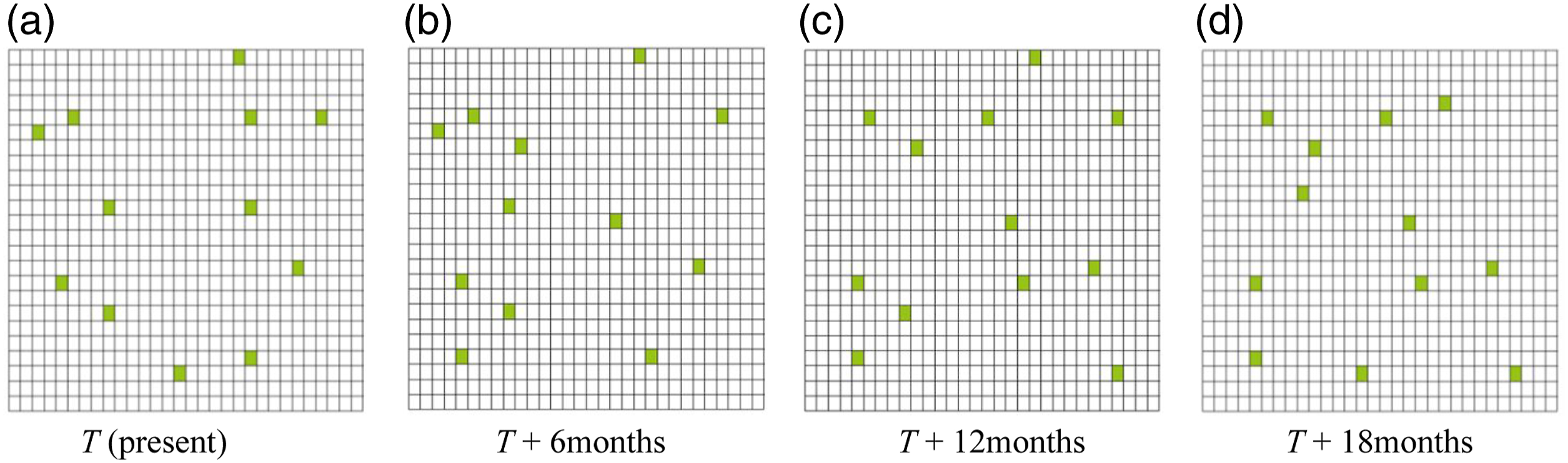
It is clearly seen that the construction sites are moving, but the number of construction sites remains almost constant. It is not clearly recognized, but the general building sites are moving too. If a strong cyclone struck this virtual city, all the buildings would of course experience the same level of wind loads, whether they were general buildings or temporary buildings. The numbers of temporary buildings (green blocks) and general buildings (white blocks) are quite different, but their essential features are the same. Thus, there is no essential difference between permanent general buildings and temporary buildings regarding existence period and external actions.
More importantly, construction offices are used in the same way as general buildings, where they have meetings, make drawings, conduct analyses, perform administrative works, eat meals, even sleep and so on. Once you get a job in a construction company as a construction engineer, you stay and work in these types of ‘temporary’ buildings until you retire, say for 40 years (Tamura et al., 2018). For you, there is no rational reason to make them of lower quality than the headquarter office of your company.
Tamura et al. (2018) also proved that there is no relation between design load level and length of individual use or life-time, raising examples of average rental period of rental cars and periodic replacements of parts of airplanes. Incidentally, many people raise the removal of nets and sheets of scaffoldings in strong winds as a reason for reduction of design load level. This can of course be a reason for reduction of aerodynamic force coefficient C
f
and the projected area A
f
in the following wind load estimation formula,
Of course, if a temporary building exists only for a winter season, for example, we need not consider typhoons, which strike the eastern Asian region only in warm seasons. Therefore, the effects of such a local wind climate can be taken into account in the design wind speed estimation. In addition, if temporary buildings and facilities are utilized for only a very short period, e.g. a few days, and its wind climate is predictable, TCs may be omitted from the design wind speed estimation. However, those buildings and facilities should be treated as CBSs, and be strictly operated in accordance with the predetermined manual.
Furthermore, it should be noted that the required performance of temporary buildings is not necessarily the same as that of general buildings.
Anyway, when we discuss the design load level of so called ‘temporary buildings’, we should reconsider the real meaning of the individual life-time of each building. Then, the design principle focusing on a group or an assemblage of unspecified buildings rather than an individual specific building might be necessary, i.e. city total and/or nation total merits, especially for codes and standards.
Essential parameters for determining design load level
As the design load level cannot be decided based on the life-time or length of individual use of a building or its parts, Tamura et al. (2018) pointed out the necessity to re-examine the minimum life cycle cost (LCC) concept based on the lifetime of an individual building. They also pointed out that BCP is an important issue not only for the private sector but also for a city or a nation, and securing BCP can be a key to the security of a city or nation. Anyway, the design load level should be determined based on the following parameters. (1) Importance (2) Social, economic and physical impacts of damage to buildings/structures on society
An acceptable probability of failure should be examined, and it cannot be irrelevant to the economic power of the nation. Of course, cultural and historical backgrounds should be also considered, and some calibrations might be required for traditional methods and conventional policies that have already gained social consensus, so the problem is not simple. Anyway, especially when formulating codes/standards, load levels should be decided focusing on a group/assemblage of buildings rather than an individual specific building. Even for the minimum LCC concept, the city total or nation total LCC should be considered, and definitions of “life cycle”, “life-time” or “length of use” might be key issues to be carefully examined.
Design principle for highly important and influential buildings and structures
Owing to the importance and social impacts, sufficient attention should be paid to the design load levels of these highly important and influential buildings and structures under strong winds, especially SLSs. Also, the ways to deal with future wind-related disasters are discussed in this section.
Increasing demand and importance of electricity
Figure 22 shows power transmission towers that collapsed due to Typhoon Faxai in 9 September 2019, in Chiba Prefecture, next to the Tokyo Metropolitan area. Many utility poles also collapsed due to this typhoon and a prolonged and widespread power outages occurred, which took 19 days for complete recovery. Modern society is powered by electricity, and almost nothing can be done without it. As even water cannot be utilized without electricity, people were in a serious situation for a long time. Collapse of power transmission towers due to Typhoon Faxai on September 9, 2019, in Chiba, Japan (METI, 2019): (a) Base part of a collapsed tower (b) Top part of a collapsed tower (Courtesy of Kanto Industrial Safety & Inspection Department, Ministry of Economy, Trade and Industry).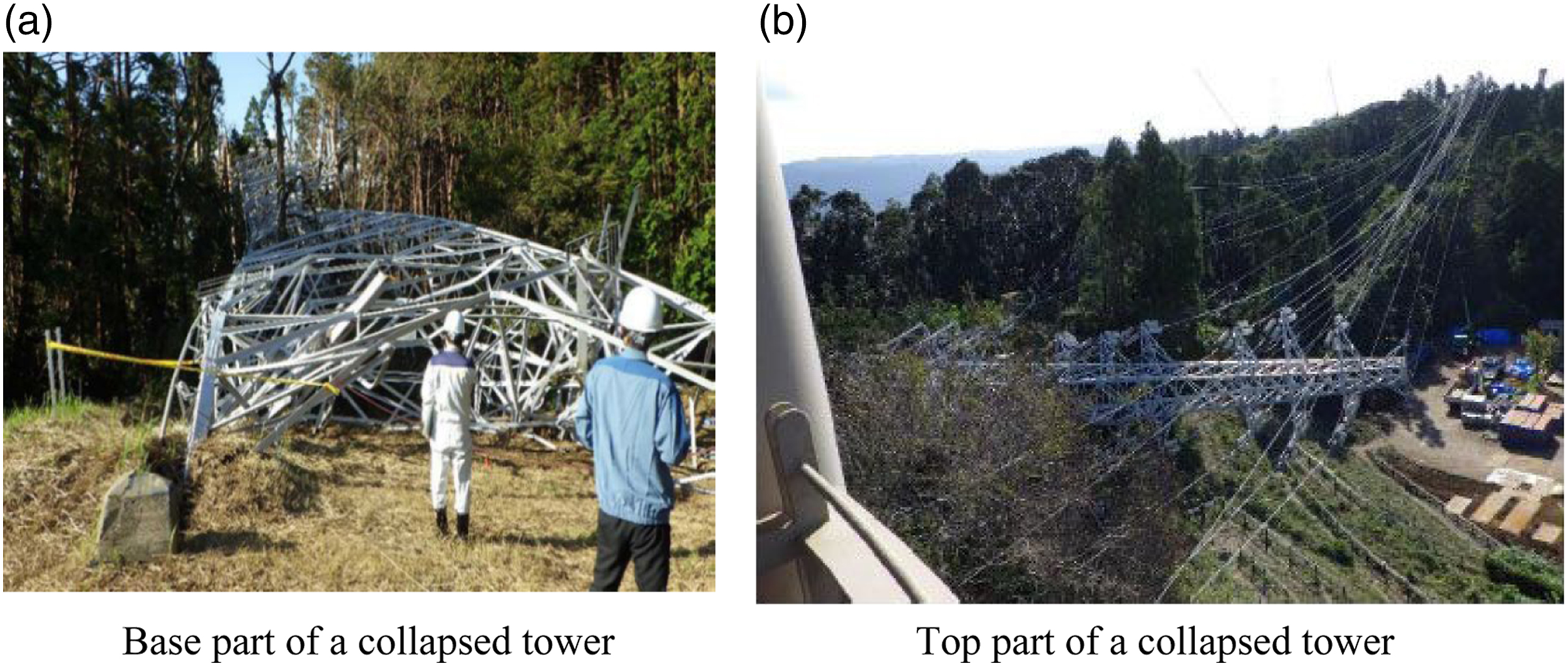
The collapsed transmission towers were designed following the Electrical Equipment Technical Standards (1965) based on JEC-127 (1965). The design load level specified in JEC-127 (1965) is essentially similar to the current version, and has not changed since at least 1932. These power transmission structures have been designed with a lower load level than for general buildings, because they are generally located in non-populated areas and nobody lives inside them. Therefore, collapse of those structures might not cause serious losses to society. However, as mentioned above, the current situation is quite different from the past, and societal electric power demand has recently significantly surged. The collapse of power transmission facilities has significant impacts on our society, similar to failures of thermal and hydraulic power plants. Reconsideration and revision of the design load levels of those structures and facilities are urgent issues.
Wind turbines and solar panels are usually located in unpopulated areas, so the impact of failures can be less significant if they cover only limited areas. However, for these electric facilities and infrastructures, including thermal power plants, hydraulic power plants, power transmission lines, substations, wind farms, solar farms and so on, different design load levels can be applied depending upon their importance and degree of influence on society.
Similar to railways mentioned in the previous section, power transmission cables and towers compose line-like structures extending over land, and have a much higher possibility of encountering tornadoes than individual buildings. Thus, tornado effects should be considered in the disaster management these facilities.
Tornadoes for urban disaster planning
As mentioned in the previous section, in many countries, general buildings are not designed against tornadoes, because the annual probability for an individual building encountering tornadoes is much lower than for TCs and other synoptic winds. However, a city has a much higher annual probability, e.g., 90-year- ∼700-year-recurrence level (JST Report, 2008), of encountering tornadoes than an individual building, so tornadoes should be considered in urban disaster planning.
Highly influential and important facilities including nuclear power plants
One highly influential and important facility is the nuclear power plant (NPP). Temporary shutdowns of NPPs were made in the US due to tornadoes at Dominion Virginia Power, Surry, VA and Browns Ferry Nuclear Plant, Athens, AL, on April 16 and 27 in 2011, respectively (Prevatt et al., 2015). Incidentally, these shutdowns happened almost 1 month after the Fukushima Daiichi NPP accident due to the Great East Japan Earthquake induced tsunami. The reason for the shutdowns of NPPs in the US were collapses of external power lines due to tornadoes. Back-up generators immediately kicked in at those two NPPs, so no serious accidents happened. The scenario up to activation of back-up generators was the same for the Fukushima Daiichi NPP. However, in the Fukushima case, the back-up generators were also destroyed around 50min later by the big tsunami, which had a 14m or more run-up height.
As is well-known, multiple tornadoes can happen, and there is a possibility of damage to back-up generators due to consequent tornadoes. Thus, fail-safe counterplans should also be prepared for back-up generators.
The following facilities and structures, including NPPs (Reactors), huge liquefied natural gas (LNG) storage tanks, spent nuclear fuel installation facilities, nuclear fuel storage facilities, uranium enrichment facilities, toxic waste processing plants, toxic substance storage facilities, industrial waste disposal equipment and so on, are highly influential for society, and special consideration should be taken in their design including for the effects of tornadoes (JST Report, 2008).
As discussed in the previous section, the importance and societal impact of failure of a target building or structure are key issues. However, it is very difficult to decide an acceptable probability of failure and design load level for such highly influential buildings and structures.
There are several design guides and regulations for tornado effects on NPPs, e.g. ANSI/ANS-2.3 (1983) and RG 1.76 (2007) in the US and JNES-TPU (2011) and NRA Guide (2013) in Japan. The US might be regarded as the pioneer country for establishing these design guidelines. They adopt an annual exceedance probability of 10−7 to determine the design tornado following Markee et al. (1974). JNES-TPU (2011) also proposed a design tornado model also based on an annual exceedance probability 10−7. However, NRA Guide (2013) basically follows the proposal of JNES-TPU (2011), but the design load level for tornado effects is reduced to the 10−5 probability level, to balance with other external loads including seismic excitation. However, the impacts of failure of NPPs cannot be limited to the nation in which it is constructed, because the effects of failure could immediately propagate to many other countries. Therefore, they should be treated as a worldwide issue, and a worldwide consensus should be obtained. Cooperative studies on the design load levels of NPPs are necessary.
In addition to electric facilities discussed in the previous section, the buildings and structures, including super-tall buildings, local government offices, fire stations, hospitals, evacuation facilities, disaster prevention centers, data/computer centers and so on, are highly important for society, and special consideration should also be given to them.
How to cope with future wind-related disasters
Figure 23 shows global average temperature anomalies relative to the 1850–1900 average, which is an estimate of the pre-industrial climate, for the 170 years from 1850 to 2019 (Berkeley Earth, 2020). It remained almost constant for several decades after the Industrial Revolution from the 1760s to the 1830s, but the global average temperature apparently began increasing after around 1900. Global average temperature anomalies relative to 1850–1900 average (Berkeley Earth, 2020).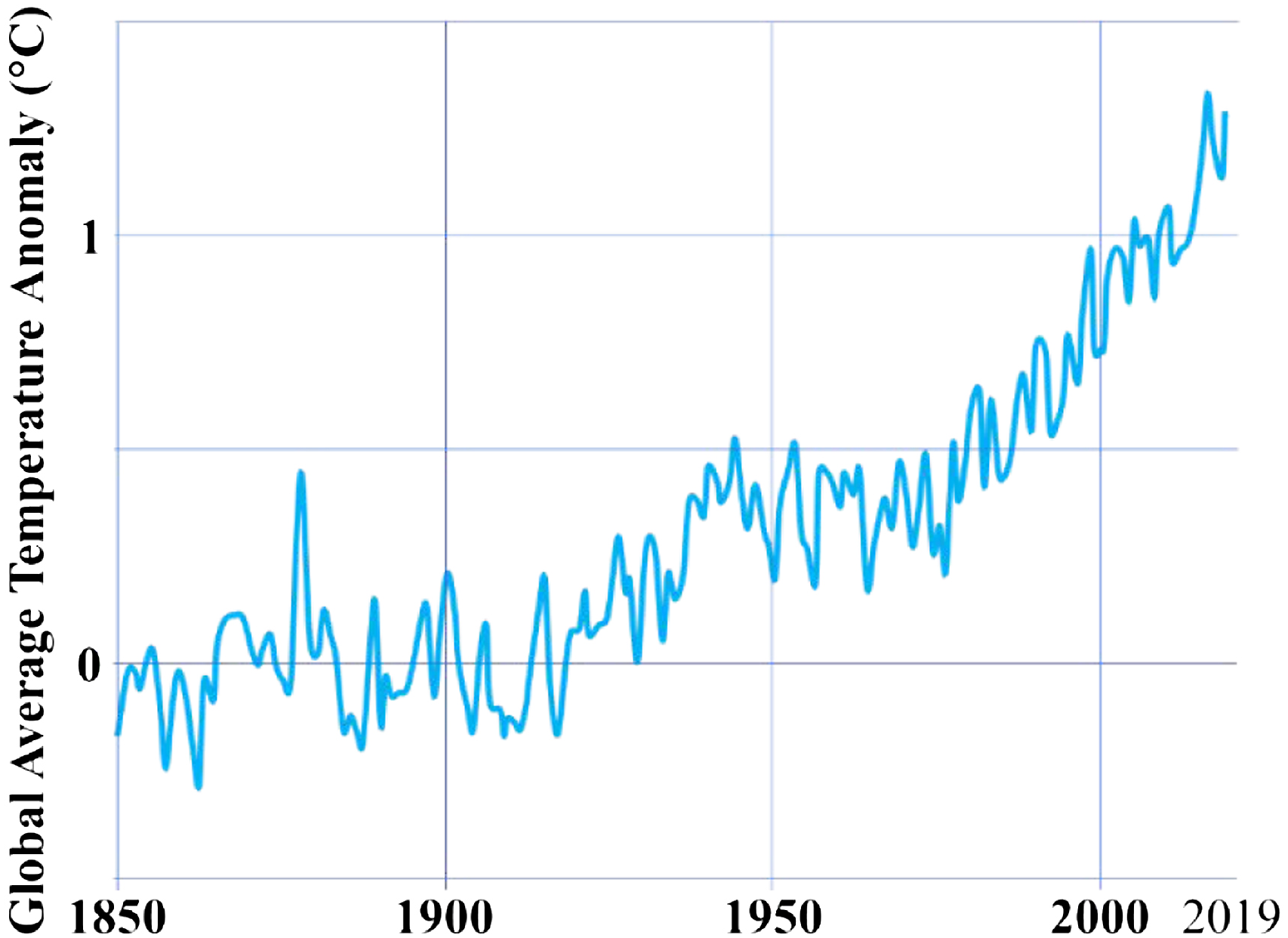
Figure 24 compares the number of worldwide disasters due to natural hazards to various physical causes for the 35 years from 1980 to 2014 (Munich Re, 2014) and the global average temperature anomalies for the same period extracted from Figure 23. The number of disasters and the global average temperatures show clear and strong correlation. More importantly, water-induced floods and mass movements indicated by blue bars and wind storms indicated by green bars have significantly increased recently. As discussed in the previous section, both wind hazards and water hazards occur simultaneously during TCs, and Tamura and Cao (2011) named these two simultaneously occurring disasters ‘wind-related disasters’. It is suggested that the recent increasing trend of ‘wind-related disasters’ is likely caused or at least affected by the global temperature increase. Yearly variations of number of disasters due to natural hazards from 1980 to 2014 (Munich Re, 2014) and global average temperature anomalies for the same period (Berkeley Earth, 2020).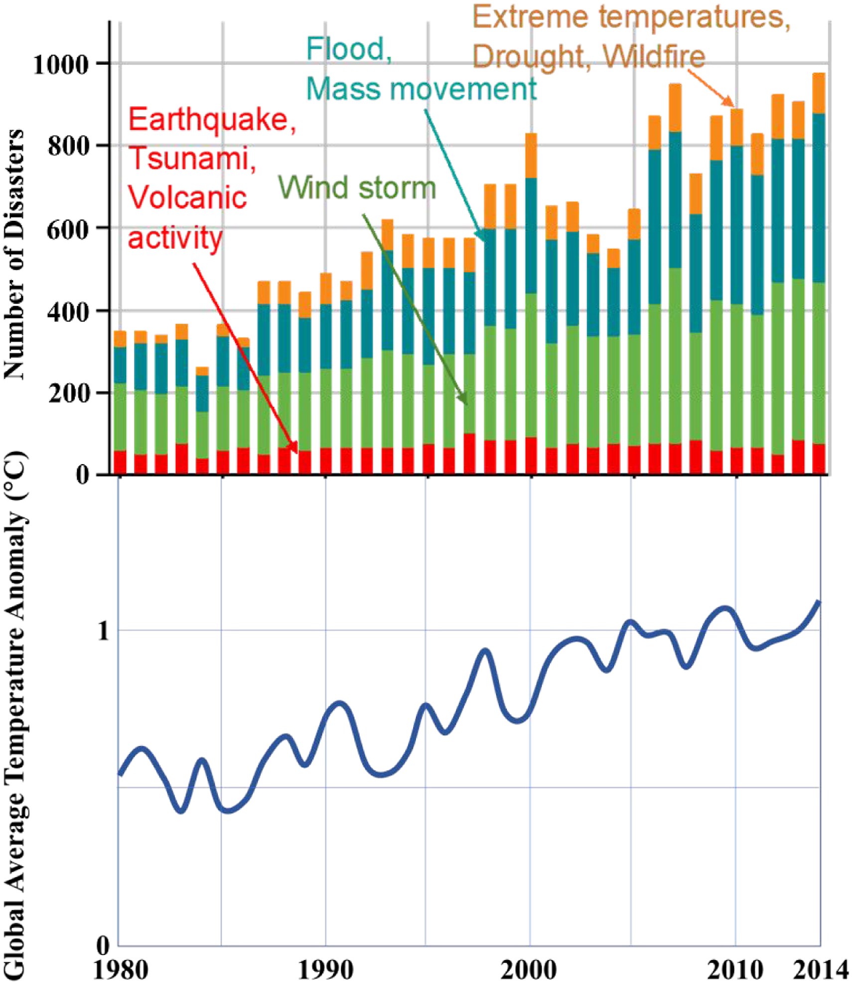
If the increase in global average temperature cannot be stopped, the frequency wind-related disasters will continue to increase, and the current increasing trend will accelerate in the future. Therefore, ‘decarbonization’ is also an essential and urgent issue for DRR.
As discussed in the previous section, the hot spots of economic losses due to natural hazards are in developed countries, while those of fatalities are in developing countries (Tamura et al., 2017). Thus, there is a pressing need for DRR activities for both developing countries and developed countries. In addition, Tamura et al. (2017) emphasized that accurate performance evaluation of buildings and structures, especially of cladding/components, against devastating rare events should be made to avoid repetition of devastating wind-related disasters. Thus, a full-scale storm simulator (FSSS) that can generate extremely strong wind, rain, snow, hail and so on under controlled conditions, is necessary to determine the fracture processes of partial or entire building and structural systems.
Concluding remarks
This paper discussed wind-induced damage to buildings/structures and design principles, with special focus on the difference between SLSs and TCs, temporal and CBSs, and highly important and influential buildings. The following facts are concluded and should be noted. 1. Wind-induced damage/accidents are caused by not only strong winds but also moderate or weak daily winds. 2. Devastating disasters happen due to TCs as the combined effects of wind and water hazards. Water speed effects should be taken into account when estimating water-induced damage to buildings and assessing evacuation timing. 3. The majority of wind-induced damage to large structures show some degree of human errors, suggesting the necessity for more efforts in education and dissemination of aerodynamic and structural knowledge to structural designers. 4. The importance of cladding/component performance should be recognized, and realistically, “Wind Resistant Design of Buildings” is equal to “Cladding/component Design”. 5. The design load level of claddings/components should essentially be the same as that of main frames, unless some special prevention measures for failure progress triggered by claddings/components damage are considered. 6. Because of lack of an efficient warning system for SLSs, buildings are more vulnerable to them than to TCs. 7. CBSs should be carefully operated following operation manuals and signs of weather and sky, especially for SLSs. 8. The design load level of buildings and structures should not simply be decided based on the life-time or the period of individual use. Especially, the design load level of some so-called ‘temporary’ buildings, such as scaffoldings and construction work offices, should be reconsidered. There is no essential difference between general ‘permanent’ buildings and ‘temporary’ buildings regarding both existence period and external action. 9. The design load level should essentially be decided based on the importance and impacts of failures of buildings and structures to society. Some consideration of historical and cultural backgrounds are of course also necessary. 10. The design load level for electric facilities should be re-considered because of the recent surge of importance and demand for electricity. 11. SLSs, especially tornadoes, are excluded from the design targets of general buildings in many countries, because of their low occurrence probability, but highly important or highly influential buildings such as NPPs should consider SLSs as the design target. 12. For tornado effects on NPPs, not only the effects on reactor buildings but also fail-safe counter plans for back-up power generators should be considered. 13. It is difficult to estimate design tornado models, especially their annual probability. The US has promoted pioneer studies and adopted 10−7 as the annual exceedance probability for the design tornado model. 14. To cope with the future hypothesized increase of wind-related disasters, decarbonization and FSSSs are urgently required.
Footnotes
Declaration of conflicting interests
The author(s) declared no potential conflicts of interest with respect to the research, authorship, and/or publication of this article.
Funding
The author(s) disclosed receipt of the following financial support for the research, authorship, and/or publication of this article: This study has been financially supported by the 111 project of the Ministry of Education and the Bureau of Foreign Experts of China (No. B18062), National Natural Science Foundation of China (51720105005), Chongqing Science and Technology Bureau (cstc2019yszx-jcyjX0005) and (cstc2020yszx-jcyjX0007), and the authors are grateful for their support.
