



Abstract
To solve the instability of the compression bars in the space truss composed of GFRP tubes, a composite column with high-strength concrete (HSC) confined by glass fiber-reinforced plastic (GFRP) tube was proposed. High-strength self-compacting micro-expansive concrete with a slump greater than 255 mm was produced under normal-temperature curing conditions and confined by GFRP tubes. A mechanical performance test of the GFRP-confined HSC short column under axial compression was performed. The effects of GFRP tube types, concrete expansion agent, constraint effect, ultimate load capacity, and failure mode of the composite structure were discussed and analyzed through the test. A model of the stress-strain response of the GFRP confined HSC column was proposed. The results show that the 45° fiber-wound GFRP tube has a significant restraining effect on the HSC. The stress-strain relationship increases quadratically in a linear fashion. When the composite column was damaged, the GFRP fiber was broken and the concrete was crushed. The ultimate strength was about 1.5 times that of unconstrained HSC columns, and the loading method has less influence on the results. The expansion agent has a significant effect on the deformation performance of the composite column, and its ultimate strain was about 1.4 times that of the composite column without expansion agent.
Introduction
Fiber-reinforced plastic (FRP) truss structure has been used in structural engineering because of its high strength, low density, and good corrosion resistance (Bai and Zhang, 2012; Chen et al., 2022; Teixeira et al., 2014). Although FRP profiles have excellent tensile properties along the fiber direction (Chin et al., 2015; Feng et al., 2022; Rodsin et al., 2020), their compressive properties were poor (Higgoda et al., 2023), so they could not be directly used in the compression bars of truss structures. An FRP-confined concrete column was a new composite structure that used the FRP tube as a constraining material. Under axial compression load, the FRP tubes constrain the lateral expansion deformation of the internal concrete, resulting in three-dimensional compression, improving the strength and ductility of the confined concrete (David et al., 2019; Gudonis et al., 2013). By applying it to the compression bars of truss structure, the excellent unidirectional mechanical property of FRP profile could be better utilized, effectively solve the traditional steel corrosion problem, improve the stability and service life of the structure, and reduce the overall life cycle cost of the structure (Alsubari et al., 2021; Liu et al., 2014; Rajak et al., 2022).
The research on the mechanical behavior of FRP-confined concrete under axial compression has dealt with normal-strength concrete (Song and Fan, 2016; Hadi et al., 2018; Zavvar et al., 2021). It was shown that the combination of FRP and concrete not only improved the ductility of concrete in the core area, improved the compression, bending and shear performance of composite columns, but also improved the utilization efficiency of FRP materials. In studying the design methods of FRP tube confined concrete, Shahawy et al. (2000) found that the traditional design method of concrete-filled steel tube columns was not suitable for FRP confined concrete. Fam and Rizkalla (2001) observed that the interface condition between the FRP tube and the normal concrete core had no significant effect on its mechanical performance. Pessiki et al. (2001) showed that the restraint efficiency of a square cross-section FRP pipe was weaker than that of a circular cross-section FRP pipe. Lim and Ozbakkaloglu (2014) observed that when the restrained specimen entered the plastic deformation stage, the rate of strain increase decreased as the strength of the unconstrained concrete increased. In the constitutive model study, Samaan et al. (1998) proposed a bilinear model based on the correlation between the expansion rate of concrete and the hoop stiffness of the confining member. The design-oriented stress-strain model for FRP-confined concrete proposed by Lam and Teng was simple, practical, accurate, and widely used (Lam and Teng, 2003, 2004; Teng and Lam, 2004; Teng et al., 2007, 2009). More than two decades of studies have been devoted to establishing the material properties of FRP confined concrete, including such fundamental aspects as its destruction and constitutive model. However, due to the diversity of research objects, the application of existing models has limitations, the research on HSC-filled FRP tube was much less mature than normal strength concrete.
Parallel studies on the microstructure of concrete materials have led to the development of HSC, in which the material microstructure has been optimized to achieve a significant improvement in material properties, such as compressive and tensile strength, ductility, deformation capacity, and durability (Ruan et al., 2018; Wang et al., 2018; Liao et al., 2021). For example, ultra-high performance concrete (UHPC) generally does not use coarse aggregates and uses a certain amount of ultra-fine silica powder to fill the intergranular space and achieve a more compact state (Wei et al., 2019). The high-strength and self-compacting properties of HSC could lead to significantly smaller cross-section for structural members, reduce concrete shrinkage cracks, and the construction was convenient compared to conventional concrete (Gökçe et al., 2018). To further improve the ductility of HSC, researchers have studied FRP confined concrete, which consists of FRP jackets wrapped around the outside of the concrete column (Hodhod et al., 2005; Vincent and Ozbakkaloglu, 2013; Zohrevand and Mirmiran, 2013; Yu et al., 2014; Nguyen and Choi, 2019; Ju et al., 2020). The test results show that FRP jackets would increase the ductility, ultimate strength, and elongation of HSC columns by up to 300%, 198%, and 195%, respectively. However, due to the limitation of curing conditions of HSC or UHPC, it is difficult to produce the concrete confined by FRP tube, so the test model in the existing research was mainly to wind the FRP jackets on the cured concrete column (Dadvar et al., 2021; Liao et al., 2021, 2022; Pour et al., 2021).
In summary, although the concrete confined by FRP tube has been studied, it is not as mature as the concrete confined by steel tube, especially the behavior of the HSC or UHPC confined by GFRP tube is less studied. In this study, a self-compacting micro-expansive HSC short column confined by GFRP tube was designed. In preparing the composite structure, the GFRP tube could be used as formwork, and the self-compacting concrete, which filled into the GFRP tube, could be cured at conventional temperatures without mechanical vibration. Thus, the preparation process of composite structure is simplified. The axial compression performance of the self-compacting micro-expansive HSC short columns confined by GFRP tubes was investigated from three aspects: the types of GFRP tubes, the performance of the HSC, and Interfacial bonding properties of the composite structure. Additionally, modified the monotonic axial stress-strain responses model of Teng based on the experimental result (Teng et al., 2009). The research results provide theoretical guidance for the application of self-compacting micro-expansive HSC short columns confined by GFRP tubes.
The remainder of this paper is organized as follows. First, introduces the preparation, loading and testing schemes of specimens, the basic mechanical properties of GFRP tubes and HSC are tested. Second, the data of the test results are analyzed to determine the influence of different parameters on the mechanical properties of self-compacting micro-expansive HSC short columns confined by GFRP tubes, and the constraining effect of the composite structure is analyzed. Finally, an analysis model is proposed to guide the design of self-compacting micro-expansive HSC short columns confined by GFRP tubes.
Experimental programs
Specimen preparation
Prefabricated GFRP tubes were used in the experimental. It was a random selection of a manufacturer in the Chinese market to reflect the mechanical properties of the GFRP tube used in engineering, the fiber distribution in GFRP tube was shown in Figure 1. The three research areas of interest were the types of GFRP tubes, the presence or absence of expansion material in the RPC, and the stress-strain mode of the composite structure. This paper focuses on the effects of GFRP tube type, expansion agent and loading method on the structural performance of HSC confined by GFRP tubes. The type of GFRP tube.
Experiments were designed with eleven groups of HSC columns confined by GFRP tube, three groups of GFRP columns without concrete, and two groups of HSC columns unconfined by GFRP tubes. All 48 specimens were 100 mm diameter (D), 300 mm height (H), and 5 mm wall thickness (t) GFRP tubes. Three specimens were tested in each group to minimize testing error, and the data were averaged. Three specimens were tested in each group, the data with a large variation in the specimens were removed, and the remaining two data were averaged to minimize testing error.
Test setup and instrumentation
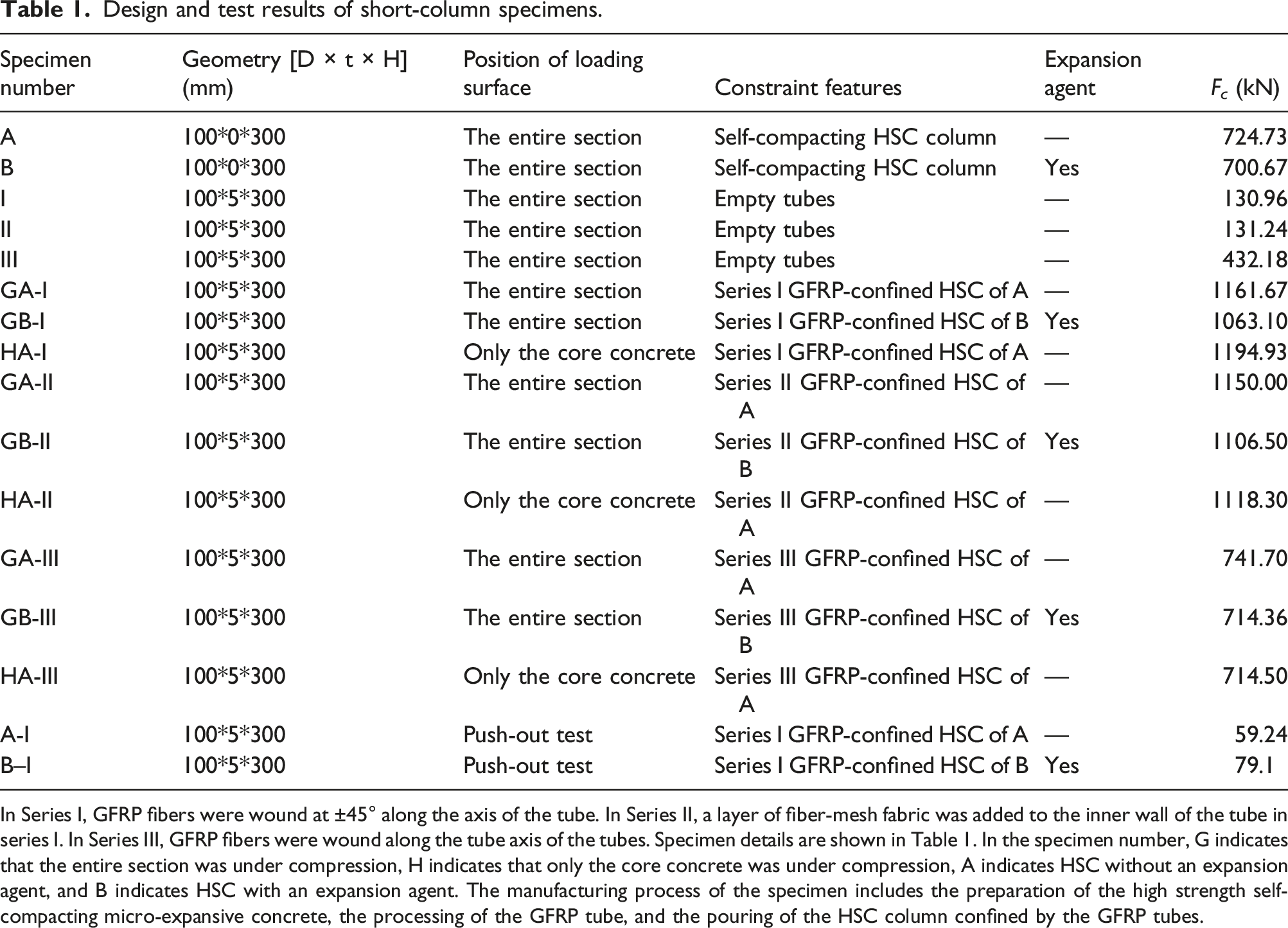
The GFRP tube filled with HSC was wet cured at room temperature for 28 d. After curing, two layers of 30 mm thick CFRP fabric were wrapped around both ends of the specimen to reinforce the end and prevent damage to the specimen during loading. Before loading the specimen, both ends of the specimen were levelled with quartz sand so that the end face of the specimen was perpendicular to the axis. Figure 2(a) shows the load arrangement. An axial compression test was performed on a 2000 kN pressure testing machine. A monotonic step loading system controlled by a load machine was used. The loading rate was 0.8 kN/s before 70% of the estimated ultimate load was reached and 1.2 kN/s of this value afterward, and the loading value of each step was 1/10 of the estimated ultimate load. When the estimated peak ultimate load was almost reached, slow continuous loading was applied until the specimen was damaged. In this test, the strain data of the specimen were obtained from strain gauges (SG) evenly distributed around the specimen. A total of 6 SGs with a length of 50 mm were used on the surface of the FRP pipe, Figure 2(b) shows the SG configuration. Loading device and measuring point arrangement. Design and test results of short-column specimens. In Series I, GFRP fibers were wound at ±45° along the axis of the tube. In Series II, a layer of fiber-mesh fabric was added to the inner wall of the tube in series I. In Series III, GFRP fibers were wound along the tube axis of the tubes. Specimen details are shown in Table 1. In the specimen number, G indicates that the entire section was under compression, H indicates that only the core concrete was under compression, A indicates HSC without an expansion agent, and B indicates HSC with an expansion agent. The manufacturing process of the specimen includes the preparation of the high strength self-compacting micro-expansive concrete, the processing of the GFRP tube, and the pouring of the HSC column confined by the GFRP tubes.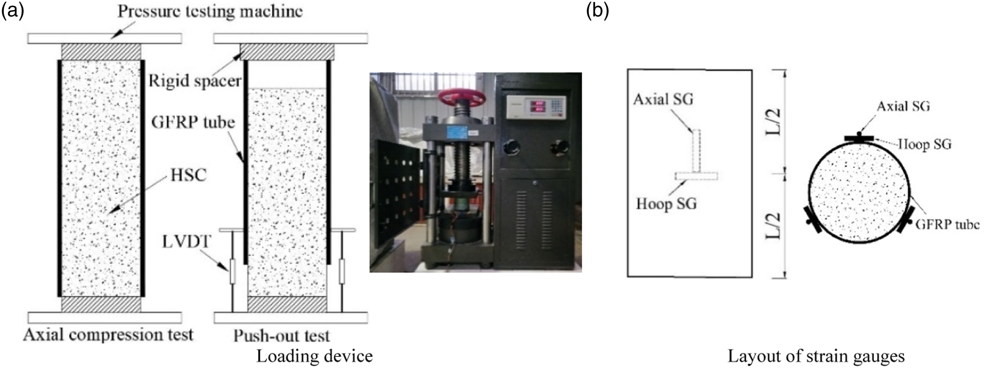
Material properties
Concrete
(1) Test materials. Cement was P.O 42.5 ordinary Portland cement according to Chinese standard. Silica fume contains 90% of SiO2 and has a fineness modulus of 5000. The fineness modulus of quartz sand was 40 to 70, and the crystal grain size was 0.261 to 0.4 mm. The fineness module of quartz powder was 300 and the crystal grain size was 0.044 mm. The water reducer was the QS-8020 polycarboxylic acid superplasticizer, with a settled density of 650 to 850 g/L, the active components was greater than or equal to 90%, the PH value was 7.0∼9.0 in 10% aqueous solution, and the water reduction rate of the mortar was greater than or equal to 23%. Expansion agent was the UEA expansion agent within sulfur aluminate-based, the 15-day longitudinal restrained expansion rate of concrete was more than 0.02%, and the 180-day longitudinal restrained dry shrinkage rate was less than 0.02%.
It should be noted that in order to make the slump of HSC greater than 255 mm, instead of using coarse aggregate, a certain amount of ultrafine silica powder is used to fill the intergranular space to achieve a more compact state and improve the purpose of structural strength, and the material collapse is controlled by water reducing agents.
mixing ratio and material properties of self-compacting RPC.


Mechanical properties of HSC columns.
According to Figure 3(a) and (b), the degree of concrete spalling on the surface of A column was lower than that of B column. From Figure 3(c), the stress-strain curve of the unconstrained HSC columns shows three stages. First, the elastic deformation stage, the stress-strain curve increased linearly, and there was no change on the specimen surface. Second, the nonlinear deformation stage, the stress-strain curve increased nonlinearly; when the ultimate stress reached about 80% in the plastic deformation stage, vertical cracks appeared at the end of the specimen, and the HSC on the column fell off to varying degrees. Third, in the failure stage, many axial cracks appeared on the column; with a loud noise, the HSC on the column fell off in large numbers, and the specimen failed. The ultimate stress of the specimens was 92.32 MPa in group A and 89.26 MPa in group B, but the ultimate strain of the specimens in group B was greater than that in group A. It was found that the stress-strain of A and B increased at different rates during the plastic deformation stage, and the damage of B column was more serious, due to the expansion agent had influence on the compactness of the structure.
GFRP tubes
Mechanical properties of the GFRP tubes.

Where f c, ′ gfrp is the axial compressive strength, ε c,gfrp is the peak strain value, E s is the initial modulus of elasticity, E s ′ is the modulus of elasticity of axial tangent, ν is the poisson’s ratio, f h, ′ gfrp is the ring tensile strength, ε h,gfrp is the peak tensile strain value at the limit, E t is the Initial modulus of elasticity in the ring test, E t ′ is the tangent modulus of elasticity in the ring test.
For comparison with the composite column, three series of GFRP tubes with a thickness of 5 mm, an inner diameter of 100 mm, and a height of 300 mm were fabricated for the axial compression test. The loading system and strain gauge arrangement were the same as for the HSC columns confined by the GFRP tubes. The failure modes and stress-strain data of the specimens were shown in Figure 4. Mechanical properties of the GFRP tubes.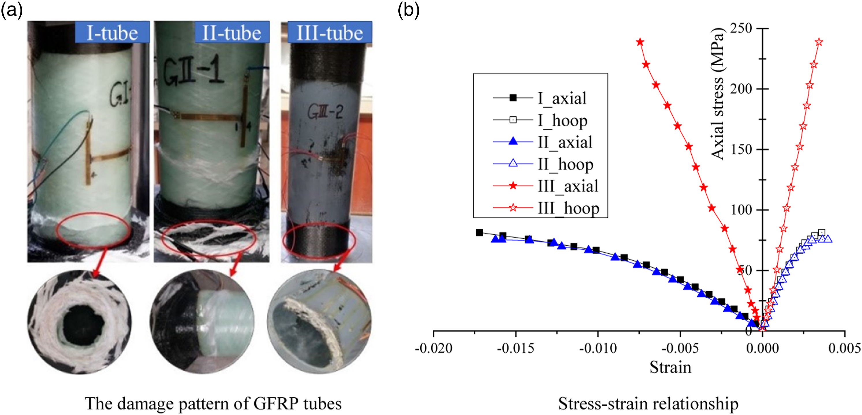
During the loading process of the specimen, the GFRP tube showed no changes in the early loading stage. When the load was approximately 85% of the ultimate load, the GFRP tube began to crack at the end of the load. As the load increased, the cracks at the end propagated in the fiber winding direction. The cementation material around the cracks was detached in some areas, the circumferential fibers broke, and buckling failure occurred at the end of the member, as shown in Figure 4(a). As shown in Figure 4(b), the stress-strain curves of specimens I and II were similar, and both specimens exhibited good ductility. The stress-strain curve of specimen III increased linearly until the component was destroyed. Compared with the other two types of tubes, although the axial strain was only 43% of that of specimens I and II, its ultimate stress and initial stiffness were 3 times and 2 times higher, respectively.
Further analysis revealed that in specimens I and II, the GFRP filaments were wound at ±45°, creating a network structure. During the loading process, cracks appeared at the end of the specimen and propagated in the winding direction of the GFRP filaments, changing the cementation material around the cracks into a honeycomb shape. As the load increased, the separated cementation material was removed from the structure, causing it to lose its vertical load-bearing capacity. In contrast to specimens I and II, the CFRP mesh was more effective in protecting the end section in specimen III, and cracks developed in the axial direction. After the end cracks appeared, the cementation material at the end separated into long vertical strips in the axial direction, while the loop restraint provided by the wrapped CFRP material at the end section prevented the development of vertical cracks, thus improving the ultimate load capacity of the specimens.
Test results and discussion
Failure mode and ultimate load analysis
All self-compacting HSC columns confined by GFRP tubes experienced three stages of change from initial loading to structural failure. First, there was no significant change on the surface of the specimen, which was defined as the elastic change phase. Secondly, as the axial force increased, the initial crack at the end gradually propagated toward the middle, the structural deformation gradually increased, which was defined as the plastic deformation phase. When the load reached about 80% of the ultimate load, a continuous sound was heard, indicating the fracture of the cementation material and the fiber of the GFRP tube. Finally, the ultimate load was reached and the specimen failed with a loud noise. The fiber filaments perpendicular to the main cracks were almost completely broken and lost their restraint on the HSC column. It was observed that numerous cracks were present on the surface of the concrete core, and some cracks converged to the main cracks, causing the structure to lose its load-bearing capacity. The final failure mode of the specimens is shown in Figure 5, and the ultimate load of the specimens during failure is listed in Table 1. Failure modes of GFRP confined concrete column.
From Table 1, the ultimate bearing capacity of the HSC columns confined by the Series I and II tubes was approximately 1.55 times higher than that of the other specimens. The ultimate capacity of the HSC columns confined by the Series III tubes was comparable to that of the unconstrained concrete columns. This indicates that the Series I and II GFRP tubes had a significant constraining effect on the HSC in the tubes, while the Series III GFRP tubes did not. Also, under the same type of constraint conditions, the ultimate bearing capacity of GA and GB columns differed by 4%–8% because of the expansion agent increases the voids between the concrete material aggregates, so the bearing capacity of GB was lower than GA.
Stress-strain response
Impact of the tube forming process
Form Figure 6, The stress-strain relationship of the HSC columns confined by GFRP tube were the same as those of unconfined HSC columns until 50% of the peak stress was reached, deformation coordination of composite columns. When the HSC in the GFRP tube enters the plastic phase, the axial strain of the column reaches 0.0026. Although the stress-strain relationship shows the second linear change and the stiffness deteriorates, the stress of GA-I and GA-II still shows an increasing trend, and the maximum stress is significantly higher than that of the unconstrained HSC column, which proves that the type of I and II GFRP tube has a significant restraining effect on concrete. Stress-strain relationship of different series GFRP.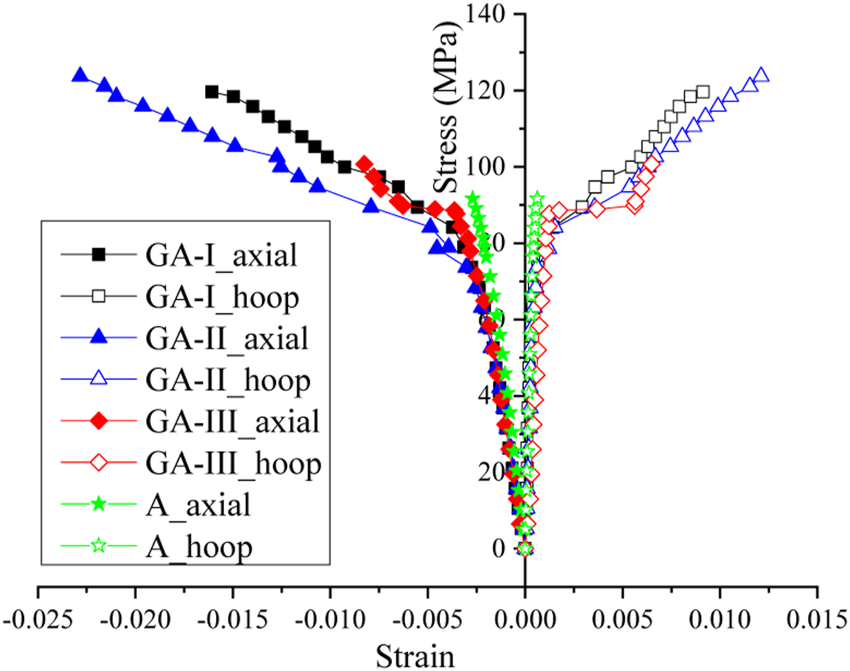
A comparison of the three types of tubes showed that the Series I tube had the best constraining effect on the HSC in the cylinder because the stress-strain relationship had the largest slope in the second linear stage; Although the slope of the Series II tube is smaller than that of the Series I tube in the second linear phase, it has the highest maximum stress and strain. The restraining effect of the Series III tubes on the HSC was not significant, and the stress-strain relationship and maximum stress of this composite structure were similar to those of the unconstrained HSC column. Although the gelling materials in the constituent GFRP tubes also caused a secondary upward trend in the stress-strain relationship for GA-III, the effect was not significant. In summary, the stress-strain relationship of the HSC columns confined by GFRP tube is the same as that of the unconfined HSC column before secondary growth occurs. Therefore, the contribution of the GFRP tube to the axial capacity can be ignored in the numerical analysis.
Effects of expansion agent
As shown in Figure 7(a), the maximum bond strength of specimen B–I was 1.3 times higher than that of A-I, which indicates that the expansion agent can improve the bond strength between the inner wall of GFRP tube and HSC. From Figure 7(b), GB-I has a rapid increase in hoop strain when it reaches about 75% of the maximum stress of B. The stiffness of the structure has been degraded and shows a secondary increase. However, the secondary increase in the stress-strain relationship of GA-I occurs only when the core concrete A reaches near the maximum stress. Therefore, it has been shown that the GFRP tube restrains the B type earlier than the A type. Effect of the expansion agent.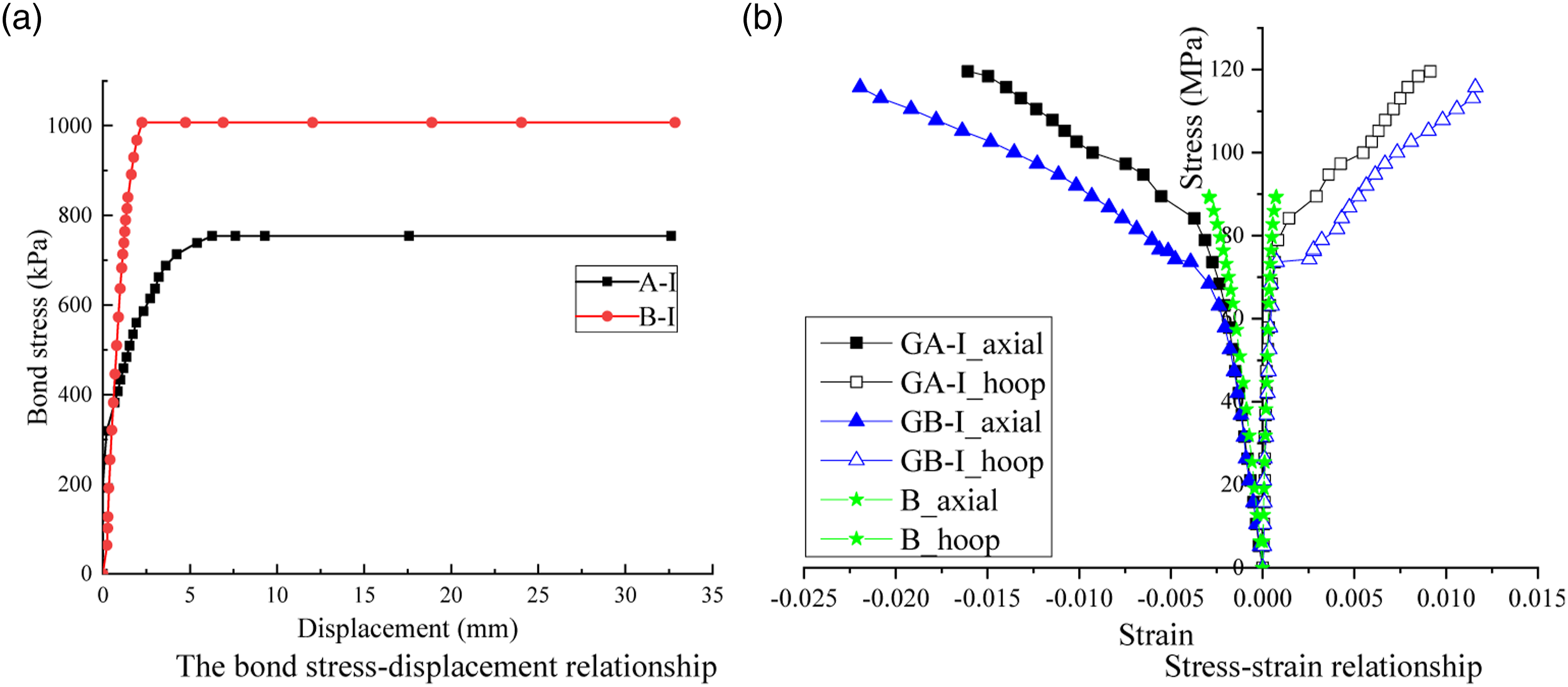
Further analysis revealed that during the solidification of the HSC in the composite column, the expansion agent increased the voids between the aggregates in the B type, thus reducing the compactness of the HSC material and exerting pressure on the lateral direction of the GFRP tube material. Therefore, the maximum push-out stress of B–I was greater than that of A-I, and the maximum strain of GB-I was 1.4 times that of GA-I. The HSC column constrained by GFRP tube increases with the axial load, the voids between B type aggregates decreases, and the lateral deformation of HSC increases. Since the annular confinement of GFRP material is limited, so the maximum stress of GB-I is lower than that of GA-I. In summary, the expansion agent reduces the load-bearing capacity of the composite structure, but improves the ductility and interfacial adhesion.
Effect of loading mode
From Figure 8, the hoop strain of HA-I was larger than that of GA-I, and the axial strain increased by about 45%. This result indicated that under the same axial compression load, the hoop effect of GFRP tube on HSC in composite column with core concrete section compression was more significant than that of the full section compression specimen. Further analysis shows that the GFRP tube in GA-I was not only subjected to hoop restraint stress, but also to axial compressive stress, so that the GFRP tube suffers material damage due to insufficient axial compressive bearing capacity, which affects its hoop restraint capacity against HSC. Compared with GA-I, GFRP in HA-I was only stressed in the circumferential direction, so the load-bearing capacity is higher. Stress-strain relationship of loading mode.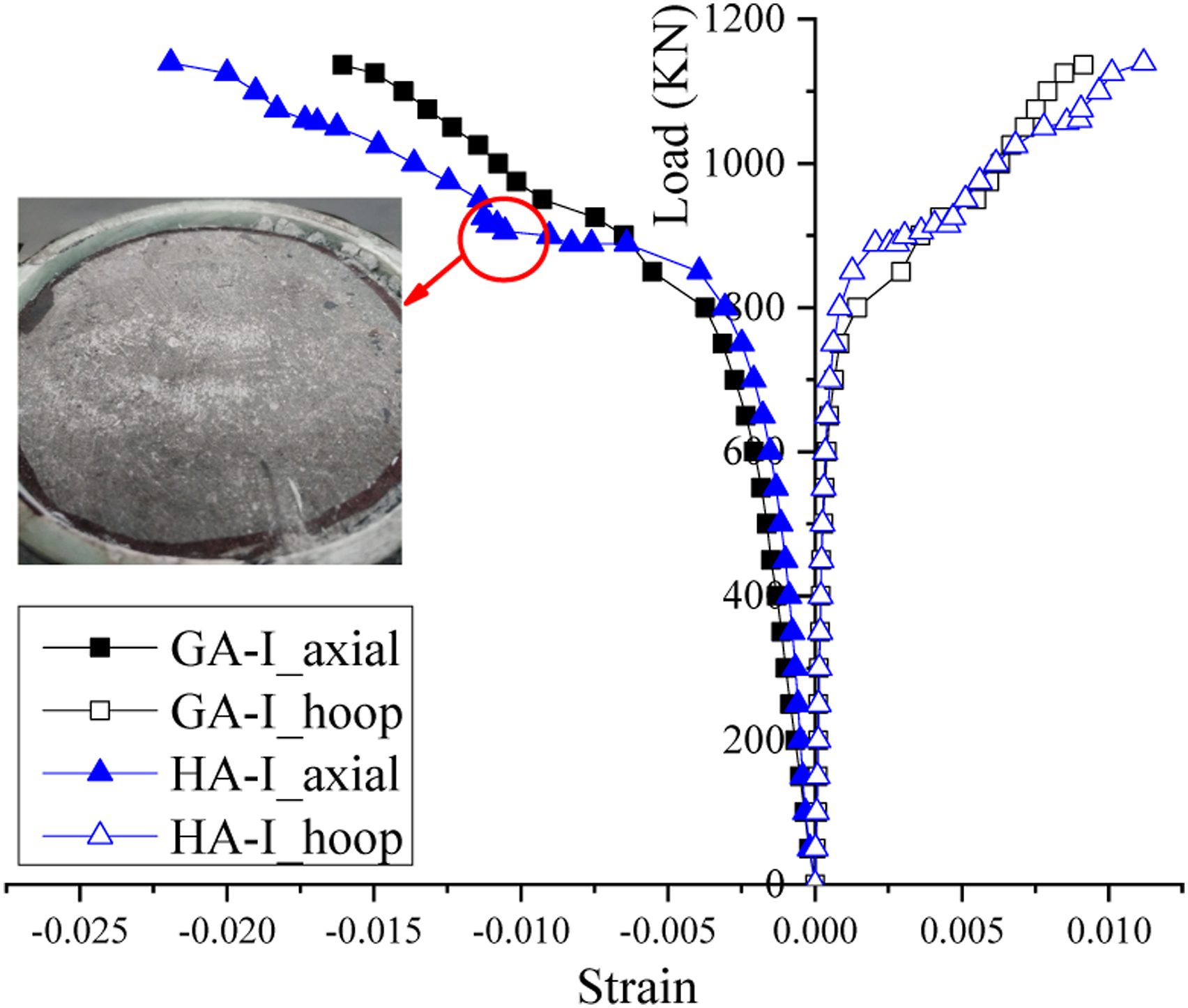
Discussion
There were two failure modes of the composite columns. One of the failure modes is that the GFRP fibers were severely damaged when the structure failed, and many circumferential fibers were broken at the main crack, such as series I and II. This indicates that GFRP tube has a significant strengthening effect on HSC. The other is that GFRP tube has no significant strengthening effect on HSC, and the resin material in the middle of the tube tears along the axial direction when the structure fails, such as Series III. Compared with HSC, the ultimate load capacity of HSC columns reinforced with Series I and II GFRP was increased by 150%.
Both GFRP tube and HSC show brittle failure under axial compression, and the ultimate strains of the two materials were small. During the loading process, the stress-strain relationship of the two materials shows almost linear variation, and there is no significant plastic deformation stage. After reaching the maximum strength, the specimen was destroyed without any failure characteristics, which is not an ideal member in the space truss. However, the combination of GRP tube and HSC significantly improved the ultimate strength and ductility of the composite structure, and the stress-strain curve of the composite structure showed bilinear growth. This behavior indicates that the deformability and brittleness of the composite structure have been significantly improved. Self-compacting HSC technology could avoid the problem of concrete casting in GFRP tube, the expansion agent technology has been improved the bonding properties of composite sections. Therefore, HSC columns limited by Series I and II GFRP could achieve a combined structure with high load-bearing capacity and high deformation, which is an ideal component to bear axial pressure in space truss.
Analytical modeling
GFRP constraint response
Test results of the specimens.
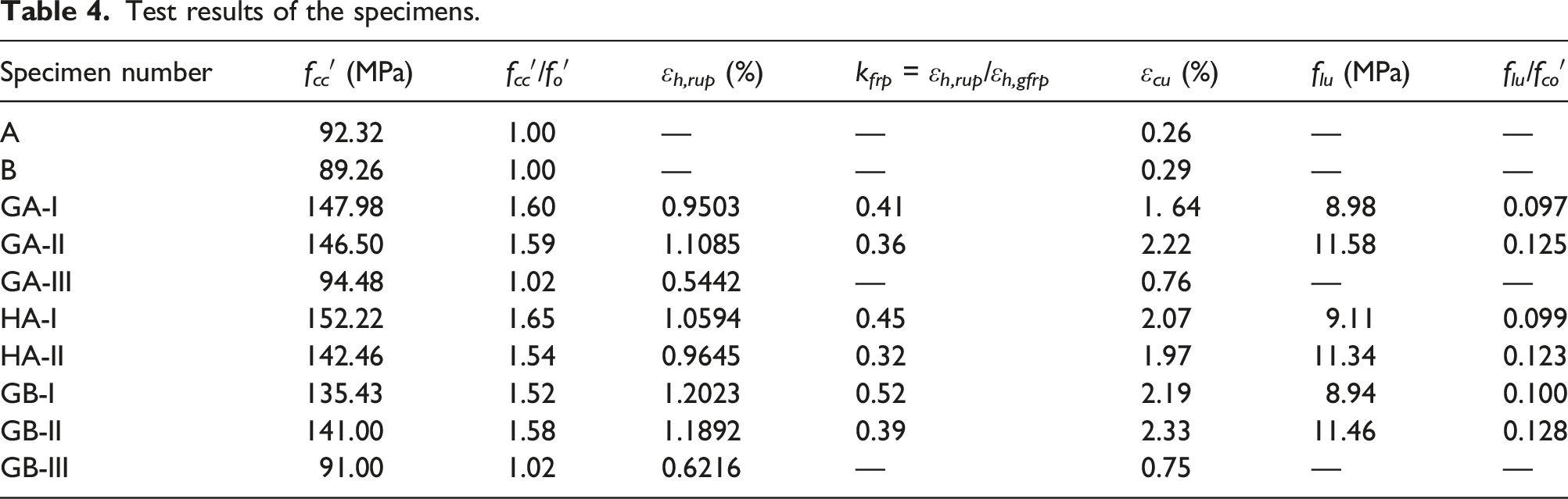
As expected, GFRP tubes ruptured before reaching the tensile strengths of the empty tube test. Such rupturing was typically attributed to the tube curvature and nonuniform expansion of the core (Teng and Lam, 2004). In this test, k frp was 0.46 for specimen I, and 0.37 for specimen II. Compared to unconfined concrete, the ultimate strength of specimens I and II was increased by approximately 1.5 times. However, the ultimate compressive strength of the III specimens was equivalent to that of a without FRP confinement, as shown in Table 4. This result indicates that the III series FRP tube does not confine the concrete in the tube.
Ultimate strength and strain models for HSC confined by GFRP tube
As reported by Lam and Teng (2004), the improvement degree of FRP on concrete performance was related to the thickness and type of FRP. Therefore, the theoretical calculation model was usually based on the constraint effect of unconstrained concrete and FRP on concrete, and obtained by regression analysis of test data under different constraint conditions. The general expression of ultimate strength and strain of this model was as follows (Ma et al., 2020): Prediction models for GFRP confined HSC.

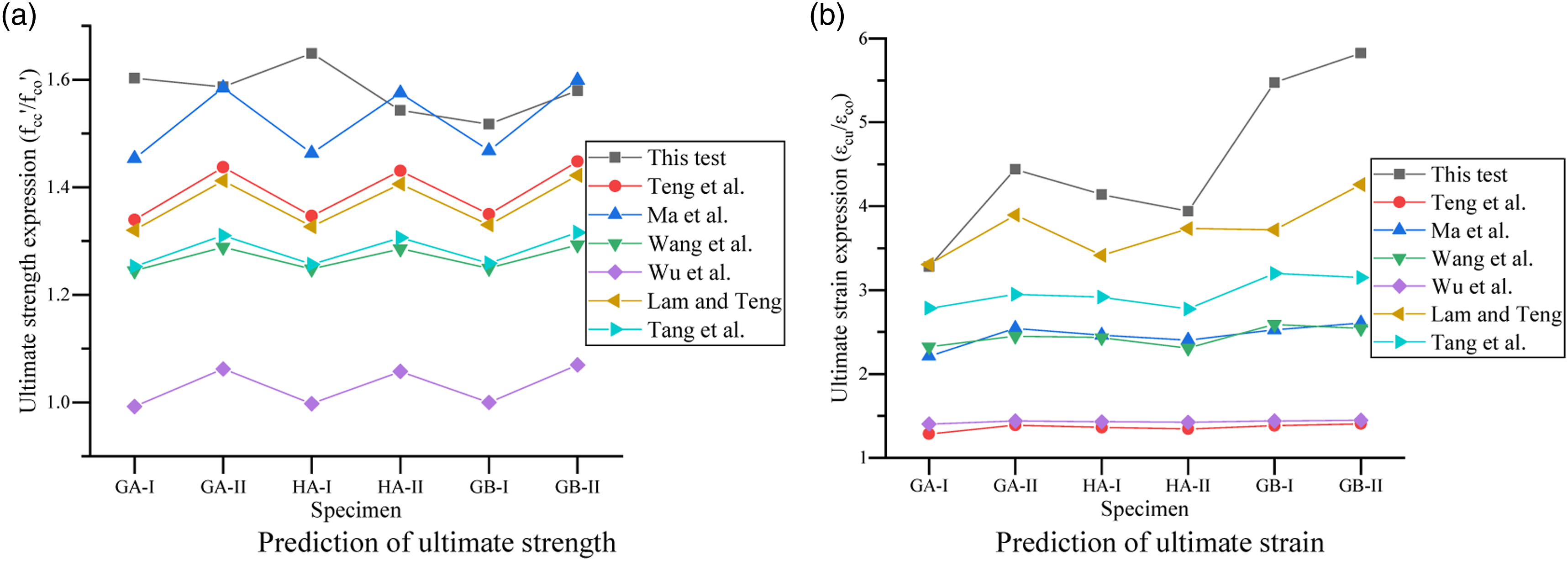
From Figure 9, the variation trends of ultimate strength and strain of different models were consistent, but none of them could accurately predict the test results of GFRP confined HSC. Although the model of Ma et al. and Lam et al. shows high accuracy in the ultimate strength and strain, respectively, the results were smaller than the test values. In the above method, there was no connection between the model of ultimate strength and strain, so in this study, the model with high prediction accuracy was combined into the model suitable for GFRP confined HSC, which was expressed as:

Stress–strain model
According to the test results, the stress-strain relationship of the composite structure shows a bilinear growth, so the bilinear model was used to simulate the stress-strain relationship. Zohrevand and Mirmiran (2013) studied the stress-strain model of FRP-confined concrete and found that Teng’s bilinear model (Teng et al., 2009) was closest to the true value. Therefore, the analytical modeling in this study was based on Teng’s model for GFRP confined concrete, which is as follows: Comparison of predicted stress-strain responses.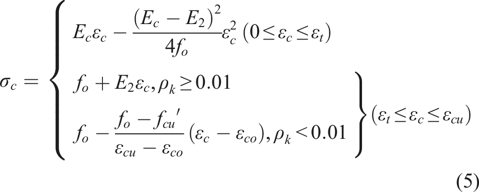

From Figure 10, there were no significant differences in the slope of the first segment of the stress-strain curves between the test results and Teng’s model. However, there were significant differences in the slope, ultimate stress, and strain of the second segment. Therefore, the recalibrated Teng’s model cannot be directly used to predict the stress-strain relationship of the self-compacting micro-expansive HSC short columns. Although the modified Teng’s model could not accurately predict the stress-strain relationship of each specimen, the overall trend was approximately the same, which verified the feasibility of the modified method.
It should be noted that obtaining accurate models must be combined with regression analysis of a large amount of data. However, the current data on GFRP-confined self-compacting micro-expansive HSC was limited, so it was not possible to obtain the more accurate model, and relevant research will be completed in further work.
Conclusions
A composite column with high strength concrete confined by GFRP tube was proposed. The effects of GFRP confined self-compacting micro-expansive HSC were investigated by testing the short columns of 48 specimens under uniaxial compression, focusing on the influences of the formation process, the concrete expansion agent, and the stress mode. The test results were compared with Teng’s confinement models. Based on the test results and analytical modeling, the following conclusions can be drawn. 1. Series I and II GFRP confined HSC specimens failed with GFRP tube rupture at or near mid-height and GFRP fiber rupture. The different loading modes had a negligible effect on the ultimate capacity of the GFRP confined HSC. Under the confinement of the GFRP tube, an increase in confinement pressure increases the confinement effectiveness in HSC at a higher rate than that expected for conventional concrete. However, Series III has no confining effect on the core concrete. 2. Although the expansion agent affected the compactness of the concrete material, resulting in a decrease in the ultimate stress and an increase in the ultimate strain of the material, it improved the interfacial bonding and structural deformation capability of the structure. The maximum strain of the composite column was about 1.4 times that of the column without expansion agent. 3. Teng’s model could not be used directly to predict the stress-strain relationship of the self-compacting micro-expansive HSC columns. The modified model could provide reasonable predictions of ultimate strength, ultimate strain, and stress-strain relationship for GFRP-confined self-compacting micro-expansive HSC specimens. In addition, expansion of the current confined HSC test database will allow further verification of the proposed model.
Footnotes
Declaration of conflicting interests
The author(s) declared no potential conflicts of interest with respect to the research, authorship, and/or publication of this article.
Funding
The author(s) disclosed receipt of the following financial support for the research, authorship, and/or publication of this article: This work was partly supported by the Natural Science Foundation of Hunan Province (Grant no. 2020JJ4313) and the Hunan Province Innovation Platform Open Foundation for University (Grant no. 19K033) which are gratefully acknowledged.
