
Abstract
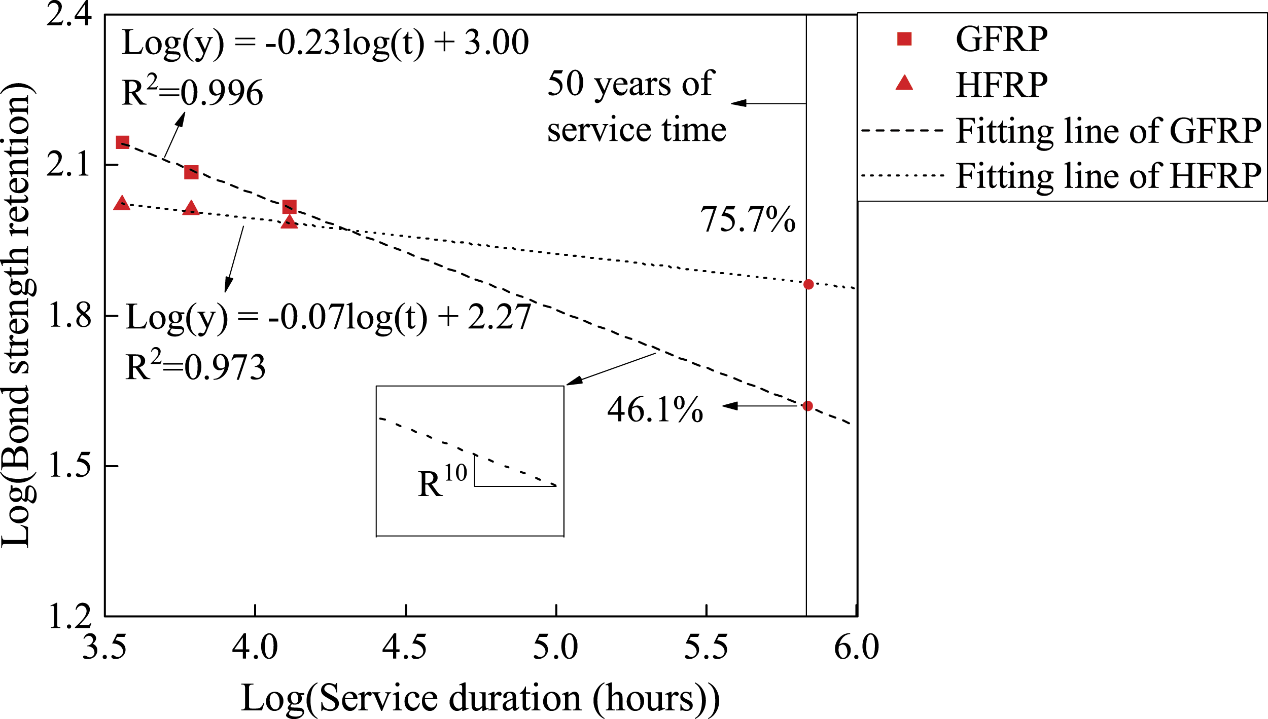
Glass-fiber-reinforced polymer (GFRP) bars have been widely used as a reinforcement in concrete, and glass fibers are susceptible to reacting with alkali ions in concrete pores. Thus, carbon fibers are wrapped around GFRP bars to produce carbon/glass hybrid fiber-reinforced polymer (HFRP) bars so as to promote the durability of the internal GFRP bars in concrete. This work studies the durability of the interfacial bond between GFRP bars/HFRP bars and concrete using pullout tests. The specimens are tested after immersion in distilled water for 0, 150, 255, and 544 days. The failure of the GFRP bar–concrete composite is due to damage to the GFRP bar, while the HFRP bar–concrete composite fails because of a combination of the scratching of the HFRP bar and the failure of the concrete. Both HFRP and GFRP bars are scratched as the immersion period extends. Further, the strength of the bond between the HFRP bar and concrete is lower than that of the bond between the GFRP bar and concrete, while the bond stiffness of the HFRP bar–concrete composite is higher than that of the GFRP bar–concrete composite. The bond strength of the HFRP bar–concrete and GFRP bar–concrete composites increases in the early immersion periods but decreases after 544 days of immersion in water. The retention of the bond strength of the HFRP bar–concrete composite is superior to that of the GFRP bar–concrete composite. The carbon fiber coat is proven to improve the durability of the bond between HFRP bars and concrete in water. A formula for predicting the bond strength of HFRP bar–concrete and GFRP bar–concrete composites in water is also developed. Finally, the modeling results demonstrate that the bond strength retention of the HFRP bar–concrete and GFRP bar–concrete composite is 76% and 46% after 50 years of service time, respectively.
Keywords
Introduction
Glass-fiber-reinforced polymer (GFRP) bars have been widely employed to enhance the durability of concrete structures (Benmokrane et al., 2018; Xian et al., 2022; Zhang et al., 2020) and are used as built-in reinforcing bars in contact with concrete. The pH value of the concrete pore solution ranges from 12.5 to 13.0 (Behnood et al., 2016), and GFRP bars embedded in concrete react with alkali ions, which can deteriorate the mechanical properties of the GFRP bars (Lu et al., 2020). Carbon fiber exhibits a better resistance to alkali ions than glass fiber, and the increase of the production of carbon fiber results in the reduction of the cost of the carbon fiber. An alternative is to wrap a layer of carbon fibers on the outer layer of glass fibers to form a carbon/glass hybrid fiber-reinforced polymer (HFRP), and it can prevent them from contacting OH– ions. Hence, the carbon fiber coat of the carbon/glass HFRP bars can significantly improve the durability of the internal GFRP bars in an alkaline solution (Pan and Yan, 2021). The performance of concrete structures reinforced with FRP bars depends on the bond between FRP bars and concrete. However, the effects of the carbon fiber coat on the durability of the bond between HFPR bars and concrete is still unclear.
The alkaline solution significantly influences the interfacial bond performance of GFRP bar–concrete composites (Micelli and Nanni, 2004). For example, the strength of the interfacial bond between GFRP bars and concrete decreases by 23% in an alkaline solution after 1500 h (Tang et al., 2012). Further, the degradation of the interfacial bond between GFRP bars and concrete intensifies as the immersion time extends. For instance, the strength of the interfacial bond between glass-fiber-reinforced polymer bars and concrete drops by 5.49% and 16.0% after 720 and 2160 h of immersion in an alkaline solution (Altalmas et al., 2015). It is reported that the strength of the bond between GFRP bars and concrete equals 15.0, 14.4, and 14.1 MPa after 60, 120, and 180 days of immersion in 23°C tap water respectively (Robert and Benmokrane, 2010).
Moreover, raising the pH of the immersion solution intensifies the degradation of the interfacial bond between GFRP bars and concrete. Abbasi and Hogg (2005) examined the durability of the bond performance of GFRP bar–concrete composites using pullout tests. Their results showed that the interfacial bond strength declined to 16.4 and 15.1 MPa after 240 days of immersion in distilled water and alkali solution respectively.
The performance degradation of the interfacial bond between GFRP bars and concrete in an alkaline environment results from the degradation of the GFRP bars (Lee et al., 2012). The GFRP bars in concrete in distilled water are in contact with the alkaline pore solution and are more susceptible to degrading than the GFRP bar in concrete in seawater (Guo et al., 2018). The water molecules and OH– ions hydrolyze the resin matrix, followed by forming the microcrack. The concrete pore solution migrates through formed microcracks, and is in contact with the glass fiber (Coomarasamy and Goodman, 1999; Chin et al., 2010). The free hydroxyl ions react with SiO2 in the glass fibers, etching the fiber surface. Afterward, the hydrolysis of the resin matrix and the erosion of the reinforcing fibers deteriorate the fiber–resin interface, thereby affecting the macroscopic mechanical properties of GFRP bars (Chen et al., 2007). Moreover, it is reported that the surface of the GFRP bars deteriorates more severely than their inside part (Wang et al., 2018).
An HFRP bar consists of a GFRP bar coated with a carbon fiber layer. It is reported that carbon-fiber-reinforced polymer (CFRP) has better anticorrosive properties than glass-fiber-reinforced polymer in alkaline and hygrothermal environments (Pan and Yan, 2021; Al-Jelawy and Mackie, 2020; Al-Jelawy, 2013; Guo et al., 2023). Furthermore, the durability of the interfacial CFRP bars–concrete bond is superior to that of the interfacial GFRP bars–concrete bond (Toumpanaki et al., 2020; Micelli and Nanni, 2004). For example, the retention of the interfacial bond strength of GFRP bars–concrete and CFRP bars–concrete composites is 80.4% and 92.9% respectively, after 90 days of immersion in water (Davalos et al., 2008). However, CFRP bars are more expensive than GFRP bars. Thus, an alternative is to wrap a layer of carbon fibers on the outer layer of glass fibers to form a carbon/glass HFRP, taking the cost and resistance to alkali into account. For instance, wrapping a carbon fiber coat around an internal GFRP bar reduces the diffusion coefficient by 50%, 80%, and 12% in an alkaline solution at a temperature of 21, 40, and 60°C respectively and delays the degradation of the mechanical properties of the GFRP bar (Pan and Yan, 2021; Benmokrane et al., 2017).
The present paper investigates the performance evolution of the interfacial bond between an HFRP bar and concrete in water. Further, the bond performance of the GFRP bar–concrete composite is compared with that of the HFRP bar–concrete composite. The mechanism for the effects of the wrapped carbon fiber on the deterioration of the interfacial bond between the HFRP bar and concrete is also examined, and the long-term performance of the interfacial bond of the HFRP bar–concrete and GFRP bar–concrete composites is predicted.
Experimental procedures
Raw materials
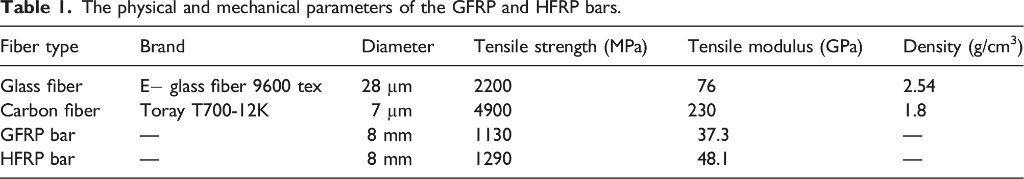
This work adopted GFRP and HFRP bars. Figure 1(a) shows the morphology of the GFRP and HFRP bars. Both GFRP and HFRP bars were produced by the Harbin Institute of Technology, China, and had a nominal diameter of 8 mm. Bisphenol A and methylhexahydrophthalic anhydride were employed as the resin and hardener of the matrix of FRP bars. Figure 1(b) shows manufacturing process of HFRP bars (Pan and Yan, 2021). Table 1 lists the characteristics of the glass and carbon fibers, which provided by the manufacturer (Pan and Yan, 2021). The tensile test of the FRP bars were carried out according to standard GBT 30022–2013, and the tensile properties of FRP bars are listed in Table 1. (a) The morphology of the GFRP and HFRP bars (unit: mm) and (b) the manufacturing process of HFRP bars. The physical and mechanical parameters of the GFRP and HFRP bars.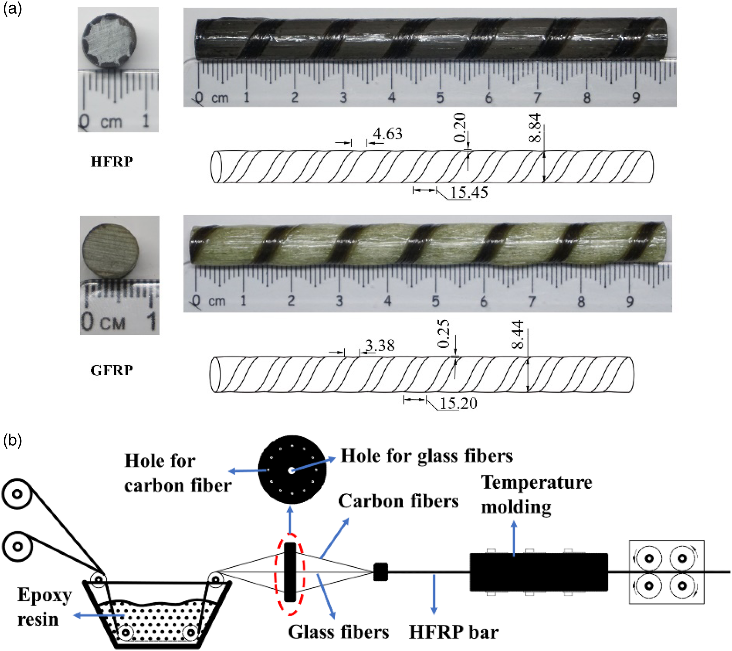
The concrete comprised water, PO 42.5 portland cement, sand, and gravel with a mass ratio of 0.44:1.00:1.31:2.78. Cubic specimens with the dimensions 100 mm × 100 mm × 100 mm were tested after 28 days of curing at room temperature, and the compressive strength of the concrete measured 47.5 MPa.
Exposure conditions
The FRP bar–concrete composites generally service under hygrothermal conditions. The water immersion in distilled water was adopted to simulate the service conditions, and accelerated the degradation of the FRP bar–concrete composites. The specimens were exposed to distilled water and immersed for 150, 255, and 544 days. After the specimen was removed from the water, pullout tests were performed on the FRP bars within 48 h. The environmental temperature was the mean annual temperature in Hangzhou, China, and measured 21°C. The distilled water was poured into chamber every month owing to the evaporation of the water.
Specimen preparation
The present study prepared 24 pullout specimens: 12 GFRP bar–reinforced concrete specimens and 12 HFRP bar-reinforced concrete composites. Three specimens were tested at each intervals. Figure 2 shows the dimensions of the prepared FRP bar–concrete composites according to standard ACI 440.3R-04 (ACI440.1R-15, 2015). Referring to standard ACI 440.3R-04 and the recommendation of Sena-Cruz et al. (ACI440.1R-15, 2015; Mazaheripour et al., 2013), the bond length of FRP bars–concrete composites was five times the nominal diameter of the FRP bars. The diagram of the prepared FRP bar–concrete composites (unit: mm).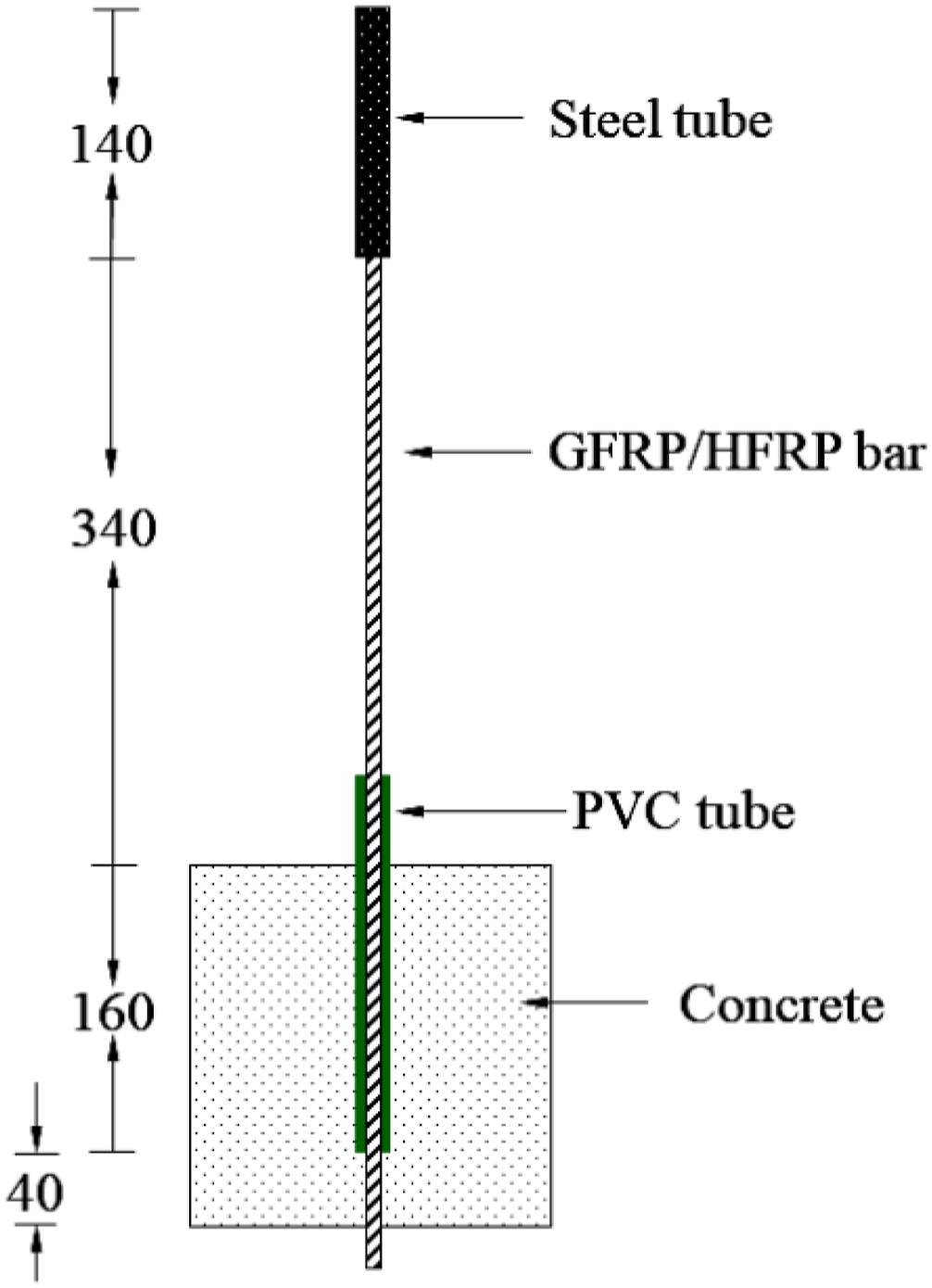
Pullout tests
Figure 3 illustrates the pullout test setup developed by the Laboratory for FRP Composites and Structures (LFCS), Harbin Institute of Technology, China. The applied load was controlled using a jack, and three linear variable differential transformers (LVDTs) recorded the displacement. The first LVDT measured the displacement of the free end of the FRP bar on the surface of the concrete, and the second measured the relative displacement between the concrete and the device. The third LVDT also recorded the displacement of the loading end of the GFRP bar. A 3820H acquisition instrument with a recording frequency of 1 Hz collected the data of the LVDTs and the load. An (a) image and (b) schematic of the pullout test setup.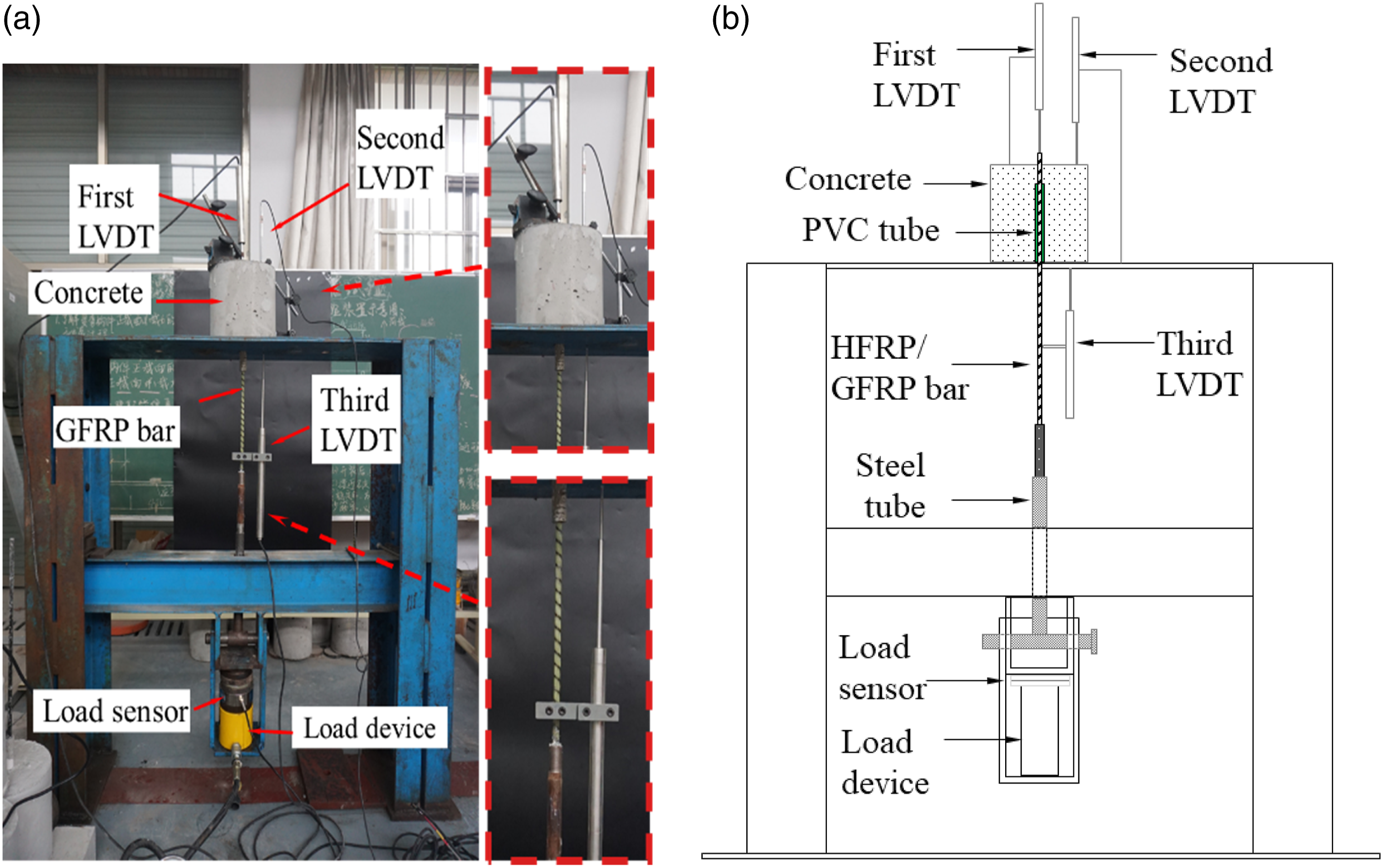
Scanning electron microscopy (SEM)
A scanning electron microscope (Zeiss Gemini Scanning Electron Microscopy (SEM) 500, Germany) analyzed the surface of the FRP rebars after the pullout tests.
Results and discussion
Compressive strength of concrete
The compressive strength of concrete.
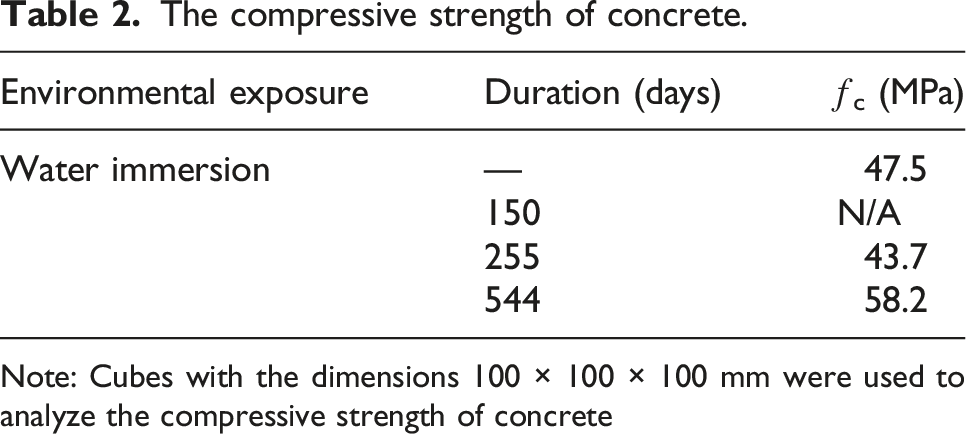
Note: Cubes with the dimensions 100 × 100 × 100 mm were used to analyze the compressive strength of concrete
Failure mode
Figure 4 shows the failure mode of the FRP bar–concrete composites after the pullout test. Figures 4(a) and (b) shows the surface morphology of the control specimens after the pullout test. The interfacial bond of both GFRP bar–concrete and HFRP bar–concrete composites fails. The failure of the GFRP bar–concrete specimen results from the severe scratches of the GFRP bar ribs, while the HFRP bar–concrete specimen fails due to the failure of the concrete around the HFRP bar, indicating that the surface of the GFRP bar damages more severely than that of the HFRP bar, attributed to the higher tensile modulus of carbon fibers than glass fibers. The failure mode of the (a) control HFRP bar, (b) control GFRP bar, (c) HFRP bar after 150 days of immersion, (d) GFRP bar after 150 days of immersion, (e) HFRP bar after 255 days of immersion, (f) GFRP bar after 255 days of immersion, (g) HFRP bar after 544 days of immersion, and (h) GFRP bar after 544 days of immersion.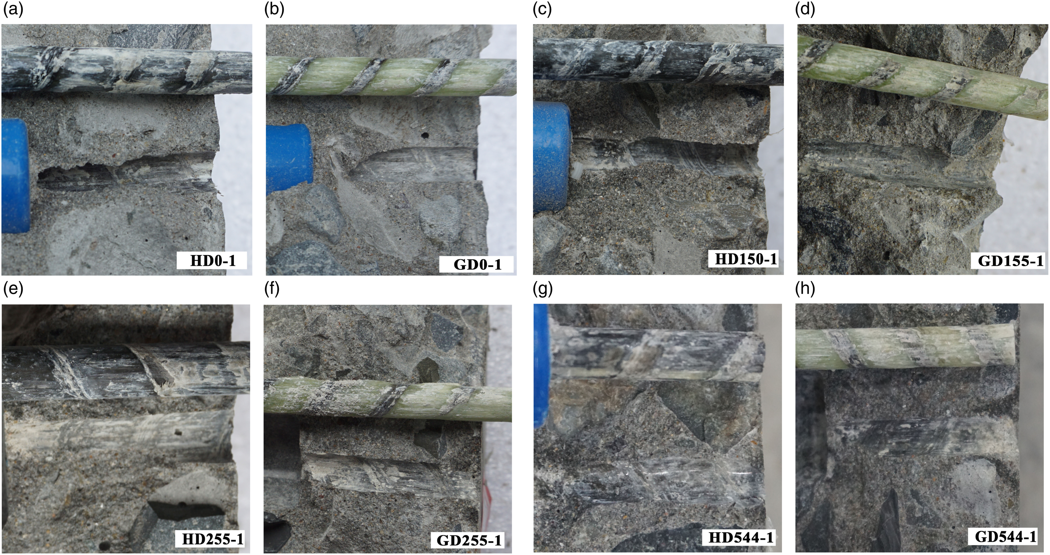
Figure 4(c), 4(e), and 4(g) illustrates the failure mode of the HFRP bar–concrete composites immersed in distilled water for 150, 255, and 544 days respectively. Compared to the control specimens, the aged HFRP bar–concrete specimen fails owing to a combination of the failure of the concrete and the scratching of the HFRP bar. The surface of the HFRP bar scratches more severely as the immersion period extends, causing damage to the HFRP bar due to its water absorption (Pan and Yan, 2021; Refai et al., 2015).
Figure 4(d), 4(f), and 4(h) shows the failure mode of the GFRP bar–concrete specimen immersed in distilled water for 150, 255, and 544 days respectively. The failure modes of the aged specimens are similar to those of the control specimens: they fail due to the scratches of the glass-fiber-reinforced polymer bars. More scratches of the glass-fiber-reinforced polymer bars is found as the immersion time increases. The ribs of the GFRP bars entirely scratch after 544 days of immersion in distilled water in Figure 4(h). The hydrolysis of resin matrix and glass fiber eroded by the OH– ions in the concrete pore solution (Al-Jelawy and Mackie, 2021; Wang et al., 2017), and it causes the weak bond between glass fiber and resin matrix.
Comparing the failure modes of the interface of the GFRP bar–concrete and HFRP bar–concrete composites reveals that the failure of the HFRP bar–concrete specimen is controlled by a combination of the deterioration of the HFRP bar surface and the failure of the concrete around the HFRP bar. In contrast, the GFRP bar–concrete composite fails because of the deterioration of the surface of the GFRP bar, implying that the GFRP bar is delaminated more severely than the HFRP bar in the concrete immersed in water.
Microstructure analysis
Figure 5 displays the scanning electron microscopy images of the HFRP bar surface after the pullout test, and Figure 5(a) shows the SEM image of the surface of the control HFRP bar. A large amount of resin matrix is found, but the fiber is perfectly protected, which indicates that the control HFRP bar–concrete specimen fails due to the failure of the concrete around the HFRP bar. Figure 5(c) shows the SEM image of the surface of the HFRP bar after 544 days of immersion in distilled water. The resin coating of some carbon fibers is removed, and the resin matrix is scratched by the concrete, which implies that the interfacial bond failure of the HFRP bar–concrete composite results from a combination of the failure of the concrete and the scratching of the HFRP bar. The SEM images of the surface of the (a) control HFRP bar, (b) control GFRP bar, (c) HFRP bar immersed in distilled water for 544 days, and (d) GFRP bar immersed in distilled water for 544 days.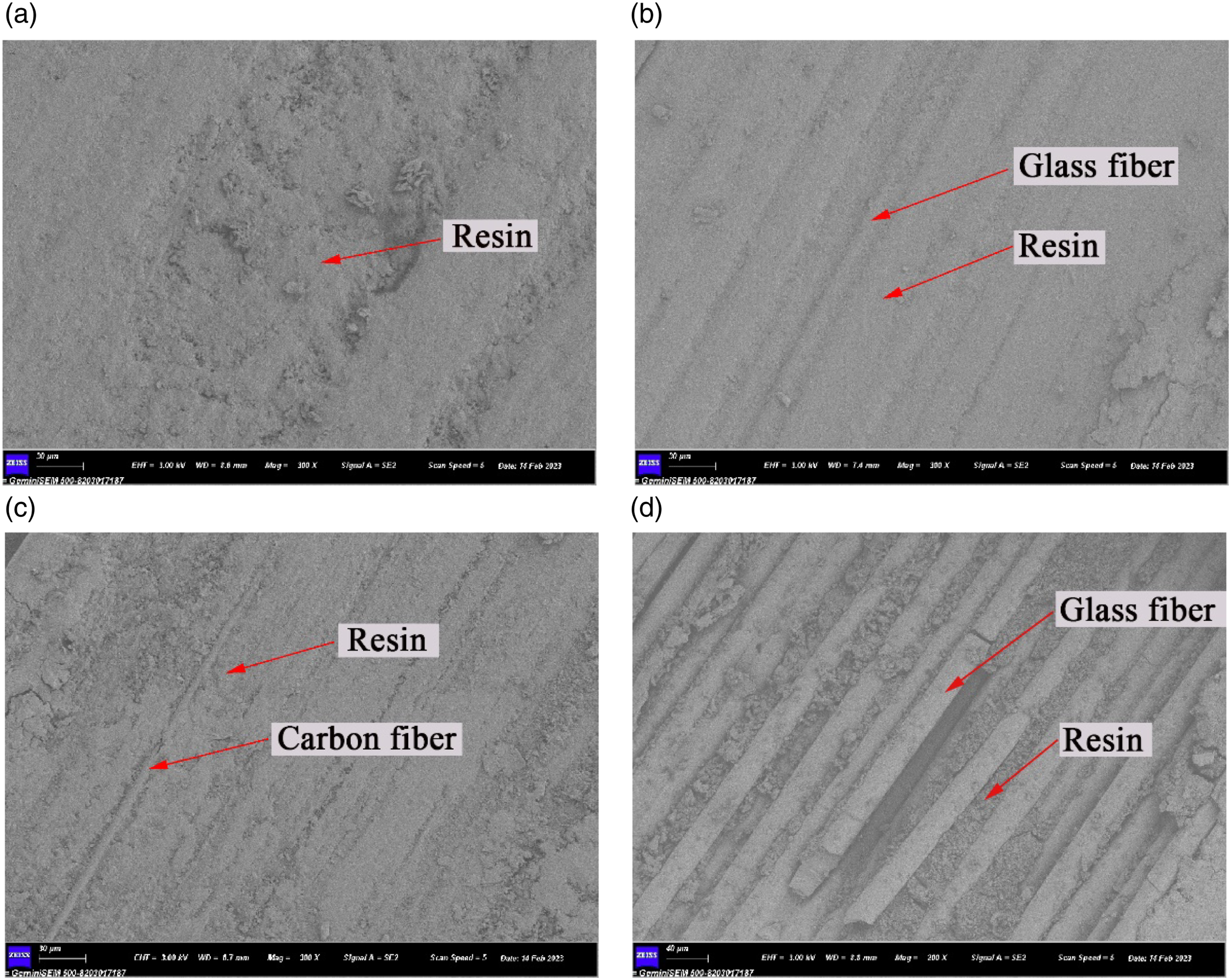
Figure 5(b) shows the SEM image of the surface of the control GFRP bar. The control GFRP bar–concrete specimen fails due to the peeling of the surface resin, and some glass fibers are found in Figure 5(b). Figure 5(d) shows the SEM image of GFRP surface after 544 days immersion in distilled water. Compared to the control specimens, a more glass fibers are obviously found after 544 days of immersion. The aged GFRP bar–concrete specimen fails owing to the weak bond between glass fiber and resin matrix.
Bond stress–slip response
The distribution of bond stress along the FRP bar is uniform, and the average stress on the bond of the FRP bar–concrete is defined as:
Figure 6 delineates the bond stress–slip curve of the FRP bar–concrete composite at the loading and free ends. The variation in the bond stress with the slip at the loading and free ends of the interface of the HFRP bar–concrete and GFRP bar–concrete composites before and after immersion in distilled water: (a) the bond stress versus the slip at the loading end of the GFRP bar–concrete and HFRP bar–concrete interface without immersion; (b) the bond stress versus the slip at the loading end of the GFRP bar–concrete interface; (c) the bond stress versus the slip at the loading end of the HFRP bar–concrete interface; (d) the bond stress versus the slip at the free end of the GFRP bar–concrete interface; (e) the bond stress versus the slip at the free end of the HFRP bar–concrete interface.

The parameters of the bond stress–slip response of the FRP bar–concrete composites exposed to distilled water.
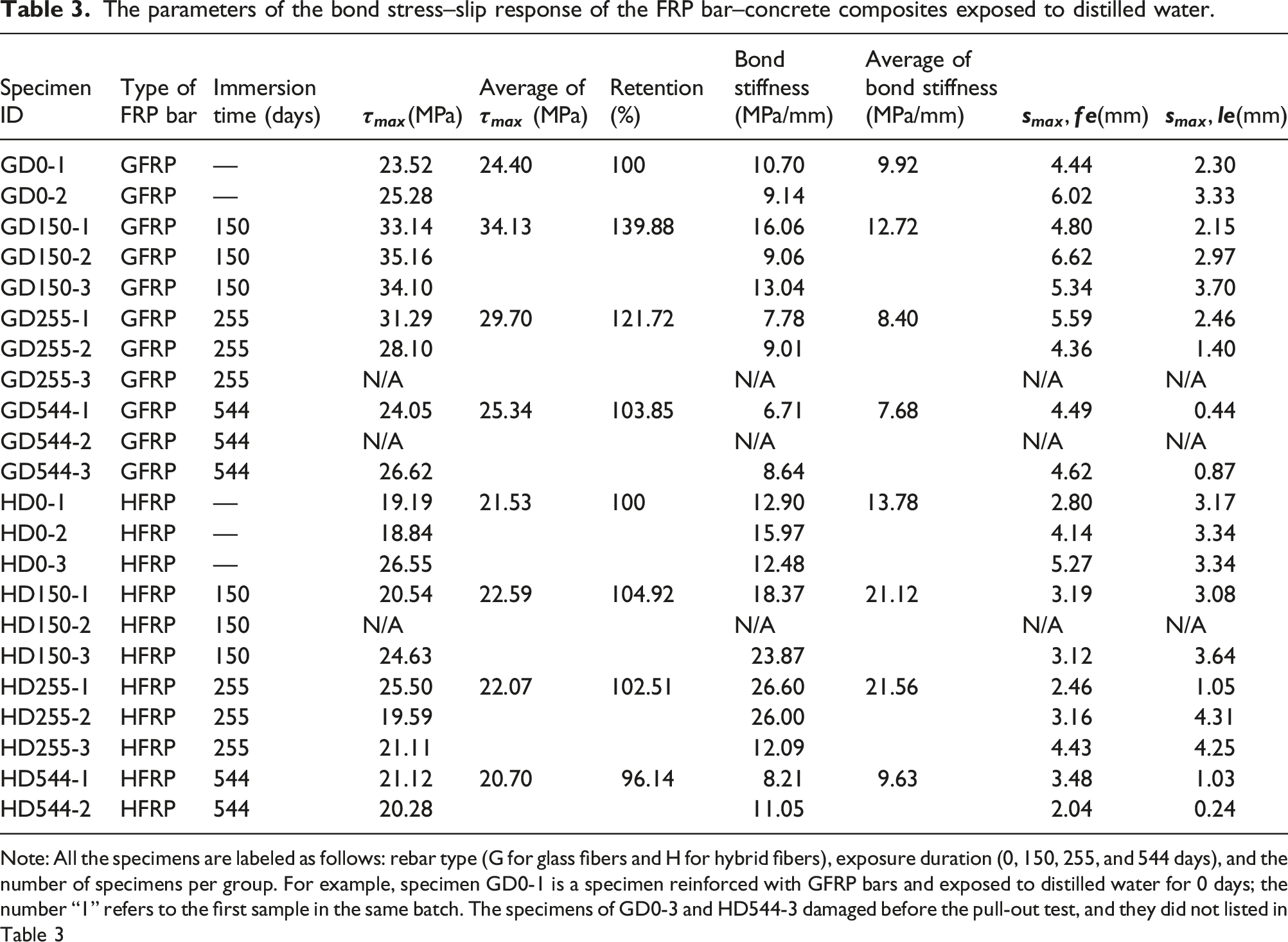
Note: All the specimens are labeled as follows: rebar type (G for glass fibers and H for hybrid fibers), exposure duration (0, 150, 255, and 544 days), and the number of specimens per group. For example, specimen GD0-1 is a specimen reinforced with GFRP bars and exposed to distilled water for 0 days; the number “1” refers to the first sample in the same batch. The specimens of GD0-3 and HD544-3 damaged before the pull-out test, and they did not listed in Table 3
Figure 6 plots the bond stress–slip curve of the FRP bar–concrete specimens. The bond stress linearly increases in the initial stages of the curve, and chemical bonding primarily controls the bond between the FRP bar and concrete in this stage. The bond stress nonlinearly enlarges with further increasing the slip at the loading end due to the loss of the chemical bonding; frictional forces and mechanical interactions control the bond between the FRP bar and concrete. The mechanical interactions mainly result from the interactions between the transverse ribs of the FRP bar and the surrounding concrete (Wang et al., 2020). The bond stress rapidly decreases in the descending stage once it reaches the maximum bond stress. Frictional bonding controls the bond between the FPR bar and concrete in this stage. The curve of the bond stress-slip at the loaded end in Figure 6(b) and (c) are similar to the curve of the bond stress-slip at the free end in Figure 6(d) and (e). The slip at the loaded end is larger than that at the free end under the similar bond stress. The slip at the loaded end includes the tensile deformation of the FRP bar along the bond length.
Effects of water immersion on bond strength of FRP bar–concrete
Figure 7 shows the variation in the bond strength of the FRP bar–concrete composite. In the case of the control specimen, the bond strength of GFRP bar–concrete and HFRP bar–concrete composites are 24.4 MPa and 21.5 MPa, respectively. They are larger than the guaranteed bond strength (e.g., more than 9.6 MPa) recommended by ACI 440.1R–15. It indicates that the HFRP bar is available to reinforce concrete structures. The bond strength of the HFRP bar–concrete composite is 74.8% of that of the GFRP bar–concrete composite. The elastic moduli of the GFRP bar and concrete are similar (Li et al., 2019), which gives rise to the better deformation compatibility of the GFRP bar with the concrete. Thus, the bond strength of the GFRP bar–concrete specimen is higher than that of the HFRP bar–concrete composite. The variation in the bond strength of the GFRP bar–concrete and HFRP bar–concrete composites.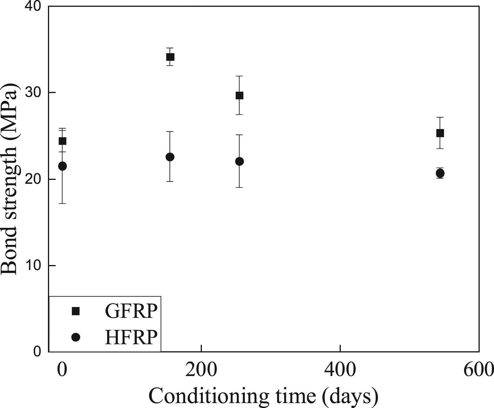
The bond strength of the GFRP bar–concrete composite varies by the immersion period. Compared with the control specimens, the bond strength of the GFRP bar–concrete specimen after 150 days of water immersion increases by 39.9%, while that of the GFRP bar–concrete specimen immersed in distilled water for 544 days only rises by 4.0%. The increase of the GFRP bar–concrete composite results from enhancement of the bond between GFRP bar and concrete owing to the swelling of the GFRP bar in distilled water. It was reported that the volume of GFRP bar expanded after water absorption (Sun et al., 2022). A more extended immersion periods (e.g., 544 days) cause the deterioration of the outside of the GFRP bar (Yu et al., 2021). It causes the reduction of the bond strength of the GFRP bar–concrete specimen immersed in distilled water for 544 days (Gravina et al., 2020).
Regarding the HFRP bar–concrete composites, the strength of the bond between the HFRP bar and concrete increases by 4.9% and 2.5% after 150 and 255 days of immersion respectively, compared to the control specimens. Nevertheless, the bond strength of the HFRP bar–concrete composite declines by 3.9% as the immersion period extends to 544 days. Therefore, the immersion period affects the bond strength of the HFRP bar–concrete composite less significantly than that of the GFRP bar–concrete specimen. Indeed, the carbon fiber coat prevents the internal GFRP bar from swelling, so the bond strength of the HFRP bar–concrete composite is insignificantly influenced by immersion in water.
Effects of water immersion on bond stiffness of FRP bar–concrete
Figure 8 depicts the variation in the bond stiffness of the FRP bar–concrete composite with the immersion time. The bond stiffness of the control GFRP bar–concrete specimen is 61.1% of that of the control HFRP bar–concrete specimen. It is reported that the elastic modulus of the glass fiber is 76 GPa, and that of the carbon fiber is 230 GPa. According to the rule of mixtures (Kretsis, 1987), the tensile stiffness of HFRP bars is higher than that of GFRP bars. The larger the tensile elastic modulus, the higher the bond stiffness of the FRP bar–concrete composite. The variation in the bond stiffness of the GFRP bar–concrete and HFRP bar–concrete composites.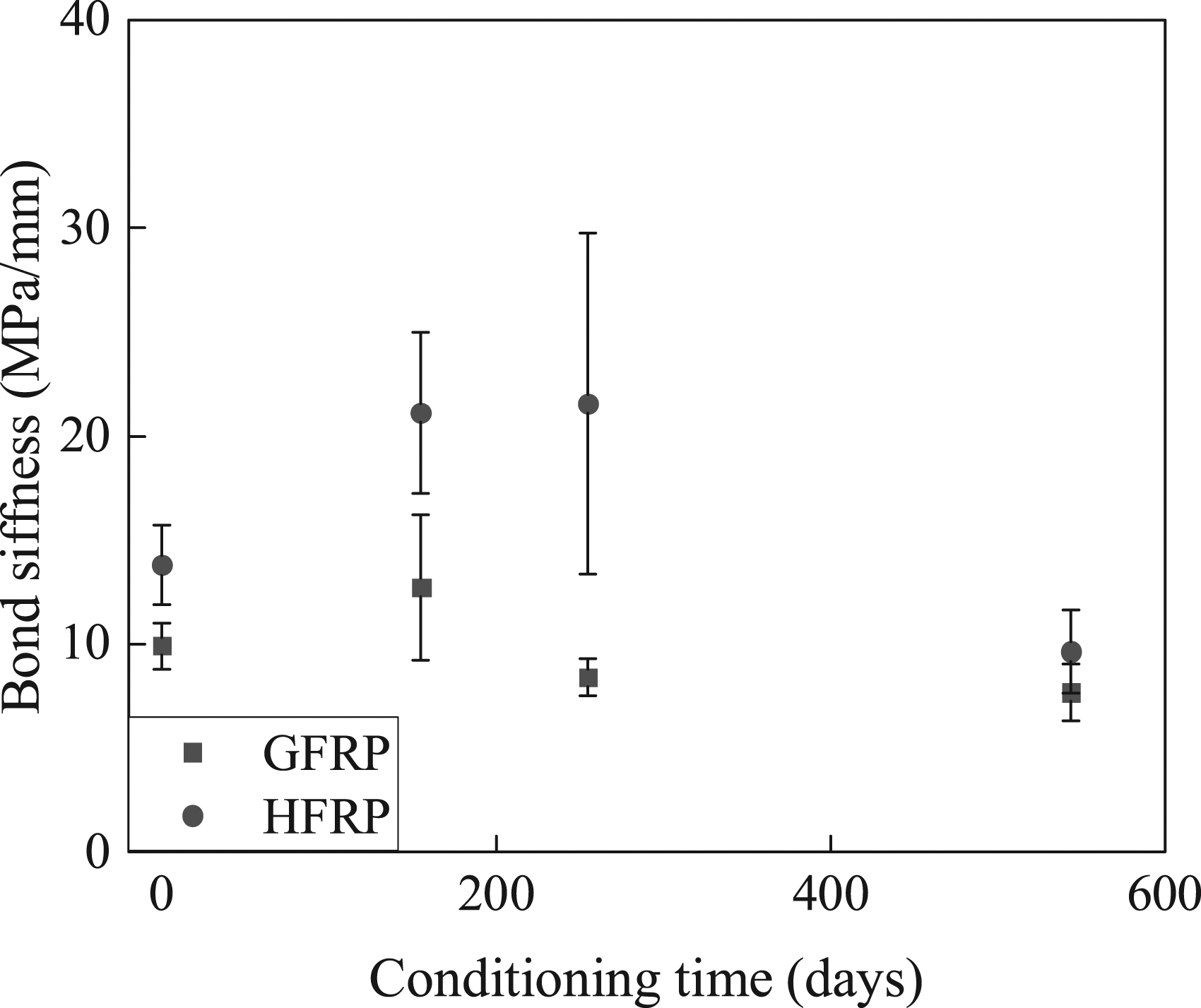
Immersing the GFRP bar–concrete composite in distilled water for 150 days raises its bond stiffness by 28.2%. The bond between the GFRP bar and the concrete depends on the mechanical interactions and frictional forces. The frictional forces increase owing to the swelling of the GFRP bar after water absorption. However, the bond stiffness of the GFRP bar–concrete composite drops as the immersion time further extends. For example, the bond stiffness of the GFRP bar–concrete composite declines by 15.4% and 22.6% after immersion in distilled water for 255 and 544 days respectively, compared to the control specimens. In fact, longer immersion in water deteriorates the GFRP bar owing to the hydrolysis of its resin matrix and the erosion of its glass fiber reacting with hydroxide ions.
The bond stiffness of the HFRP bar–concrete composite immersed in water for 150 and 255 days improves by 53.2% and 43.6% respectively, compared to the control specimens. The carbon fiber coat prevents the internal GFRP bar from swelling, and the frictional forces do not vary. However, the effect of water immersion on damage to the HFRP bar intensifies as the immersion period increases. The bond stiffness of the HFRP bar–concrete composite immersed in distilled water for 544 days is 69.9% of that of the control specimens.
Effects of water immersion on slip of FRP bar–concrete
Figure 9(a) plots the variation of the slip corresponding to the bond strength at the free end ( The variation in the slip of the GFRP bar–concrete and HFRP bar–concrete composites at the (a) free end and (b) loaded end.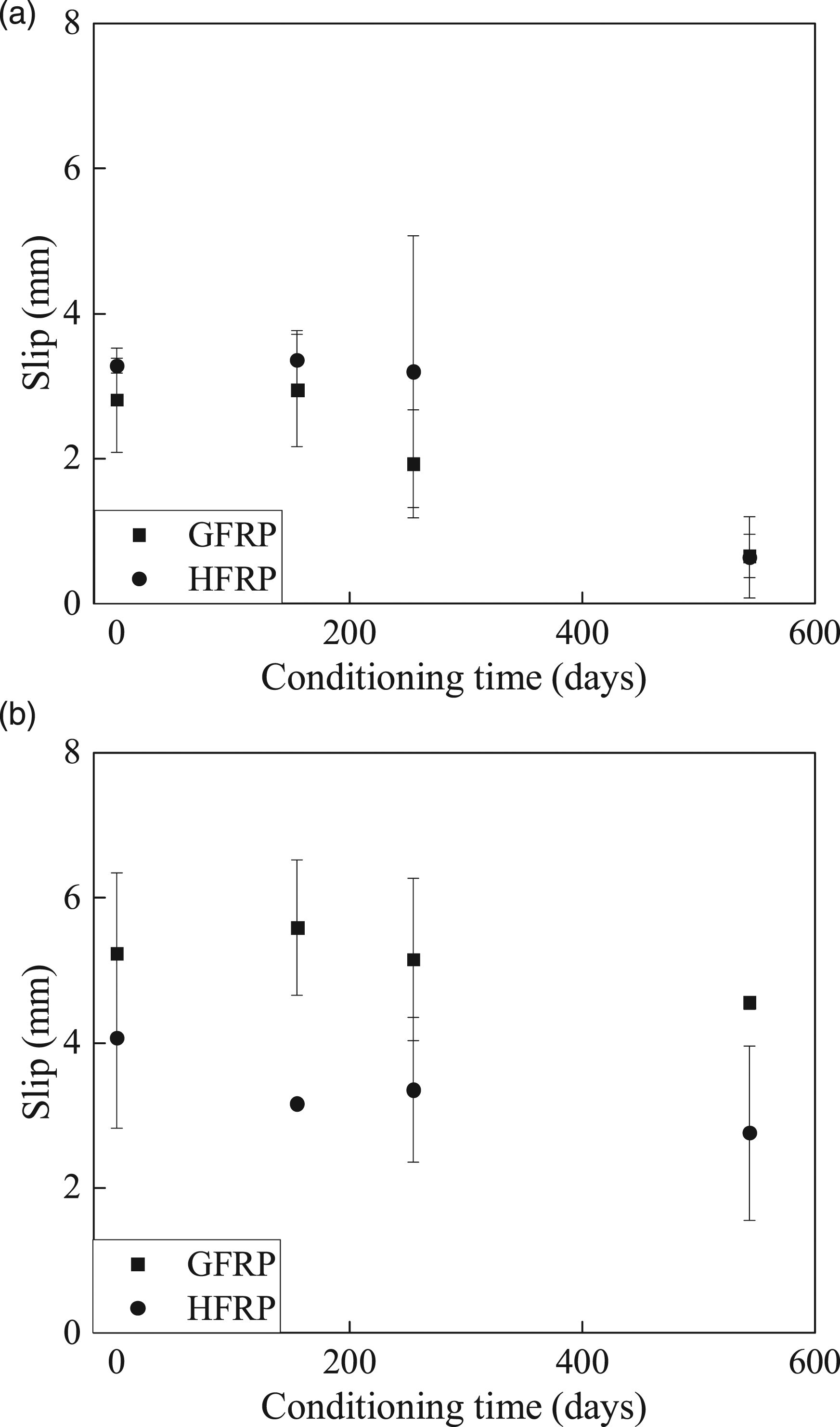
The effect of water immersion on the slip corresponding to the bond strength is insignificant in the initial 255 days of immersion in distilled water. The variation in the slip corresponding to the bond strength of the GFRP bar–concrete and HFRP bar–concrete composites ranges from 4.7% to 31.4% and from 2.4% to 2.44% respectively. Moreover, the slip corresponding to the bond strength of the GFRP bar–concrete and HFRP bar–concrete composites immersed in distilled water for 544 days is only 23.3% and 19.7% of that of the control specimens respectively. The surface deterioration of the FRP bars results in a significant reduction of the slip.
Figure 9(b) plots the variation of the slip corresponding to the bond strength at the loading end (
Predicting retention of long-term bond strength
As discussed above, the degradation of the bond between the FRP bar and concrete depends on the deterioration rate of the FRP bar (Robert and Benmokrane, 2010; Davalos et al., 2008; Liu et al., 2020; Lee et al., 2012). The Arrhenius degradation theory assumes that the rate of degradation of FRPs is accelerated with environmental temperature increasing, and the single dominant degradation mechanism of FRPs does not vary at the exposure duration (Manalo et al., 2020). Equation (3) can predict the long-term properties of fiber-reinforced polymers (Serbescu et al., 2015):
The a and b parameters of the GFRP bar–concrete and HFRP bar–concrete composites.

The bond stress retention of the FRP bar–concrete composites immersed in distilled water at 21°C.


The bond strength retention of the GFRP bar–concrete and HFRP bar–concrete composites after 50 years of service under different environmental conditions.
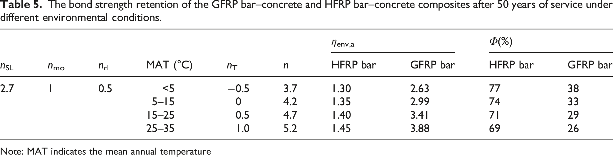
Note: MAT indicates the mean annual temperature
Referring to standard ACI 440.1R–15 (ACI440.1R-15, 2015), we can express the retention of the bond strength of the FRP bar–concrete composite by:
Conclusions
The present paper examined the durability of the interfacial bond of GFRP bar–concrete and HFRP bar–concrete composites in water. From the above results and discussion, the following conclusions could be drawn: • The GFRP bar–concrete specimen failed due to damage to the GFRP bar, which was intensified as the immersion time extended. The HFRP bar–concrete composite failed owing to a combination of the scratching of the carbon/glass hybrid fiber-reinforced polymer bar and the failure of the concrete. The scratches of the HFRP bar increased as the immersion period extended. • The bond strength of the HFRP bar–concrete composite is 74.8% of that of the GFRP bar–concrete composite. Further, the bond strength of both HFRP bar–concrete and GFRP bar–concrete composites increased after 150 days of immersion in distilled water. However, more extended immersion periods reduced the bond strength of both HFRP bar–concrete and GFRP bar–concrete composites. • The bond stiffness of the HFRP bar–concrete composite was higher than that of the GFRP bar–concrete specimen due to a higher elastic modulus of the HFRP bar than the GFRP bar. The bond stiffness of both HFRP bar–concrete and GFRP bar–concrete composites increased within 150 days of immersion in distilled water. Further, water immersion affected the bond stiffness of the HFRP bar–concrete composite more significantly than that of the GFRP bar–concrete specimen. • A model for predicting the bond strength of both HFRP bar–concrete and GFRP bar–concrete composites was developed. The bond strength retention of the HFRP bar– and GFRP bar–concrete composite is 76% and 46% after 50 years of service, respectively.
Footnotes
Author contributions
conceptualization, investigation, project administration, funding acquisition, Yunfeng Pan; methodology, writing—review and editing, Biao Li; formal analysis, investigation, writing—original draft preparation, Gaojie Xu and Yixun Yu.
Declaration of conflicting interests
The author(s) declared no potential conflicts of interest with respect to the research, authorship, and/or publication of this article.
Funding
The author(s) disclosed receipt of the following financial support for the research, authorship, and/or publication of this article: This work was supported by the National Natural Science Foundation of China (grant numbers 51908507, 52278280), the Zhejiang Postdoctoral Foundation (grant number ZJ2022150), and the Zhejiang Provincial Natural Science Foundation (project number LY19E080029).
Data availability
Some or all the data, models, or codes that support the findings of this study are available from the corresponding author upon reasonable request.