
Abstract
The at-ground-structure supports the maglev track on the subgrade segment and receives the subgrade’s equally distributed elastic support to ensure the holding track running of the maglev train. A complicated maglev train-track-at-ground-structure coupled system is produced, negatively affecting the stable operation of the train. To explore the vibration mechanism, an elaborate maglev train-track-at-ground-structure coupled system was established considering active levitation control, and field tests confirmed the reliability of the numerical method. Firstly, the natural frequencies of track-at-ground-structure were investigated. Then, characteristics of this coupled system were examined in terms of its dynamic interaction mechanism, dynamic response characteristics and vibration frequency spectrum distribution. Finally, the vehicle-induced resonance mechanism and anti-vibration methods of the at-ground-structure were analyzed. The results show that the high-frequency vibrations exist in both the F-rail and at-ground-structure obviously, and create varied wavelengths affecting the maglev train’s running stability. The high frequency resonance phenomena easily produce when loading frequency of neighboring levitation forces is near to fundamental frequency of at-ground-structure, and disappears while the two frequencies are avoided.
Introduction
LMS (low-to-medium-speed) maglev transportation offers the benefits of big ascending ability, short turning radius, low vibration, and low noise (Lee et al., 2006). It abandons the typical mechanical contact between the wheel and the rail in favor of a novel levitation operation mode with no mechanical contact (Sun et al., 2022). As a result, it’s critical to guarantee that maglev trains run smoothly by generating adequate electromagnetic levitation force and minimizing rated levitation gap variation as much as feasible (Shi and Cai, 2008).
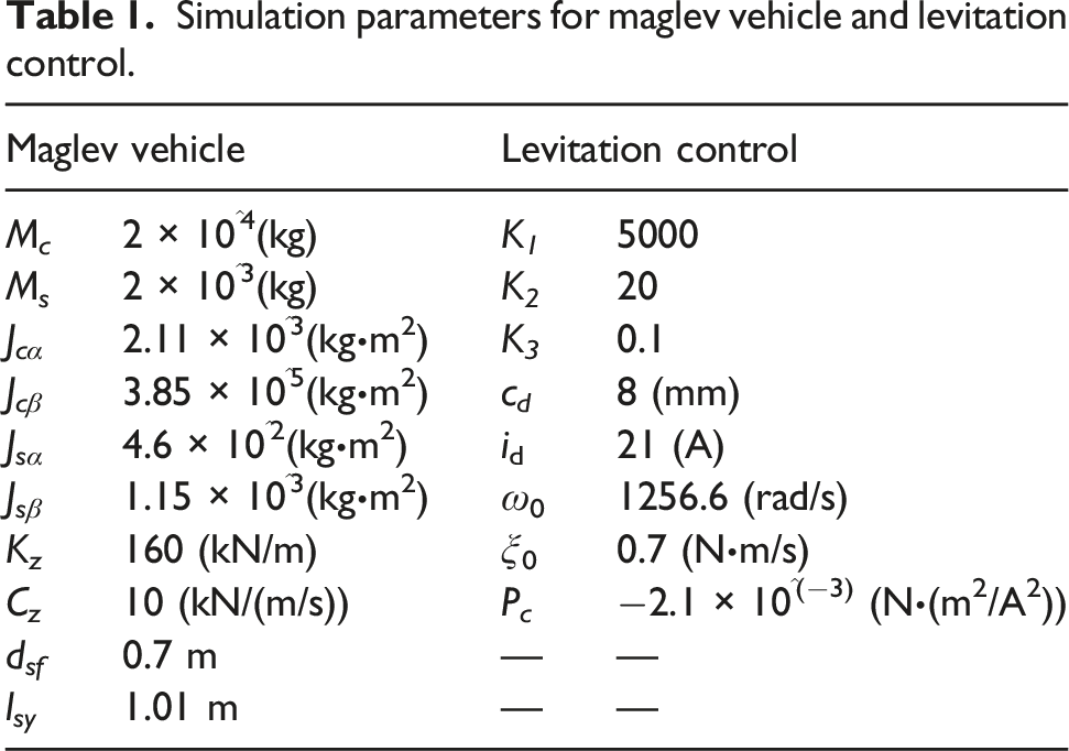
In LMS maglev lines, the subgrade structure is just as important as the bridges, seen in Figure 1. The maglev track must be supported by the unique structural form in the subgrade section to guarantee enough vertical space to perform the maglev train’s holding track running. The at-ground-structure is named for this type of construction, places on the pre-treated subgrade and is evenly elastically supported. However, both the track and the at-ground-structure are deformed induced by the moving maglev train. The superposition of the two deformations has a direct impact on the levitation gap and force, having a negative impact on the train’s smooth running (Feng et al., 2022). A series of discussions on the coupled vibration phenomena in maglev transportation has been conducted in recent years. the actual operation of LMS maglev line.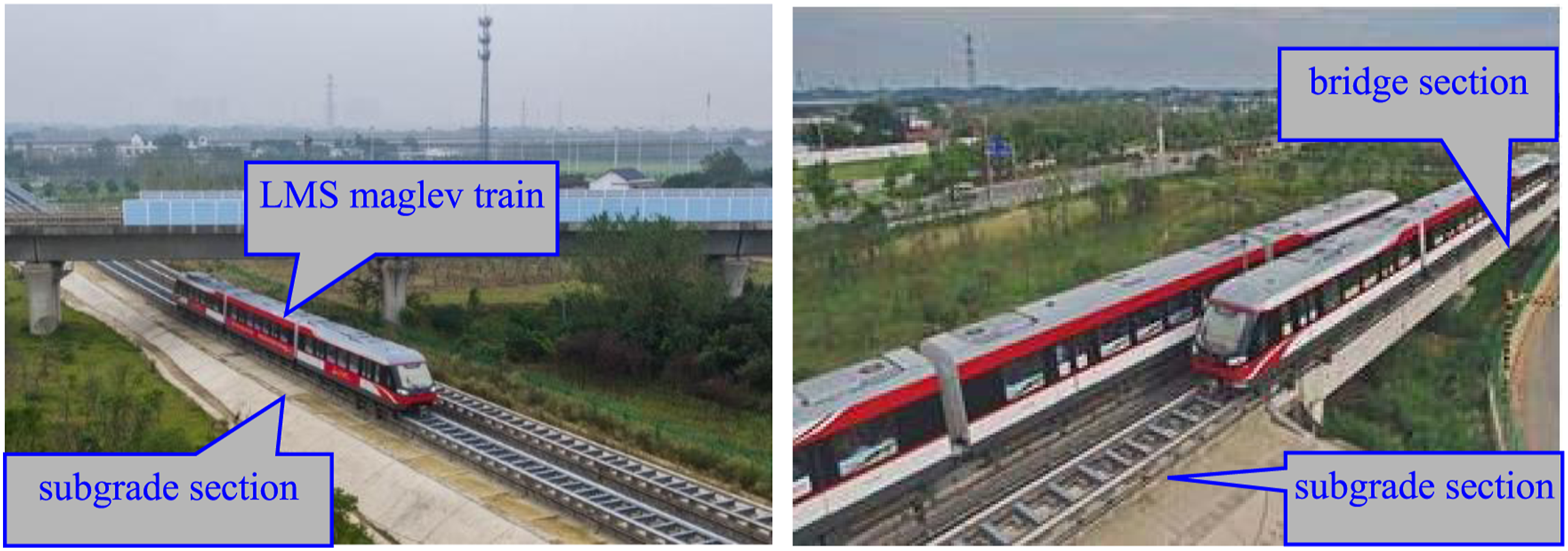
In the experiment research, Liu et al. (2021) presents the mechanisms for the abnormal vibration of newly developed medium-speed maglev test trains based on field tests with various speeds. Li et al. (2021, 2022) tested the dynamic characteristics of the LMS maglev vehicle, track and bridge when the train standing still on the beam. Feng et al. (2023) tested the dynamic responses of the maglev train and simply-supported girder in Changsha Maglev Express with a running speed of 80–140 km/h. the test data showed the maglev train can runs safely and stably. Li et al. (2018) conducted the dynamic filed tests of the simply-supported girder and continuous-girder induced by the LMS maglev train on Changsha commercial maglev line. Han et al. (2016) built the frequency functions for the levitation gap, frame and car body acceleration, and analyzed the influence of bridge mass and damping. Li et al. (2016) measured the environmental vibrations when the high-speed maglev train passing and compared with that induced by the high-speed railway train. They found the peak accelerations were closely related to both maglev train speed and distance off the maglev track.
For numerical model analysis, Chen et al. (2022) established the maglev train-track coupled vibration model considering flexibility track. Xu et al. (2019) provided an effective framework for the dynamic analysis of high-speed maglev trains running on elastic transitional bridges. The result indicated longer transitional bridges will enlarge all the maglev train’s responses. Shi et al. (2022) redesigned the running performance by decoupling the front and rear levitation electromagnets of the levitation bogie. In addition, the seismic responses simulation model of the maglev train-bridge was built, and the results showed the traditional seismic research method would greatly emphasize the seismic performances (Huang et al., 2021), and the effect of uneven settlement on maglev train-bridge coupled system were also analyzed simultaneously (Yau, 2009a). Zhao and Zhai (2002) built the TR06 maglev train model and investigated the vertical vibrations characteristics with random irregular excitation. Kwon et al. (2008) believed the wind load has the major influences for the coupled vibration of maglev train-bridge system during high-speed running. Li et al. (2017) discussed the vibration performance of the at-ground-structure induced by moving maglev train. Wang et al. (2015) verified the reliability of the maglev train-bridge coupled vibration model based on the state feedback control theory by filed test. Xiang et al. (2022) established the 3D theoretical dynamic interaction model of high-speed maglev train-guideway system with active control, and discussed the dynamic performance under the control loop failure state.
The at-ground-structure and maglev track constitute a complicated system due to their complex construction and restrictions. Running maglev train leads to complicated deflections of the system. However, the vibration mechanism of the maglev train-track-at-ground-structure coupled system is still currently unclear and rarely mentioned. So, this paper develops a detailed numerical model for the structural vibration of the LMS maglev train-track-at-ground-structure coupled system. The method’s reliability is proved through experiments. The dynamic response characteristics and mechanism of track-at-ground-structure due to maglev train are then explored. Finally, the high-frequency resonance and resonance suppression mechanism is analyzed.
Dynamic interaction models of the coupled system
Levitation control model of single electromagnetic
As shown in equation (1), the levitation force per levitation electromagnet is determined by the electric current and the air gap.

The PID (proportion-integral-derivative) active levitation control is adopted based on the displacement-speed-acceleration feedback (Shi et al., 2007). It has many advantages, like strong robustness, clear physical definition, intuitive and simple parameter setting, and meets the requirements of levitation control system for stability and effectiveness. However, the fluctuating value of the levitation current must be computed using the equation below:

The velocity feedback variable should be reconstructed because of measured difficultly. The state observer is constructed, as shown in equation (3).


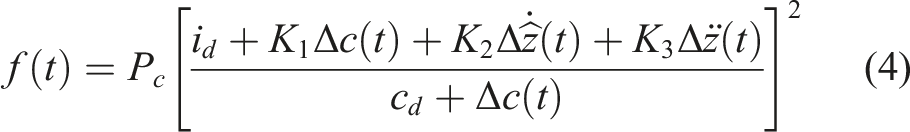
Equation (4) expresses ultimate electromagnetic levitation force for per electromagnetic by combining equations (1), (2) and (3). By adding equations (4) to (40) levitation electromagnets per maglev vehicle, the overall levitation force of the vehicle can be obtained. Actually, the final levitation forces generated by any levitation control strategy should be similar.
Maglev vehicle model
The LMS maglev train is focused as depicted in Figure 2. Each maglev vehicle consists mostly of car body, air springs, levitation frames and levitation electromagnets. 20 vertical air springs links the maglev cay body and levitation frames to generate the secondary suspension, as illustrated in Figure 2(a). A levitation frame is made up of left-hand and right-hand levitation modules joined by a pair of antiroll devices. Every levitation module includes 4 electromagnets. LMS maglev train and the subjected forces: (a) theoretical model; and (b) the forces applying on the maglev car body and levitation frame.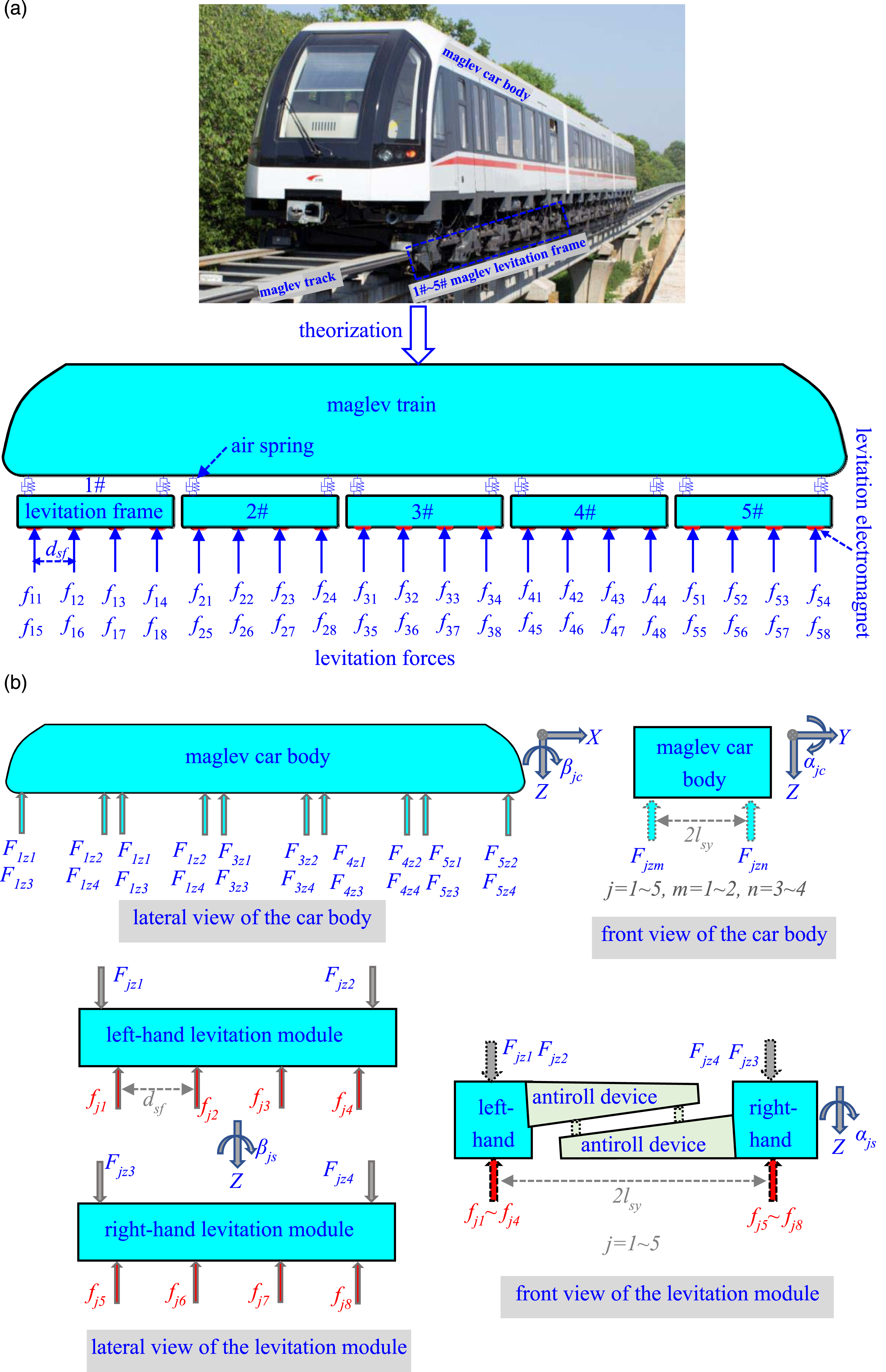
The maglev car body is subjected to spring-damping forces from air springs, as seen in Figure 2(b). The equation of dynamic motion of maglev car body for vertical, rolling, and pitching DOFS are shown as:

The spring-damping forces and the levitation forces commonly influence the levitation modules, shown as Figure 2(b). The equation of dynamic motion of the left-hand levitation modules for vertical and pitching DOFs are written as:
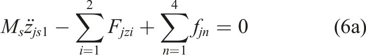
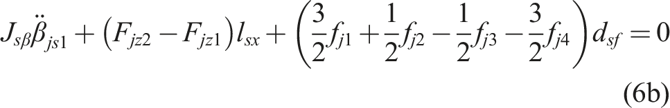
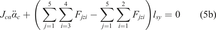
The vertical spring-damping forces and levitation forces act on the whole levitation frame. The dynamic equilibrium equation for the whole rolling (α
js
) DOF is seen as:
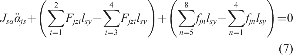
Then, the motion equation of the maglev vehicle after assembled is shown as equation (8).

Finally, per levitation frame has 1 DOF, each levitation module has 2 DOFs and a maglev car body has 3 DOFS. As a result, the whole 28 DOFS for a complete maglev vehicle are examined.
Track-at-ground-structure system model
The prefabricated track at-ground-structure is placed on the pre-treated subgrade and acts closely with the subgrade though its bottom in the vertical direction by its own gravity. Due to the elasticity, the pre-treated subgrade can be simplified as uniformly springs supporting the at-ground-structure in vertical direction, as seen in Figure 3(a). The spring stiffness is directly related to the pre-treated subgrade coefficient. The value of subgrade coefficient is 190 MPa/m according to the Code for design of medium and low speed maglev transit (Ministry of Housing and Urban-Rural Development of the People’s Republic of China, 2017). schematic diagram of track-at-ground-structure system model: (a) simplified model; (b) calculation stiffness model of the discrete support spring; and (c) modal superposition theory of the system model.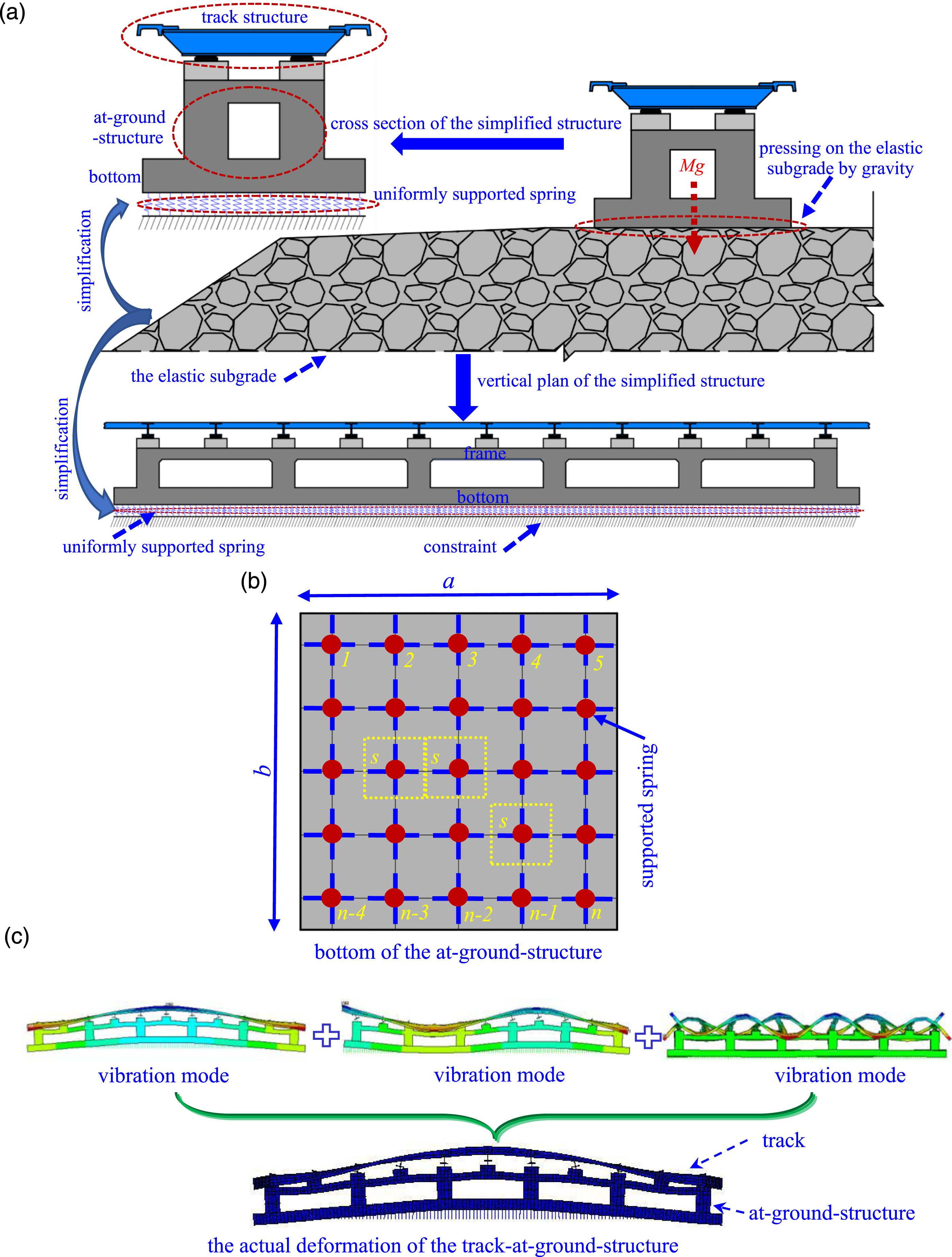
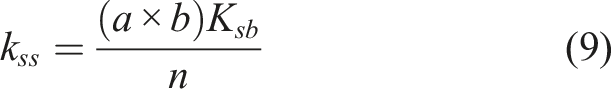
In the simulation model, the at-ground-structure will be discretized into multiple discrete units in the FEA (Finite Element Analysis) software, the uniformly springs connected to each node of at-ground-structure bottom will also be simplified into multiple discrete springs, as seen in Figure 3(b). Hence, the stiffness of each discrete support spring is acquired by equation (9).
The track and at-ground-structure with the supported springs are all deformed suffering the running maglev train because of their flexible characteristic. The maglev track model and at ground model are regarded as whole and solved by modal superposition method (Clough and Penzien, 1993), as seen in Figure 3(c). The equation of dynamic motion of the track-at-ground-structure model gives as:

Due to the modal orthogonality, equation (10) is decoupled as various uncoupled equations of motion:

Every mode is normalized to the structural mass, seen in equation (12)

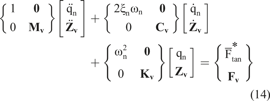
Taking equations (12) to (11), the dynamic differential equation is written as:

Dynamic interaction model
Levitation forces apply on the maglev vehicle upward and the track at-ground-structure downward, coupling the two systems together. Combining equations (8) and (13) and equation (4) serving as the link, a dynamic interaction equation for maglev train-track-at-ground-structure coupled system considering the coupled effect of the levitation control system can be generated as:
The levitation force is influenced with the maglev vehicle and track-at-ground-structure, and affecting the movement of vehicle and track-at-ground structure system as a link. The levitation forces vector applying on maglev train and the generalized external force vector applying on the track-at-ground-structure system are all determined by the levitation force (equation (4)). The incremental-iterative strategy given in the reference (Yau, 2009b) can be adopted to work out the coupled system. The dynamic equation is solved in time domain, and the integral time step length is 0.001s. The total simulation time is determined by the condition that the maglev train has completely left the track-at-ground-structure system. The schematic numerical coupled model for the maglev train-track-at-ground-structure system is presented as Figure 4. The schematic numerical coupled model of the LMS maglev train-track-at-ground-structure system.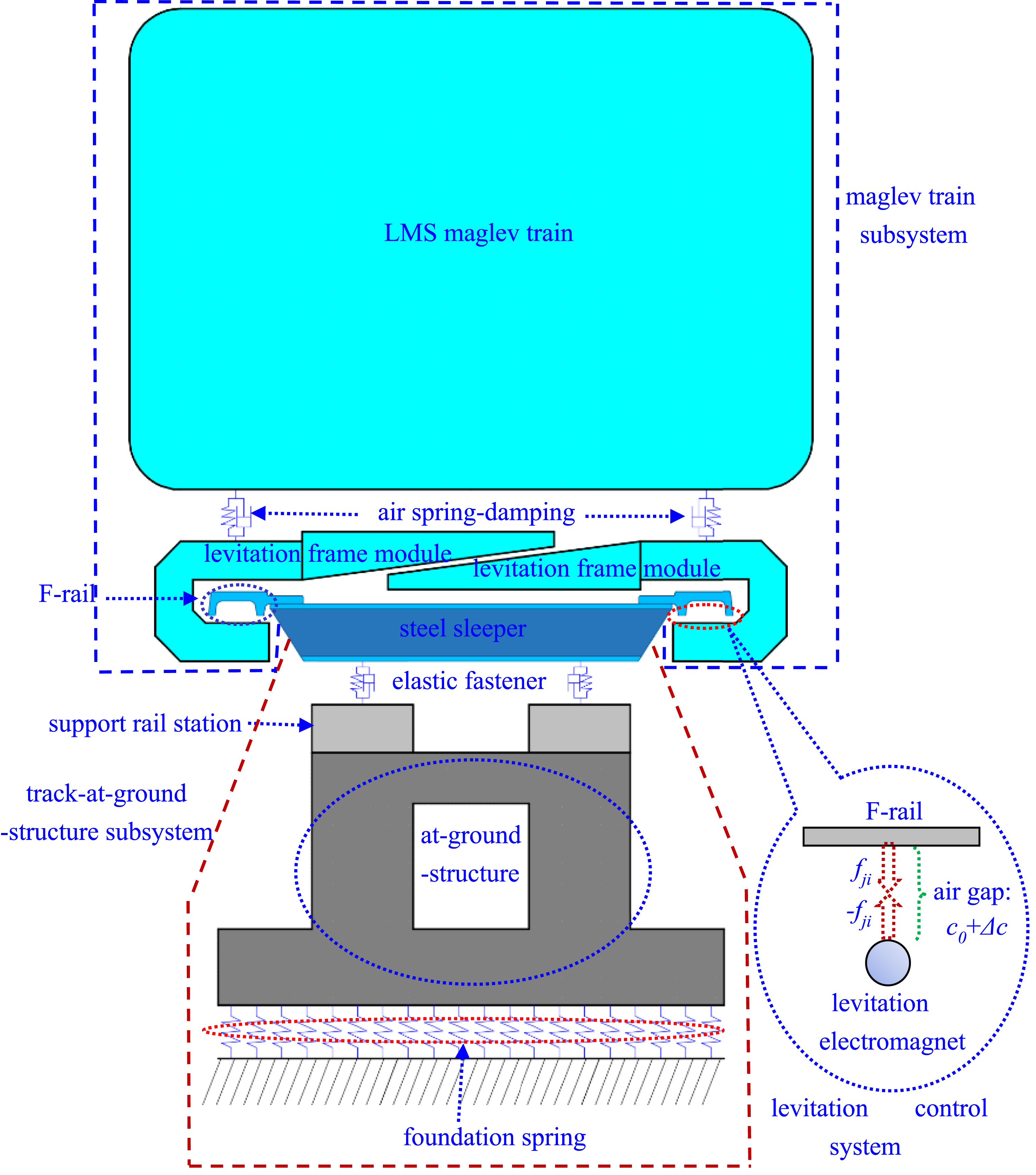
Dynamic characteristics of the LMS maglev train-track-at-ground-structure
Simulation parameters
Maglev train
Simulation parameters for maglev vehicle and levitation control.
Track-at-ground-structure system
Figure 5(a) gives the section for track-at-ground-structure. The track is composed of fasteners, steel sleepers and steel F-rails. The F-rail is continuous supported by fasteners in longitudinal direction with a length of 1.2 m. The F-rail is steel and its Young’ s modulus is 2.1 × 10⁵ MPa, and fastener’s stiffness is 120 kN/m. The strength is 50 MPa for concrete at-ground-structure and support rail bed. The value of subgrade coefficient is 190 MPa/m. Structure size and the finite element model (unit: cm): (a) track-at-ground-structure size; and (b) finite element model of the track-at-ground-structure with supported springs.
The 12m length of subgrade-track transition for per side to reducing the rigidity sudden change from the rigid track to at-ground-structure, and 4 spans at-ground-structures are established with serial numbers of 1#, 2#, 3# and 4#, respectively, illustrated as Figure 5(b). The F-rail and steel sleeper are modelled using shell element, whereas solid elements are adopted on the support rail beds and at-ground-structure. Spring elements are employed to the fasteners and the support discrete springs.
Random track irregularities
Due to the maglev transit starts relatively late, the random irregularities are sparse currently. The track irregularities suggested in previous studies (Shi et al., 2007) are used for following analysis in this study. The random track irregularity can affect the fluctuation value of the levitation gap and can be superimposed into the levitation gap. Hence, it can be set in the simulation model and influence the coupled vibration of the maglev train-track-at-ground-structure system. The function of power spectral density is provided as equation (15).
Model validation
Our team conducted the field test on the 25m simply-supported girder of Changsha Maglev Express, the experiment and bridge sizes description are explained in the previous study (Li et al., 2018). The dynamic interaction numerical model is proposed based on the theory introduced in Section 2. The bridge mode truncation frequency is 200 Hz. That is, the bridge modes within 200 Hz are considered in the simulation. This truncation frequency of 200 Hz is also used in the following analysis of at-ground-structure. The simulation parameters are presented in Table 1.
Figure 6 compares the vertical dynamic responses of the experiment and simulation results for the bridges and maglev car body at 80 km/h. It is obvious that the simulation values are closer to the field test. Therefore, the coupled vibration model of the LMS maglev train-track-bridge system is valid and can properly simulate the vertical dynamic interaction analysis. This further illustrates that the theory presented in this paper is reliable. Vertical dynamic responses comparation of the experiment and simulation model about the 25m simply-supported girder: (a) dynamic deflection of the bridge; and (b) accelerations of the bridge and car body.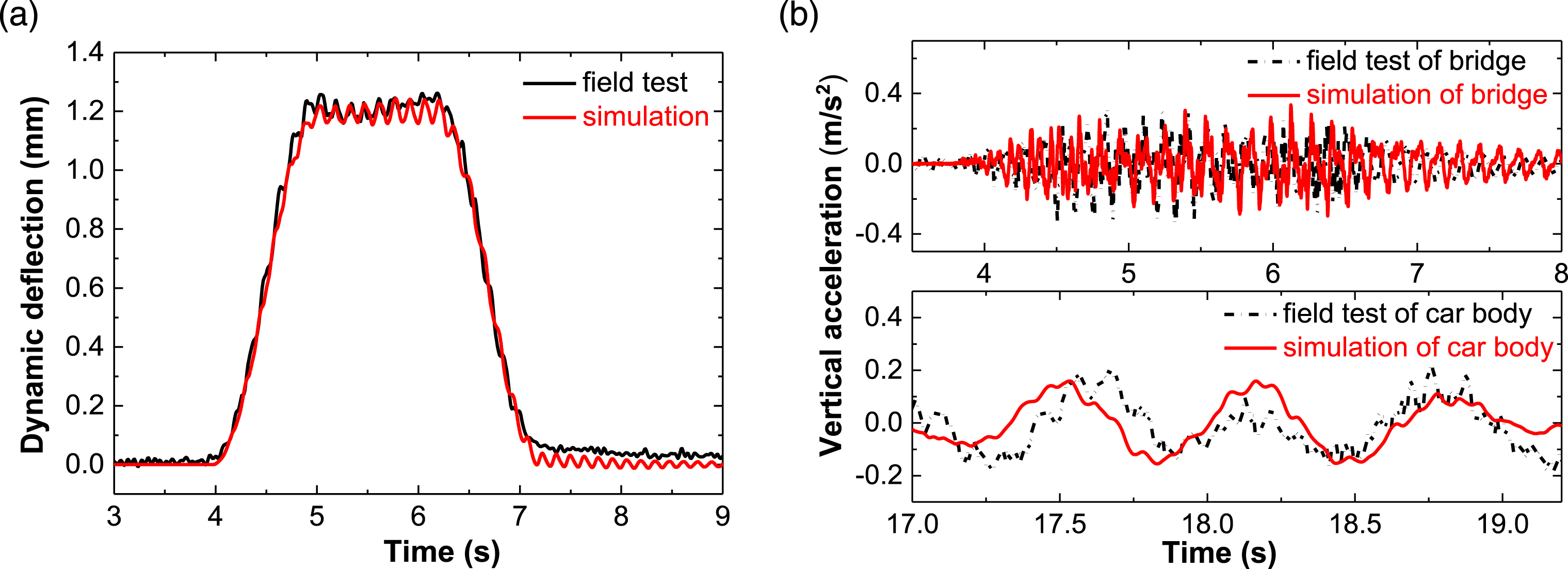
The bridge and at-ground-structure both can be solved by the modal superposition theory. For maglev train-track-bridge structure system model and train-track-at-ground-structure system model, the solution theory is the same, and only the structural types are different. Based on the above validation, it is further indirectly proved that the established coupled vibration model of the LMS maglev train-track-at-ground-structure system is correct.
Modal analysis
Typical modal shapes and natural frequency of the maglev track-at-ground-structure system.
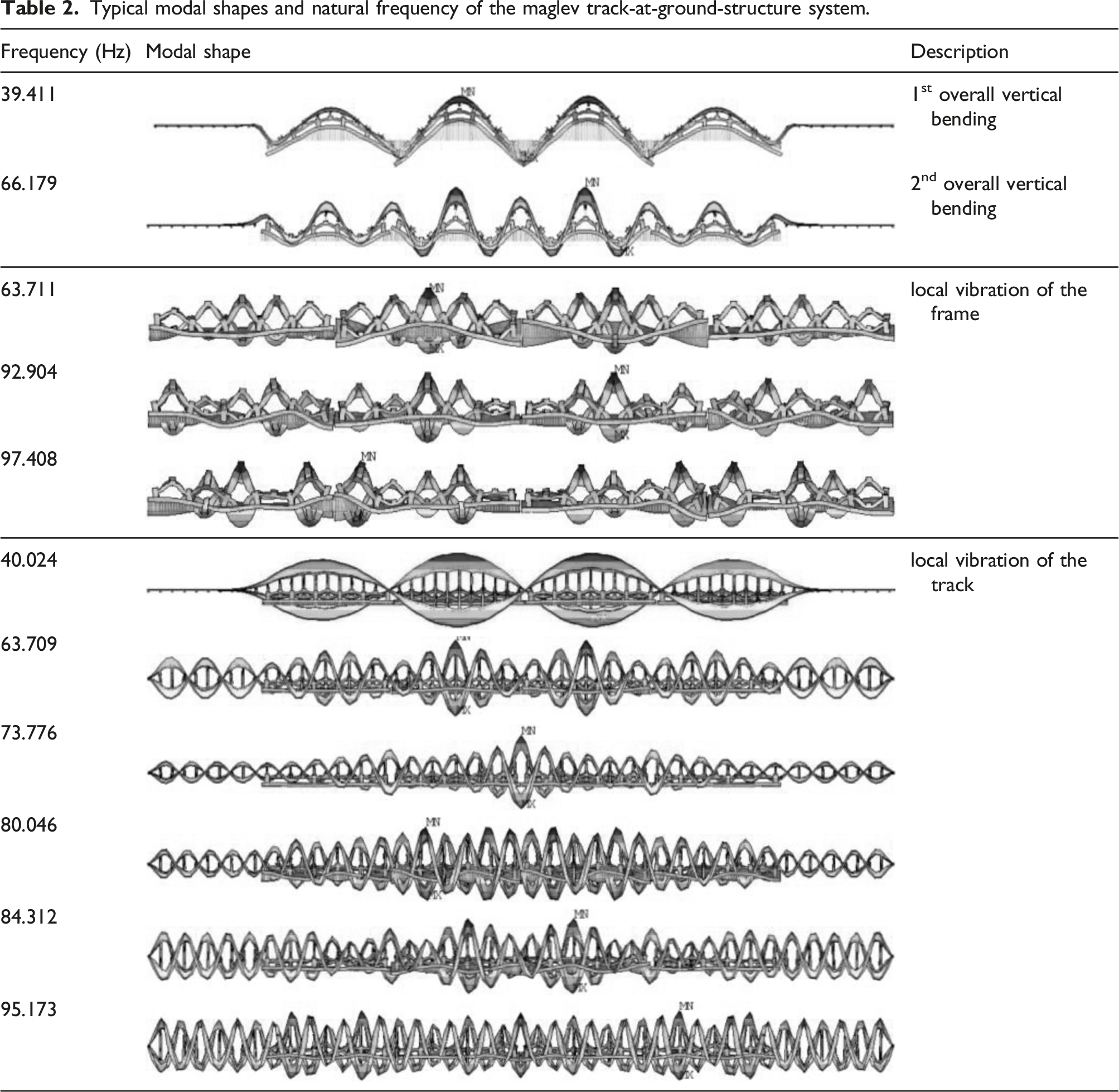
Due to the strong foundation springs support, the first-order overall vertical bending frequency of at-ground-structure is comparatively large with 39.411 Hz. Compared with the traditional bridge structure, the at-ground-structure has the smaller span of 13.1 m and stronger uniform supported by the subgrade at the bottom in vertical direction. The greater the stiffness of the subgrade, the higher vertical bending frequency. Hence, its first-order vertical bending frequency is significantly larger.
The short distance of 2m between adjacent frames causes local vertical vibration frequencies of the frame to be high and with a short vibration wavelength. However, the vibration frequency of the F-rail varies changes from 40 Hz to 100 Hz, and the vibration wavelengths are various. This is mainly due to the low vertical stiffness of the F-rail and its fastener connection.
According to statistics within 100 Hz, there are only 4 overall vibration modes of at-ground-structure, and the local vibration modes of the frame are sparse with a relatively high frequency between 60 Hz to 100 Hz, while the local vibration modes of the F-rail are dense between 40 Hz to 100 Hz. This is the vibration modal distribution of each part for the at-ground-structure.
Dynamic responses
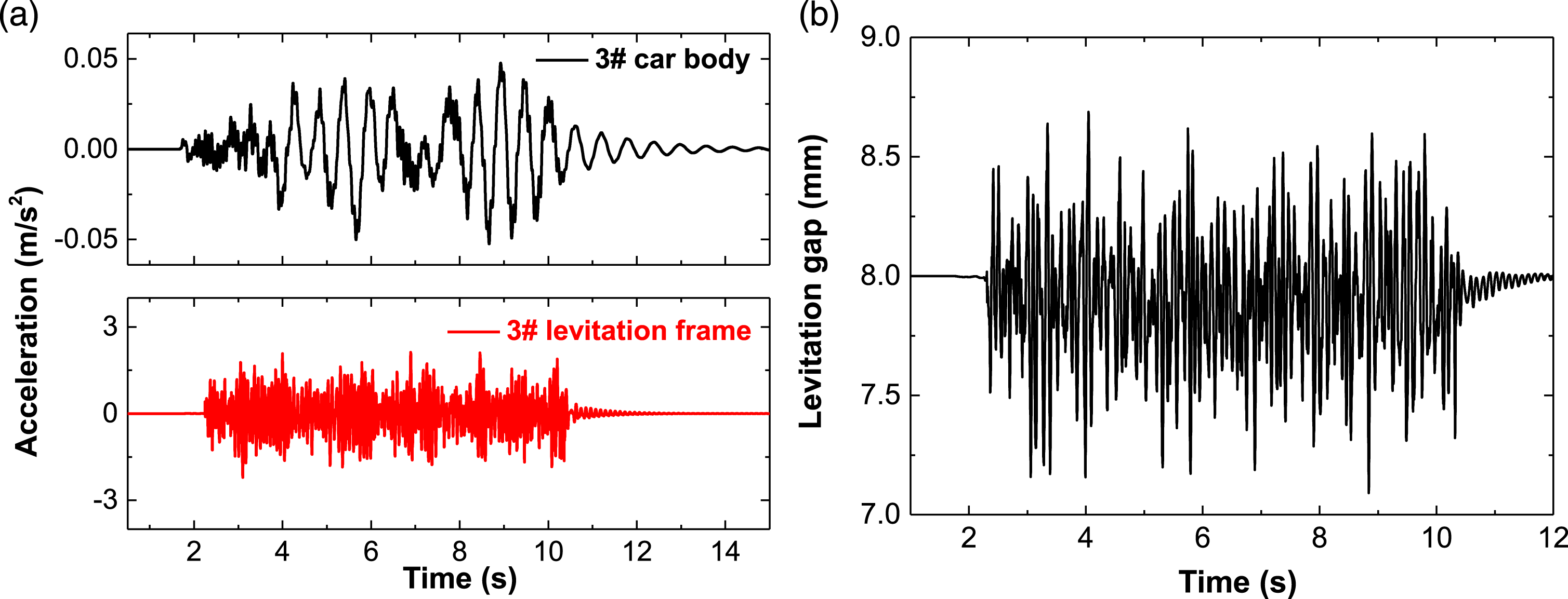
Figure 7 (a) and 7(b) presents the comparison of the dynamic deflections and accelerations of the bottom, frame of at-ground-structure and F-rail at the speed of 80 km/h. For both the dynamic deflection and acceleration of these components, the descending order of the dynamic responses is the F-rail, the frame and the bottom. Figure 8(a) shows the accelerations of the car body and levitation frame. The accelerations of the levitation frame are obviously larger and more violent than that of the car body. The levitation gap is seen in Figure 8(b), and the maximum fluctuation values is 1.596 mm, meeting the fluctuation limit value of ± 4 mm for the levitation gap required in “Technical specification of system for the levitation control of medium-low speed maglev transportation vehicle” (Ministry of Housing and Urban-Rural Development of the People's Republic of China, 2014). The maglev train runs smoothly with a small acceleration of 0.051 m/s2, which is obviously less than the limit value of 1 m/s2 for the acceleration of the maglev train required in “Standard for design of high-speed maglev transit” (Ministry of Housing and Urban-Rural Development of the People’s Republic of China, 2021). Vertical dynamic responses of the track-at-ground-structure system: (a) dynamic deflections; and (b) accelerations. Vertical dynamic responses of the maglev vehicle: (a) accelerations of the car body and levitation frame; and (b) levitation gap.
As analyzed above, overall vibration, the obviously local vibrations of the F-rail and the frame structure occur in the track-at-ground-structure system. The total deflection of F-rail consists of system’s overall deflection, the local deflections of F-rail and frame structure. The total deflection of frame structure also includes the overall deflection of at-ground-structure and local deflection of the frame. Hence, the total deflection of F-rail is obviously larger than that of frame structure, and that of the frame structure is bigger than that of the bottom. The local deflection of F-rail is the largest because its intensive local vibration modal.
The total deflection of the F-rail will disturb the levitation control system, and cause fluctuations of the levitation gap. However, the fluctuations value of the levitation gap is relatively small, and this explains the levitation control system adopted in this paper has a good levitation control capacity. The levitation force acts on the levitation frame directly, and transmits to the car body through the secondary suspension system (air springs) with a good vibration isolation performance, generating minor vibration of the car body.
Performing spectrum analysis on Figure 7(b), the acceleration frequency spectrum of the bottom, the frame of at-ground-structure and the F-rail are displayed as Figure 9(a). Because the local vibrations are occurred both in the F-rail and frame, and the vibration frequency is higher, obviously peaks in the range of 50–100 Hz both for frequency spectrum of the F-rail and frame accelerations appear. The vibration of frame within 50 Hz is obviously smaller than that between 50 Hz and 100 Hz due to the overall vibration within 50 Hz. For F-rail, large vibration peaks occur not only in the high frequency band(50–100 Hz), but also in the low frequency band (within 50 Hz), and these acceleration amplitudes are significantly greater than that of the bottom and frame. This is mainly due to supporting the levitation force directly and small mass of the F-rail compared to the at-ground-structure. Spectral analysis of Figure 7(b): (a) bottom and frame of track-at-ground-structure; and (b) comparison of the bottom and frame after 50 Hz low pass filter.
Due to different dominant frequency bands, only the overall vibration is left over after 50 Hz low pass filter in time domain. The overall vibration of the at-ground-structure is mainly concentrated within 50 Hz, while the local vibration frequencies of the frame are larger than 50 Hz. Hence, 50 Hz low pass filtering is adopted. Unlike shown in Figure 7(b), the acceleration difference between bottom and frame is not significant and basically equal, as seen in Figure 9(b). Thus, the vibrations of at-ground-structure induced by the running maglev train belongs to relatively low frequency vibration within 50 Hz for the bottom and higher frequency vibration between 50 Hz to 100 Hz for the frame structure.
Resonance analysis
Resonance mechanism
The LMS maglev train structure is special and like moving uniform loads acting on the at-ground-structure. A maglev train contains 3 maglev vehicles, and the space between adjacent levitation force and electromagnets of adjacent suspension frames are both 0.7 m (l
s
= 0.7 m, l
a
= 0.7 m). While, the distance between adjacent electromagnets of adjacent maglev trains (l
ad
) is more than 0.7 m. Hence, the dynamic effect can be regarded as 3 sections moving loads and each section include 20 pairs electromagnetic force with an equal distance of 0.7 m acting on at-ground-structures, as seen in Figure 10. Schematic diagram of the equidistant and uniformly distributed loads when the maglev train moves on the at-ground-structure.
Figure 11(a) presents the acceleration of at-ground-structure bottom center in time domain when the maglev train moves with different speeds (v = 70 km/h, 100 km/h and120 km/h, respectively). The maximum accelerations are 0.335 m/s2 (v = 70 km/h), 1.069 m/s2 (v = 100 km/h) and 0.688 m/s2 (v = 120 km/h), respectively. The acceleration at 100 km/h is significantly greater than that at 70 km/h and 120 km/h. The acceleration waveform presents a regular sinusoidal waveform. The time interval of the 10 adjacent sine wave peaks is 0.253s and the corresponding waveform frequency is 39.526 Hz. But the regular sinusoidal waveform phenomenon does not exist at other speeds. The accelerations of at-ground-structure bottom center versus train speed: (a) time series; and (b) frequency spectrum.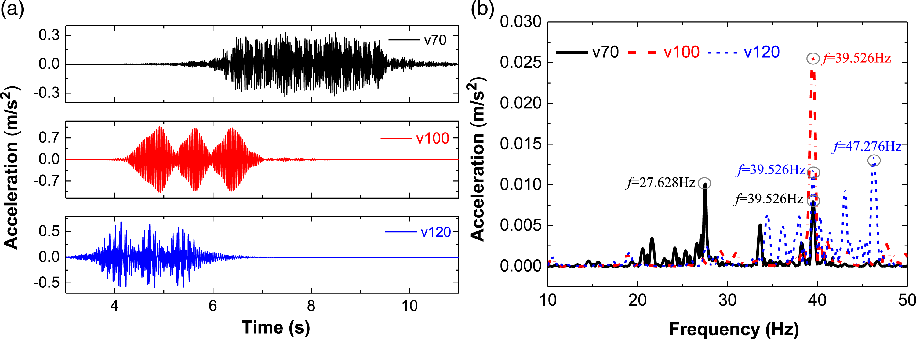
Figure 11(b) shows the frequency domain within 50 Hz converted by the time domain waveform in Figure 11(a). The acceleration of at-ground-structure bottom has obvious peaks at 27.628 Hz and 39.526 Hz with the speed of 70 km/h, while peaks in frequency domain occur in 39.526 Hz and 47.276 Hz when the speed is 120 km/h. However, the peak only appears at 39.526 Hz while the speed is 100 km/h, and this peak value (f = 39.526 Hz) is obviously larger than the whole peaks that appear in the frequency domain with the other two speeds (v = 70 km/h and v = 100 km/h).
20 cyclic levitation forces with equal longitudinal distance of 0.7 m act on the at-ground-structures when each maglev vehicle passing, hence, the excitation frequency of the adjacent electromagnetic levitation force on the at-ground-structures can be calculated as:
As the train speed is 70 km/h, 100 km/h, and 120 km/h, respectively, the excitation frequencies of adjacent electromagnetic levitation forces are 27.778 Hz, 39.683 Hz, 476.619 Hz correspondingly. These three frequencies are very close to the peak frequencies of the spectrum curves under three train speeds in Figure 11(b) (V70: 27.628 Hz and 39.526 Hz; V100: 39.526 Hz; V120: 39.526 Hz and 47.276 Hz). Due to the repeated loading of adjacent levitation forces, at-ground-structure has obvious acceleration frequency peaks at the loading frequency of corresponding running speeds. Meanwhile, the first-order vertical bending frequency of at-ground-structure is 39.411 Hz. Therefore, besides the peaks at the adjacent levitation force loading frequencies under three speeds, the acceleration peaks also appeared near the first-order vertical bending frequency.
Further comparison confirms that the first-order vertical bending frequency of the at-ground-structure (39.411 Hz) is very close to the adjacent levitation force loading frequency (39.526 Hz) when the train speed is 100 km/h, while quite different to that of other train speeds. The nature frequency (39.411 Hz) and repeated loading frequency (39.526 Hz) with the speed of 100 km/h are very close, resulting in the resonance phenomenon of the at-ground-structure induced by the moving maglev train, and an obvious resonance waveform appears. Hence, the vibration acceleration is significantly amplified in the resonance frequency and obviously larger than that at this frequency point (39.526 Hz) in other two speeds.
This resonance phenomenon endangers the safe service of the at-ground-structure. It is strongly supported by the foundation in the vertical direction, leading to its large vertical rigidity. Meanwhile, the longitudinal distance between the adjacent electromagnets of the LMS maglev train is small, and the repeated loading frequency is high. Therefore, the vertical resonance of the at-ground-structure caused by the running LMS maglev train is a high-frequency resonance phenomenon due to the larger natural frequencies of the at-ground-structure.
Resonance suppression
Due to the high-frequency resonance phenomenon based on the above analysis, Figure 12 shows the vertical accelerations of the at-ground-structures with different first-order vertical bending frequencies when the maglev train runs at the speed of 100 km/h. The different first-order vertical bending frequencies of the at-ground-structure are adjusted by changing the overall mass of the at-ground-structure (changing the value of the concrete density). When the first-order vertical bending frequency is 20.567 Hz and 61.325 Hz, the resonance phenomenon of the at-ground-structure caused by the 20 repeated loading of adjacent electromagnetic forces disappears, and the peak value at the corresponding vertical bending frequency is significantly reduced. The accelerations of at-ground-structure bottom center at the speed of 100 km/h versus first-order vertical bending frequencies: (a) frequency domain; and (b) time domain.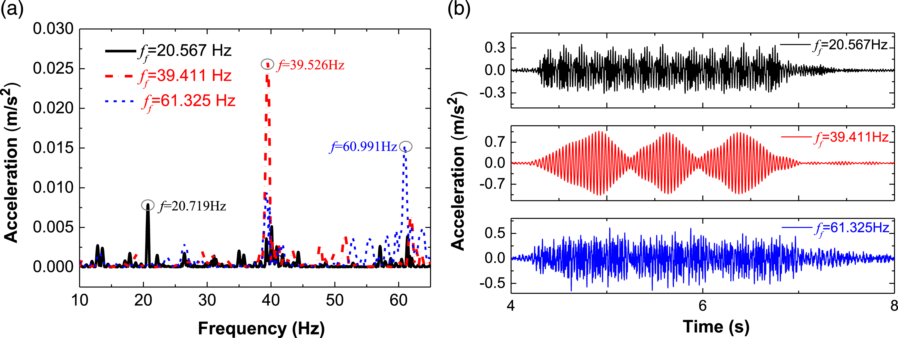
Meanwhile, when changing the distance between adjacent electromagnetic levitation forces of adjacent levitation frames (L
a
≠0.7 m), the phenomenon of repeated equal-spaced loading of 20 electromagnetic forces disappears. Figure 13 presents the acceleration of the at-ground-structure bottom center at different vehicle speeds when La is 1m. The sine wave with the speed of 100 km/h is gone and the resonance phenomenon of the at-ground-structure due to repeated equal-spaced loading disappears when L
a
is equal to 1m (L
a
≠L
s
). The accelerations of at-ground-structure bottom center in time domain when La is equal to1m.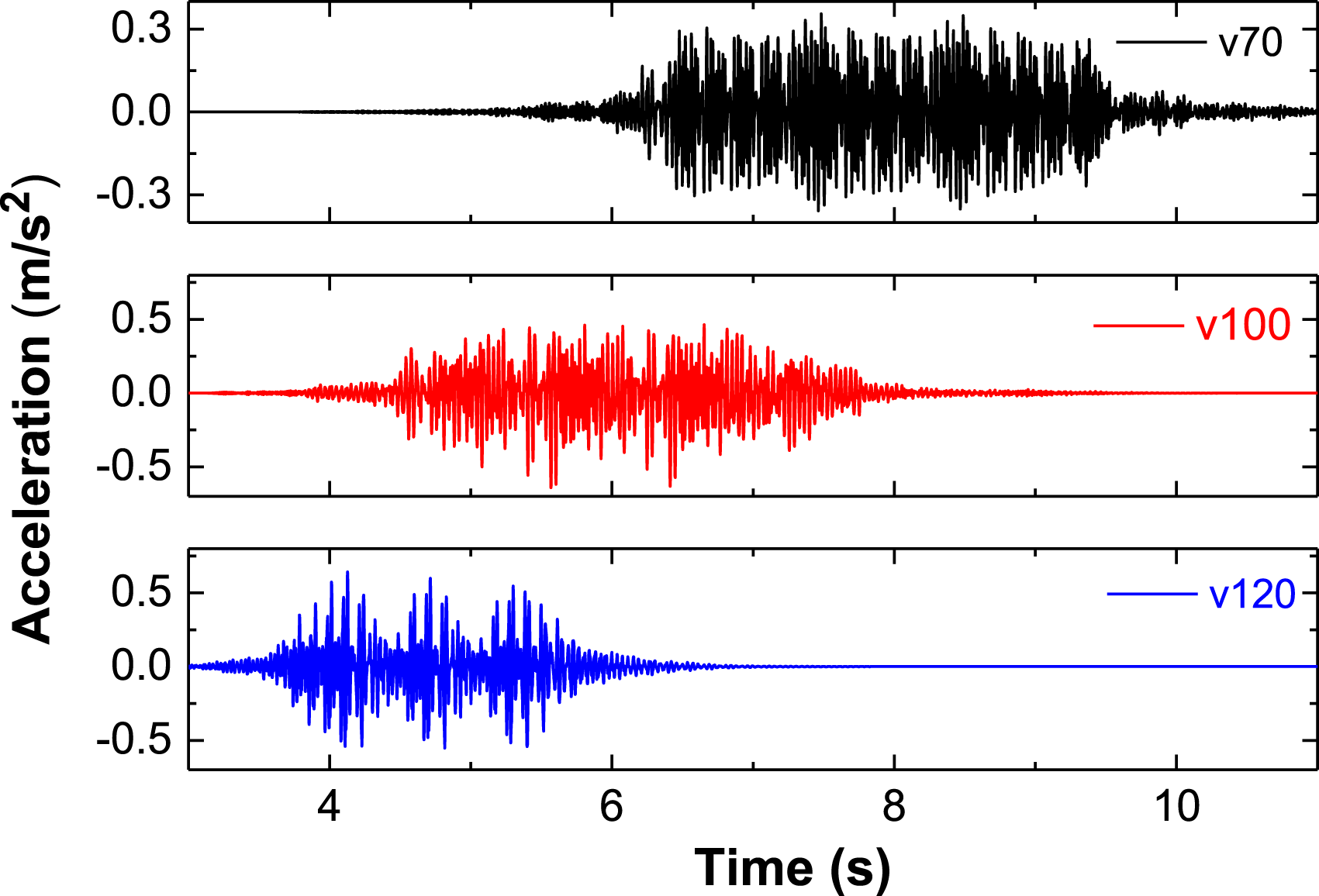
Therefore, the levitation forces loading frequency avoids first-order vertical bending frequency of at-ground-structure, or the levitation forces are eliminated multiple times loading at equal intervals, the high-frequency resonance phenomenon of the at-ground-structure caused by the moving maglev train can be effectively avoided. Thereby, the dynamic performance of the at-ground-structure is improved, and the stable operation of the maglev train is guaranteed.
Conclusions
The major conclusions can be drawn from this paper as follows: 1. The vertical overall rigidity of at-ground-structure is rather high. It’s easy to see the dense local frame vibration modes and F rail vibration modes. The local vibration of the F rail and the frame is short-wave compared to the overall vibration of the at-ground-structure. 2. The F rail and the frame of the at-ground-structure have a relatively high local vibration frequency. The F rail has the greatest dynamic deflection and acceleration, followed by the frame, and finally the bottom. The overall low-frequency vibration of the at-ground-structure and local high-frequency vibration of the frame are included in frame vibration. 3. The high-frequency resonance phenomena of the at-ground-structure occurs when the loading frequency of the neighboring levitation force is close to the first-order vertical bending frequency of the at-ground-structure. The loading frequency avoids its first-order vertical bending frequency, or the levitation forces are eliminated multiple times loading at equal intervals, the high-frequency resonance of at-ground-structure disappears.
Footnotes
Declaration of conflicting interests
The author(s) declared no potential conflicts of interest with respect to the research, authorship, and/or publication of this article.
Funding
The author(s) disclosed receipt of the following financial support for the research, authorship, and/or publication of this article: this work was funded by the National Natural Science Foundation of China (Grant No. 52108417), Natural Science Basic Research Program of Shaanxi (Grant No. 2021JQ-101).