
Abstract
In practice, reinforced concrete (RC) infilled frames having longer span are provided with tie columns to improve structural integrity but previous work ignored tie columns in studying the effect of masonry infills on progressive collapse resistance of RC frames. Therefore, aim of this study is to explore the effect of tie columns on the progressive collapse resistance of RC infilled frames under column removal scenarios. The high-fidelity-based finite element model of RC infilled frames were first developed and validated with published experimental results. The validated model was then further evolved to an RC infilled frame having tie columns to evaluate the influence of tie columns on the load transfer mechanism and the resistance of the RC infilled frame against progressive collapse. Thereafter, the numerical model was further utilized to study the effects of the pertinent parameters, including the number of stories, the span length of the frame and the longitudinal reinforcement ratio of the tie columns. Finally, equivalent strut model was suggested for macro-modeling of RC infilled frames having tie columns in engineering practice. The results showed that incorporating tie columns makes truss mechanism more fully mobilized in masonry infill walls and the inclined angles of primary struts in each sub-panel of the infill wall are increased, improving the vertical components of diagonal compression in resisting the gravity load. Consequently, introducing tie columns at middle span of infill wall panels helped to increase the initial stiffness (about 19%), peak resistance (about 26%) and post-peak resistance of RC infilled frame under a middle column removal scenario. Such beneficial effect of tie columns becomes more significant for infilled frames with larger spans, and the longitudinal reinforcement ratio of tie columns should be ≤ 0.24%.
Keywords
Introduction
Progressive collapse of buildings is a very catastrophic accident, which is triggered by the local failure of structural members (i.e., walls or columns), leading to a disproportionately partial or complete collapse of a structure. These structural damages are caused by accidental loading including fire, vehicle impact or explosion etc. Progressive collapse typically results in severe losses in human lives and properties, such as incident of Plasco Building in 2017 (Iran) and World Trade Center in 2001 (New York).
Numerous experimental and numerical studies have been conducted over the last two decades to understand the progressive collapse behavior of reinforced concrete (RC) building structures at different levels, including beam-column sub-assemblages (Qian et al., 2018, 2022; Valipour et al., 2016; Yang et al., 2021; Yu and Tan, 2013a, 2013b), beam-slab sub-assemblages (Lu et al., 2017; Qian et al., 2016; Ren et al., 2016; Yu et al., 2018; Yu, Luo, et al., 2020; Yu, Tang, et al., 2020), planar frames (Li et al., 2021; Lim et al., 2017; Yu and Tan, 2017; Zhou et al., 2019) and overall structures (Brunesi et al., 2015; Feng et al., 2022; Petrone et al., 2020; Praxedes and Yuan, 2021; Shan et al., 2019) etc. In previous researches (Baghi et al., 2018; Brodsky and Yankelevsky, 2017; Li et al., 2016; Qian and Li, 2017; Shan et al., 2016), masonry infill walls have been proven to have a substantial impact on the resistance of RC frames to progressive collapse.
The experimental work performed by Shan et al. (2016) and Li et al. (2016), in which two 1/3 scaled two-story RC frames having four bays were tested under middle column removal scenario (CRS). The results showed that infill walls improved the peak resistance as well as the initial stiffness of the RC frame, but they decreased the ductility and changed the load distribution pattern (Li et al., 2016; Shan et al., 2016). Similarly, Qian and Li (2017) explored the structural behavior of infilled RC frames (IFF) having three story and two bays with full height walls (FHIW) under a penultimate CRS. It was reported that ignoring the effect of infill walls could lead to significant inaccuracy in determining the stiffness, strength and failure modes of infilled frames against progressive collapse. Buitrago et al. (2021) studied a two-story infilled RC frame under CRS and discovered that due to infill walls the axial load on the neighboring column increases by about 60% in comparison to a bare frame.
Besides experimental works, numerical studies have been recently adopted to explore the progressive collapse performance of RC infilled frame structures. For numerical modeling mainly two types of techniques are used: i.e., micro- and macro-modeling. The micro-modeling is also termed as high-fidelity modeling because masonry units are modeled with solid elements and the mortar between the units is represented either through cohesive element or contact algorithm (Di Trapani et al., 2020; Li et al., 2016; Yu et al., 2019, 2021). The results of micro-modeling are able to demonstrate failure modes, load transfer paths and resistance curves of infilled frames against progressive collapse. In particular, most tests are conducted with single-story of infill walls under limited scenarios, but the micro-modeling can help to show the load transfer paths of multi-story infilled frames under various CRSs (Yu et al., 2019) and link the dynamic response and static behavior of the infilled frames (Yu et al., 2021). Moreover, the load transfer paths are the key foundation to propose macro-models of infill walls, which are equivalently represented by strut models (Di Trapani et al., 2020, 2021; Li et al., 2019; Shan et al., 2016; Yu et al., 2019, 2021). For FHIWs, the inter-story load transfer paths are mobilized with increasing vertical deformation, improving the structural capacity larger than by just simply adding the enhancement of every single-story infill wall. For conservatism, such inter-story effect is ignored in the macro-models, but for accuracy, it should be considered and thus a more sophisticated macro-model is proposed (Di Trapani et al., 2021). As macro-modeling is much more computationally-efficient, it is preferred for overall structural analysis (Eren et al., 2019; Feng et al., 2022).
Recently, the investigation on the contribution of infill walls to structural resistance against progressive collapse has been extended to post-tensioned RC frames (Shan and Li, 2022) and steel frames (Qian et al., 2023). The results indicated that the infill walls significantly improve progressive collapse resistance of the frames at small deformation.
Among those researches, during the tests of Li et al.(2016) and Buitrago et al. (2021), the ratio of net span to height (RSH) of a single infill wall panel was 1500/950 = 1.58 and 4700/2800 = 1.68, respectively. However, in the tests of Qian and Li (2017), the RSH of a single infill wall panel was 1650/685 = 2.41 and 2250/685 = 3.28. The RSH of infill panels used in the above studies varies in a wide range and some exceed the limit in practice. If the net span or the length of the infill wall panel is too long, a tie column should be incorporated to improve the out-of-plane stability of the large wall panel under seismic loads. Okail et al. (2016) found that confining components are crucial to keep the strength and ductility of confined walls under lateral loads. Tabrizi and Soltani (2017) conducted experiments on the seismic behavior of both confined and unconfined masonry walls and found that the ductility and strength of masonry walls are greatly increased by incorporating intermediate tie-columns. Tie columns are primarily utilized to maintain the integrity of masonry following diagonal cracking and to provide post cracking deformation capacity (Bourzam et al., 2008). As per Chinese practice and code (GB 5001-2010, 2016), tie columns should be introduced in a wall if the wall is longer than 5 m or the height of the two story, and moreover, the tie columns should be given with a spacing of 3.0 m–3.5 m if the length of the wall exceeds 5 m.
In summary, previous research works mainly focused on the effects of infill walls on the structural resistance of typical RC frames against progressive collapse. Now the research interests have been extended to the infilled post-tensioned frames and steel frames. However, the contribution of tie columns to progressive collapse resistance is ignored. In practice, it is required to incorporate tie columns in infill walls having high RSH or wall length exceeding 5 m. After incorporating tie columns, the load transfer mechanisms and the interaction of the infill wall with the frame will be different in resisting progressive collapse. Therefore, it is imperative to study the effect of tie columns on the progressive collapse resistance of RC infilled frame having high RSH.
To this end, the structural behavior of long span RC infilled frame having tie columns (IFFT) under CRS is investigated using high-fidelity-based numerical modeling approach. This study enables a direct comparison with the results obtained from the case having no tie-column as reported by Qian and Li (2017). Moreover, parametric studies are conducted to explore the effects of span length, number of stories and longitudinal reinforcement ratio of tie columns on structure behavior of RC IFFT. Finally, an appropriate macro-model is proposed for the analysis of infilled frame having tie columns.
The body of the paper is organized as follows: The numerical model and its validation is provided in the next Section, the modeling and analysis of RC infilled frame having tie columns is introduced afterwards. Then the parametric studies of RC infilled frames with tie columns against progressive collapse are provided. Moreover, to facilitate overall structural analysis, another Section introduces a macro-modeling technique for the infilled frames. In the second last Section, a case study illustrates how the proposed model is used and the final Section provides the main conclusions.
Numerical modeling of RC infilled frames
Brief introduction of the referenced experiment
Qian and Li (2017) conducted experiment on quarter scaled RC frames using FHIW under a penultimate CRS, including non-seismically designed infilled frame (WNL) with a long span of 2400 mm, seismically designed (WSS) and non-seismically designed infilled frame (WNS) with a short span of 1800 mm. The other geometric properties of the three specimens were identical. Each specimen contained two bays and three stories in which the penultimate column was removed at the ground story. The same type of masonry was used in the second and third story. The geometric dimensions and the reinforcement detailing for WNL are illustrated in Figure 1. The dimension of beams was 90 mm × 140 mm × 2250 mm. The dimension of columns used for the first story was 150 mm × 150 mm × 900 mm and for the second and third story 150 mm × 150 mm × 825 mm. Infill walls were constructed with concrete masonry units (CMUs) and tie bars were used for connecting the infill walls to the framed columns. At the top of the remaining penultimate column a point load was applied in the vertical downward direction with displacement control. Further details about the model can be referred to the paper (Qian and Li, 2017). Geometry and structure detailing of the reference specimen WNL (unit: mm) (Qian and Li, 2017).
Finite element modeling
The referred three specimens are modeled in commercial software LS-DYNA. The finite element (FE) model is shown in Figure 2. At the ground story, fixed support condition is considered at the bottom of the columns. Similarly, a rigid plate is utilized to create a quasi-static loading condition with displacement-control on top of the middle column, which is defined by a velocity-time curve (Yu et al., 2019). To simulate displacement-control loading, the velocity at first rises with time and then remains constant. Additionally, the CMU infill walls have a significant self-weight, and it is applied prior to the vertical loading and maintained throughout. Finite element model of infilled frame specimens.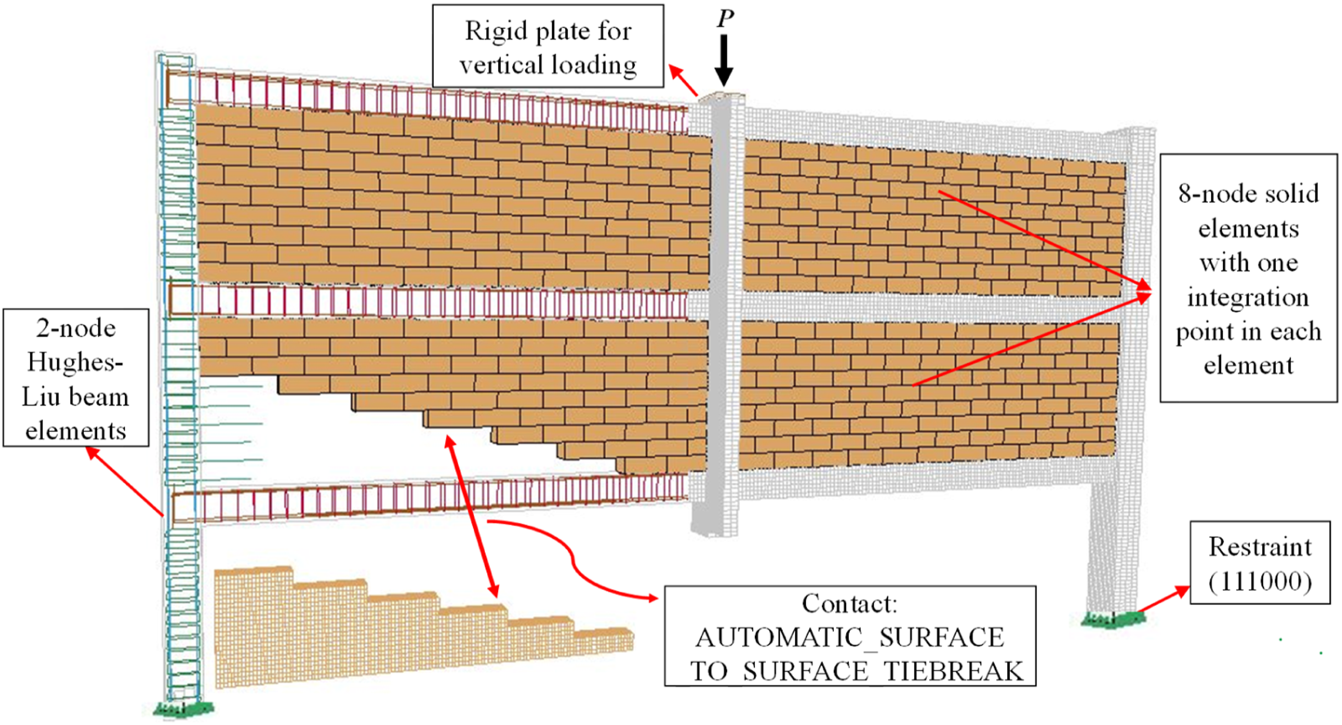
Material properties of infilled frame specimens.
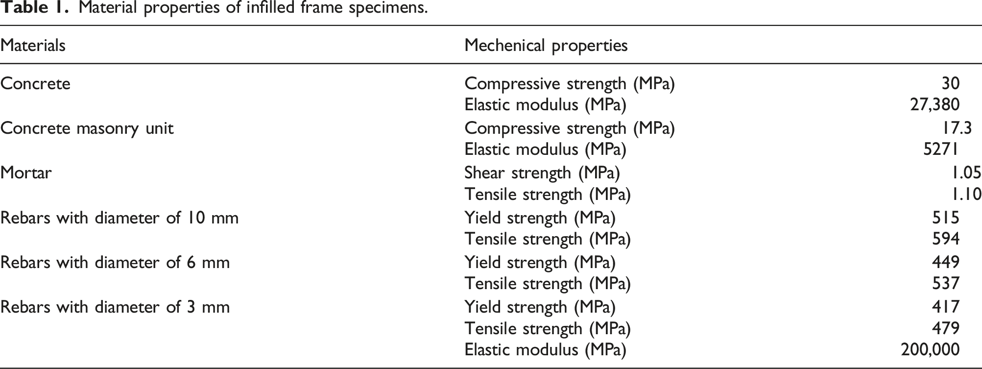
Longitudinal bars and stirrups are modeled using Hughes-Liu beam elements, and a symmetric bilinear elastoplastic model is employed for defining steel properties using the keyword *Mat_Plastic_Kinematic. The size of the elements for rebars varies from 10 to 50 mm. The keyword *CONSTRAINED_LAGRANGE_IN_SOLID (CLIS) in LS-DYNA is used for the perfect bond between the rebars and concrete. Moreover, it is assumed that the lateral bars extended from RC columns to the mortars between CMUs are in perfect bond with mortars as well using the keyword of CLIS. Table 1 lists the mechanical parameters of materials, in which the strengths of different materials are directly taken from the reference (Qian and Li, 2017). It is assumed that elastic modulus of steel reinforcing bars is 200 GPa. The elastic modulus for concrete was Ec = 27.38 GPa (
Validation of numerical models
Figure 3 shows experimental and numerical resistance of the three infilled frame specimens under a middle CRS. The resistance versus displacement curves generally follows a similar pattern for experimental and numerical data. In practice, the randomness of mortar joint quality and workmanship made FE models difficult to reflect abrupt drop in resistance produced by wall cracking. However, the numerical and experimental peak resistance of all the specimens is in good agreement. For instance, the ratio of numerical to experimental peak capacity of WNL, WNS and WSS is 0.996, 1.008 and 0.998 respectively, and the ratio of numerical and experimental residual capacity of the three specimens is 1.03, 0.967 and 1.08 respectively. Experimental and numerical progressive collapse resistance of RC infilled frames.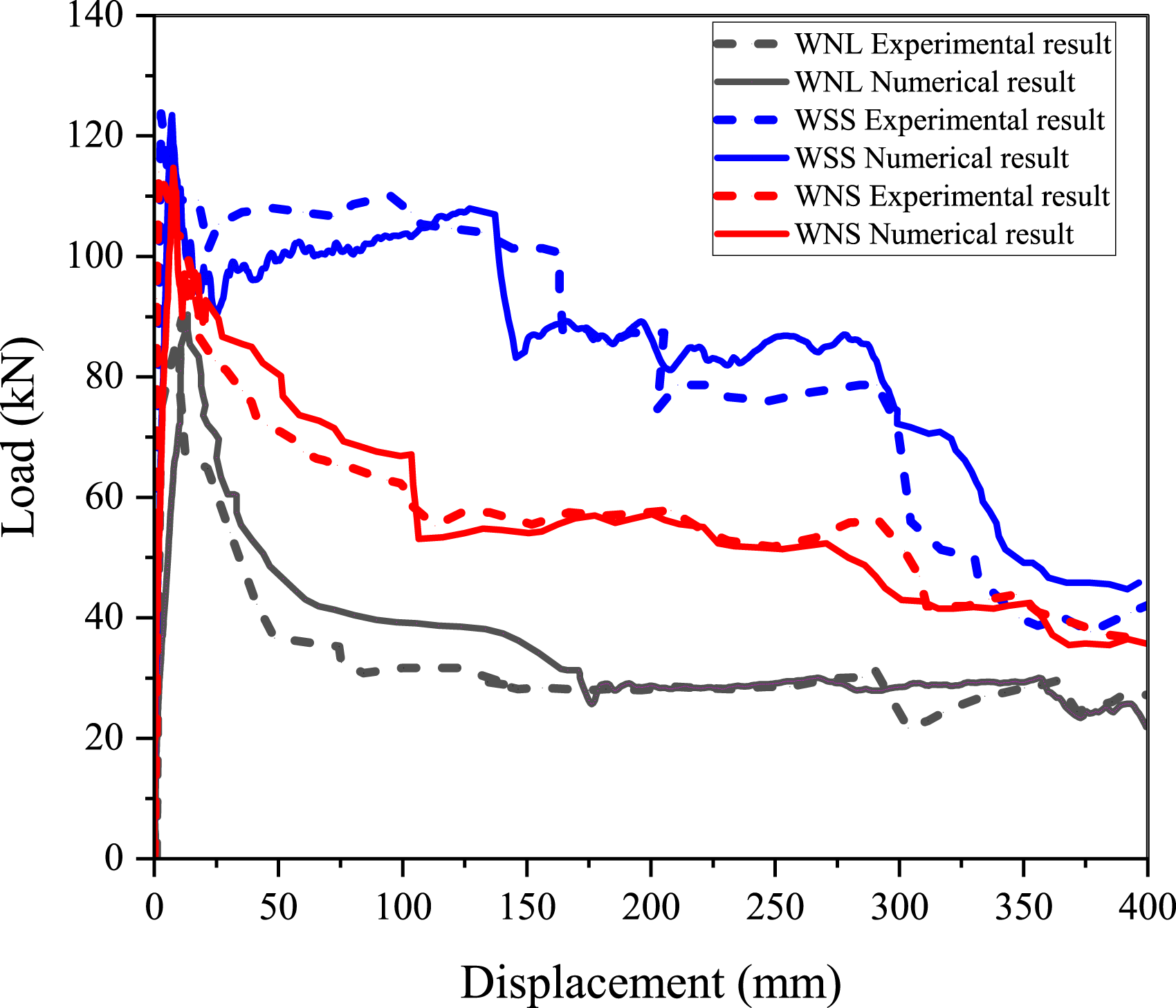
The failure patterns of the three specimens are given in Figure 4. Even though CSCM cannot monitor concrete cracks, effective plastic strains, which represent the damage of concrete, can be used as an alternative since wider cracks correspond to greater tensile damage of concrete (Di Trapani et al., 2018; Palmisano and Vitone, 2015). The pattern of effective plastic strains can roughly depict the fracture patterns of RC frames. The ultimate failure modes at the wall panels and beams simulated by the numerical results match well with experimental findings, indicating that the FE models are reasonable and reliable for studying the progressive collapse behavior of RC frames with infilled masonry. Failure pattern of infilled frames subjected to CRS.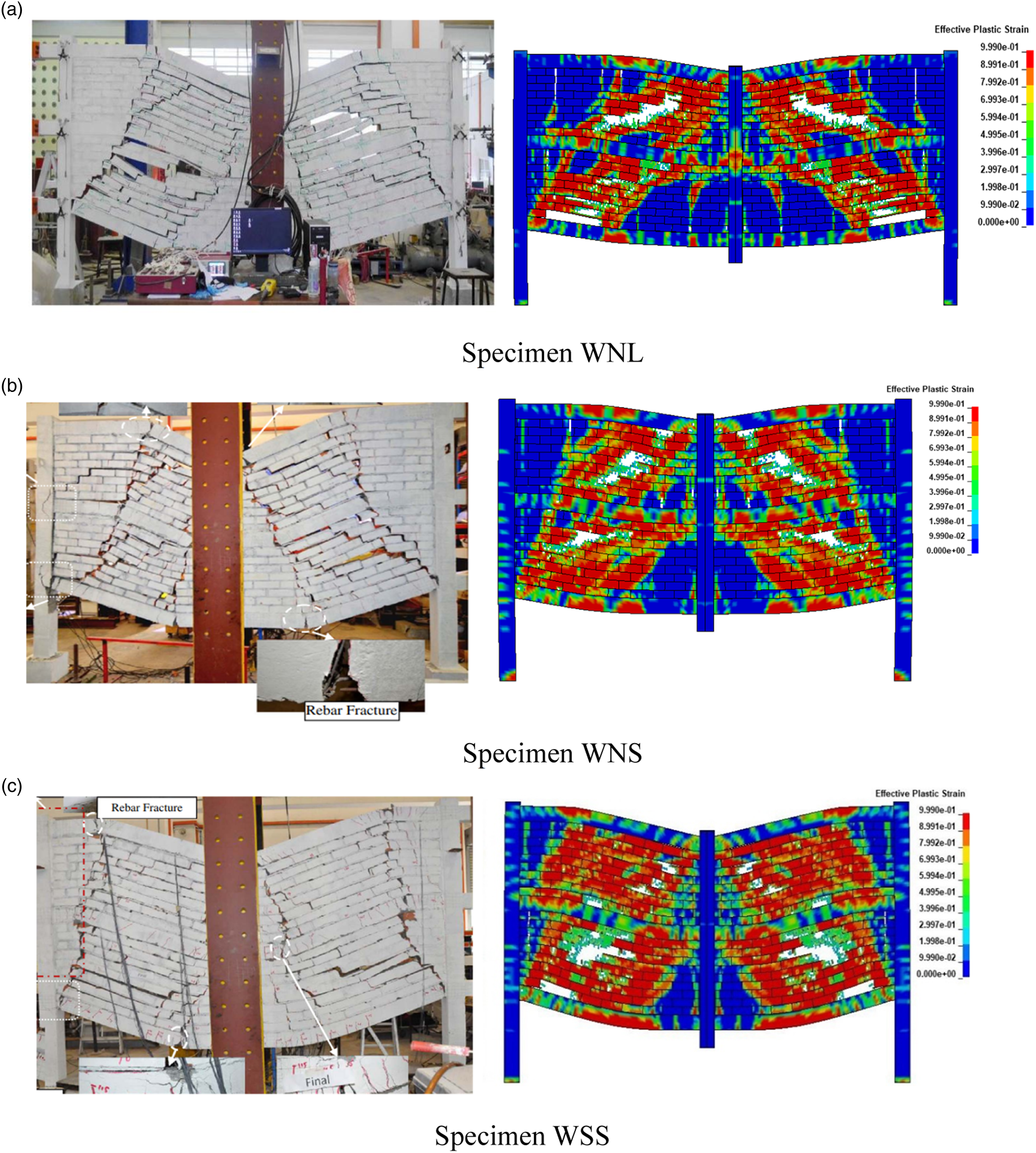
Modeling of RC infilled frame having tie columns
Finite element modeling
According to the Chinese practice and code (GB 50011-2010, 2016), for a wall longer than 5 m or the height of the two story, the tie column should be set in the wall. In the current numerical study, specimen WNL which is non-seismically designed infilled frame with clear span of 2250 mm is considered as a reference because the prototype of the single wall panel was 9 m in length, which was longer than 5 m and should include a tie column in practice. Moreover, in practice the cross-sectional dimensions of the tie column should be equal to the wall thickness, the longitudinal reinforcement should be four bars with diameter ranging from 12 mm to 16 mm, and the bars with diameter of 6 mm should be used for stirrups with a spacing of 200–250 mm.
Accordingly, in the new designed RC IFFT, the dimensions and structural detailing of the tie column is constructed (on 1/4 scaled) as per Chinese code. Figure 5 shows the FE model of the IFFT. For a tie column, four bars with 3 mm diameter at the section corners are used as longitudinal bars and stirrups having 3 mm diameter are provided at the spacing of 50 mm. The clear cover provided was 7 mm. Detailing for the tie column is shown in Figure 5. The toothing technique is used for the connection between CMUs and the tie column to ensure adequate connection strength. The spacing and height of toothing is taken equal to the height of a CMU. Numerical model of IFFT (unit: mm).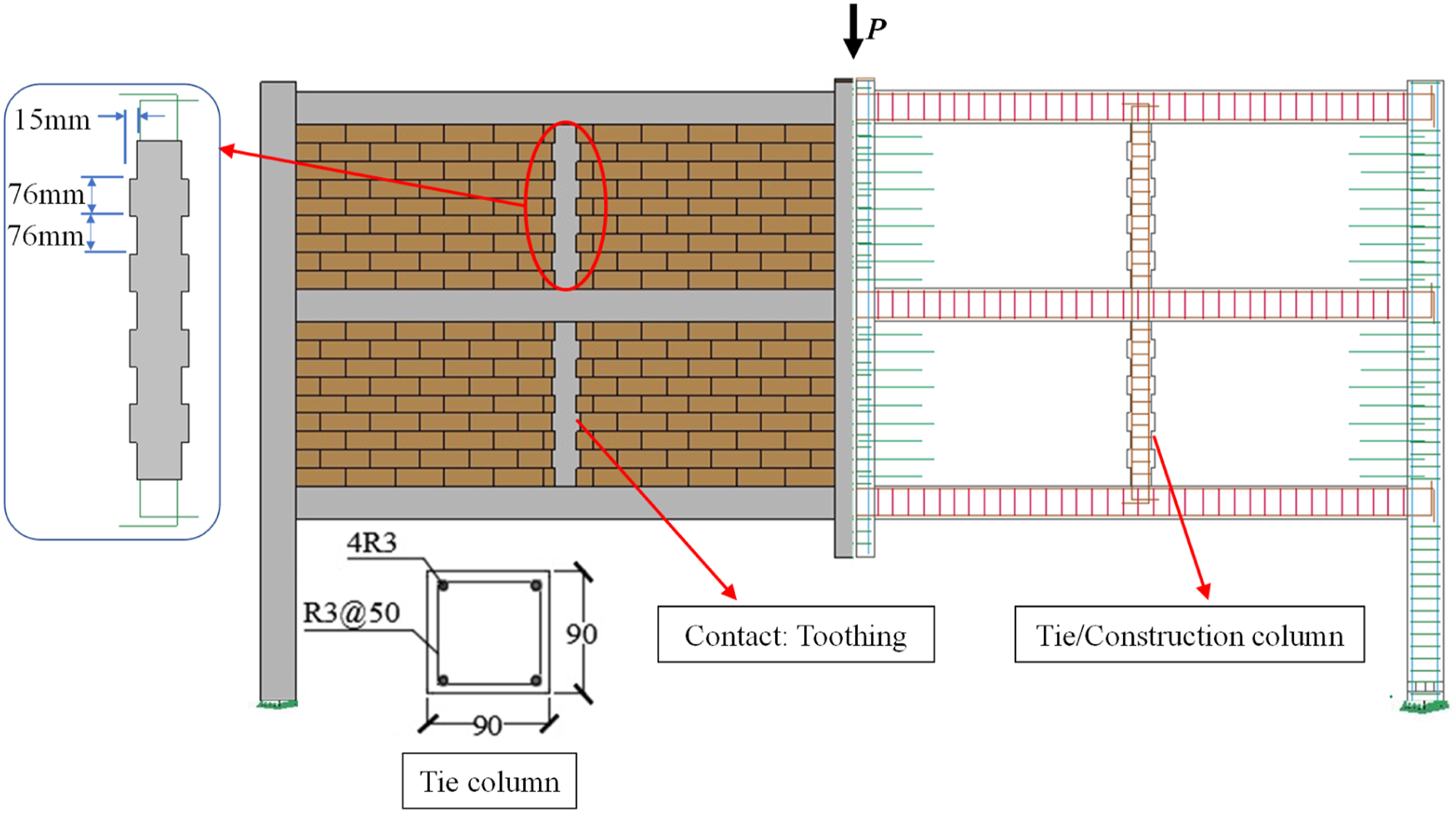
Analysis of IFFT
For simplicity of description and comparison, the numerical model of specimen WNL is denoted as IFF (infilled frame with not tie columns). The stress contours of IFF and IFFT at various displacements are demonstrated in Figure 6. Without a tie column, each wall panel has a single diagonal strut that carries most of the load, and the beams connected to those struts function as ties to balance diagonal compression. When the wall span is large, the diagonal angle with respect to the horizontal line is smaller, resulting in the vertical component of the strut in resisting the gravity load becomes smaller and less effective. In comparison, with a tie column in the wall panel, the load transfer path is also a truss mechanism, but it is improved in twofold: (1) tie columns function as additional ties and more CMUs in wall panels are mobilized in compression as struts; (2) the inclined angles of struts are increased in each sub-panel to improve the vertical components of struts in resisting gravity load. Through the above ways, the compression strength of infill walls can be more fully used to resist progressive collapse. Stress contours at the middle column displacement of 6.5 mm.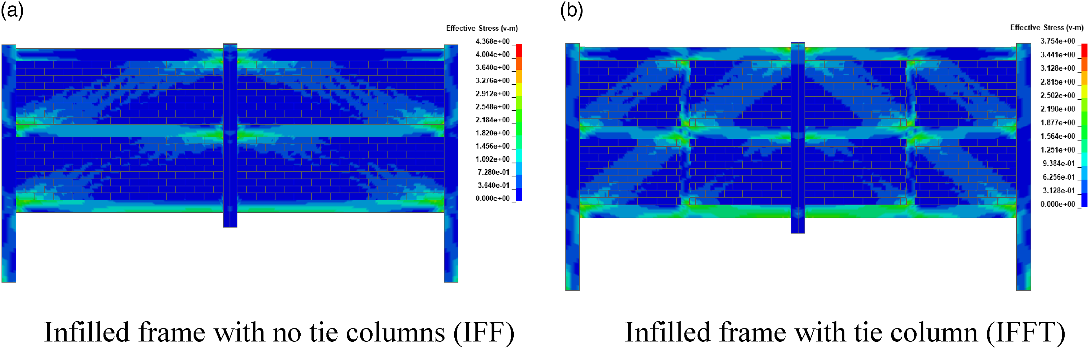
As shown in Figure 7(a), with increasing the middle column displacement, failure is initiated from the masonry wall. It is observed that the integrity of wall is increased due to the presence of tie columns and crack redistribution has occurred. Then by further increasing the displacement to 150 mm, a tensile failure starts in the tie columns, as indicated in Figure 7(b). Similarly, Figure 7(c) shows that finally collapse occurs when the beam fails with the fracture of longitudinal reinforcement. Strain contours of IFF and IFFT at different displacements.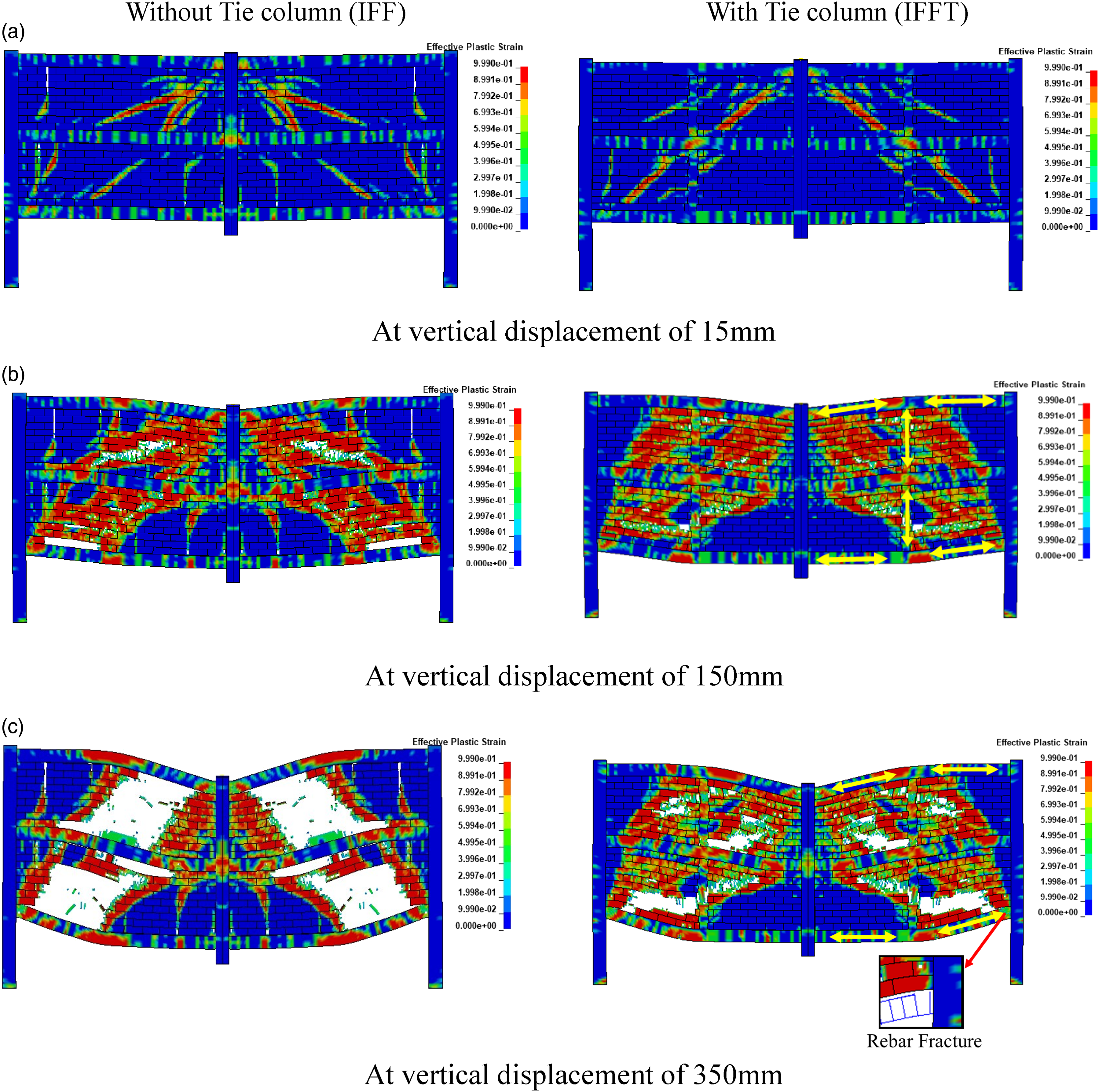
Figure 8 shows the progressive collapse resistance of IFFT and IFF. At first, the load carrying capacity increases with increasing the displacement for both IFF and IFFT. It is clearly seen that the first peak load capacity of the IFFT reaches 112 kN, which is around 26% greater than the one of IFF (88.5 kN). Secondly, the initial stiffness of IFFT has increased from 26 × 103 kN/m to 31 × 103 kN/m (up by 19.2%) due to the presence of the tie columns. After the peak load, the structural resistance of IFF drops sharply due to strut failure. In contrast, the post-peak resistance of IFFT drops more smoothly, mainly because the load transfer paths are more uniformly distributed in infill walls with the contribution of tie columns. For example, at the displacement of 100 mm, the structural resistance of IFFT is about 125% greater than that of IFF. At the final stage, the load reaches 30 kN at the displacement of 400 mm for both the specimens. Comparison of progressive collapse resistance of IFFT and IFF.
Parametric studies on progressive collapse resistance of IFFT
The main variations of IFFT include number of stories, span length and rebar size of tie-columns etc. To study the influence of the aforementioned variables on the progressive collapse resistance of IFFT, three series of frames have been studied for each parameter in this Section. Moreover, analysis is performed on two sets of infilled frames with and without tie columns, in which only one of the above-mentioned parameters varies whereas the remaining geometric and material properties stay unaltered.
Effect of the number of stories
For assessing the sensitivity of the number of stories on the progressive collapse resistance, the frames with 3, 5 and 7 story infilled frames with and without tie columns are studied, in which the ground story contains no infill walls. Among them, the modeling information of the 3-story IFF is the same as those demonstrated in the previous sections. The geometric and material properties of 5- and 7-story infilled frames are identical to those of 3-story frame.
Figure 9 shows the progressive collapse resistance of IFF and IFFT having 3-, 5- and 7-stories. It is evident that the progressive collapse resistance increases with increasing the number of stories. The maximum resistance for 3-story IFF is 88.5 kN, whereas the maximum resistance for the same 3-story IFFT is about 112 kN. Similarly, the peak resistance of 5-story (7-story) IFFT and IFF is approximately 255 kN (388 kN) and 185 kN (267 kN), respectively. In a word, after inserting a tie column at the mid-span of each wall panel, the peak progressive collapse resistance has increased by about 26%, 38% and 45% for 3-, 5- and 7-story infilled RC frame, respectively. This suggests that by adding the number of stories, the additional contribution of tie columns on structural resistance against progressive collapse gradually increases. Progressive collapse resistance of IFF and IFFT having 3-, 5- and 7-stories.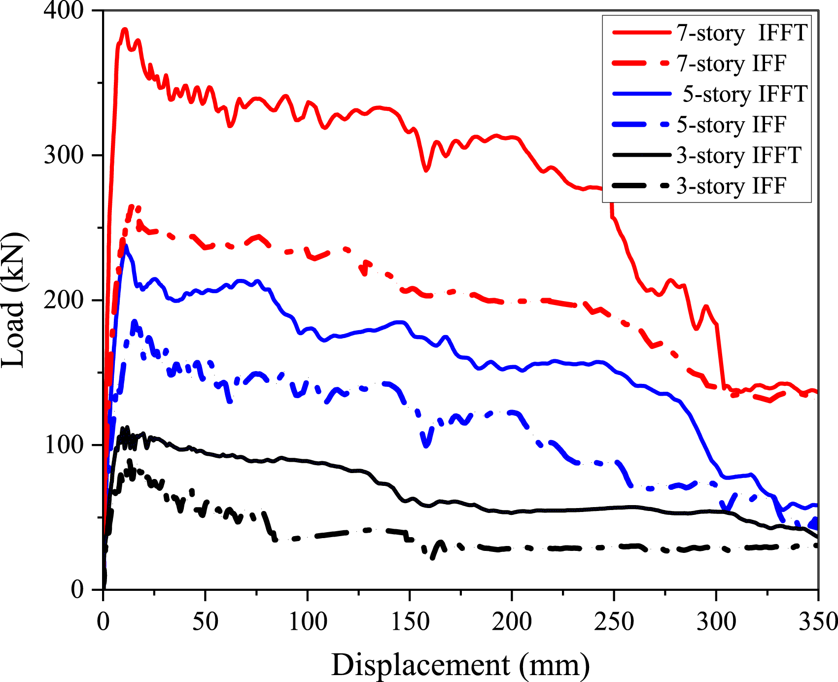
Effect of span length
On top of the 3-story RC infilled frames, six 1/4 scaled frames with and without tie columns are investigated, and the concerned span length is S1 = 1500 mm, S2 = 1875 mm and S3 = 2250 mm respectively, whereas the other geometric and material properties are unaltered.
Figure 10 shows that the overall resistance against progressive collapse of IFFT is greater than that of IFF at each span length, in particular at the post-peak stage. For a frame having span S1, the peak resistance of IFFT-S1 and IFF-S1 is about 145 kN and 133 kN, respectively. Similarly, the resistance of IFFT and IFF having span equal to S2 (S3) is 120 kN (112 kN) and 106 kN (88.5 kN), respectively. It shows that inserting tie columns are able to increase the peak progressive collapse resistance by around 9%, 13% and 26% for the frames with span S1, S2 and S3, respectively, suggesting that the effect of tie column is more significant in the IFF with longer span. In other words, as recommended by the Chinese codes (GB 5001-2010, 2016), it is reasonable to add a tie column when span increases from 5 m. In addition, based on the analysis above, if span is greater, then the beneficial effect of a tie column will be greater. Progressive collapse resistance curves of 3-story-IFF and IFFT having different span length.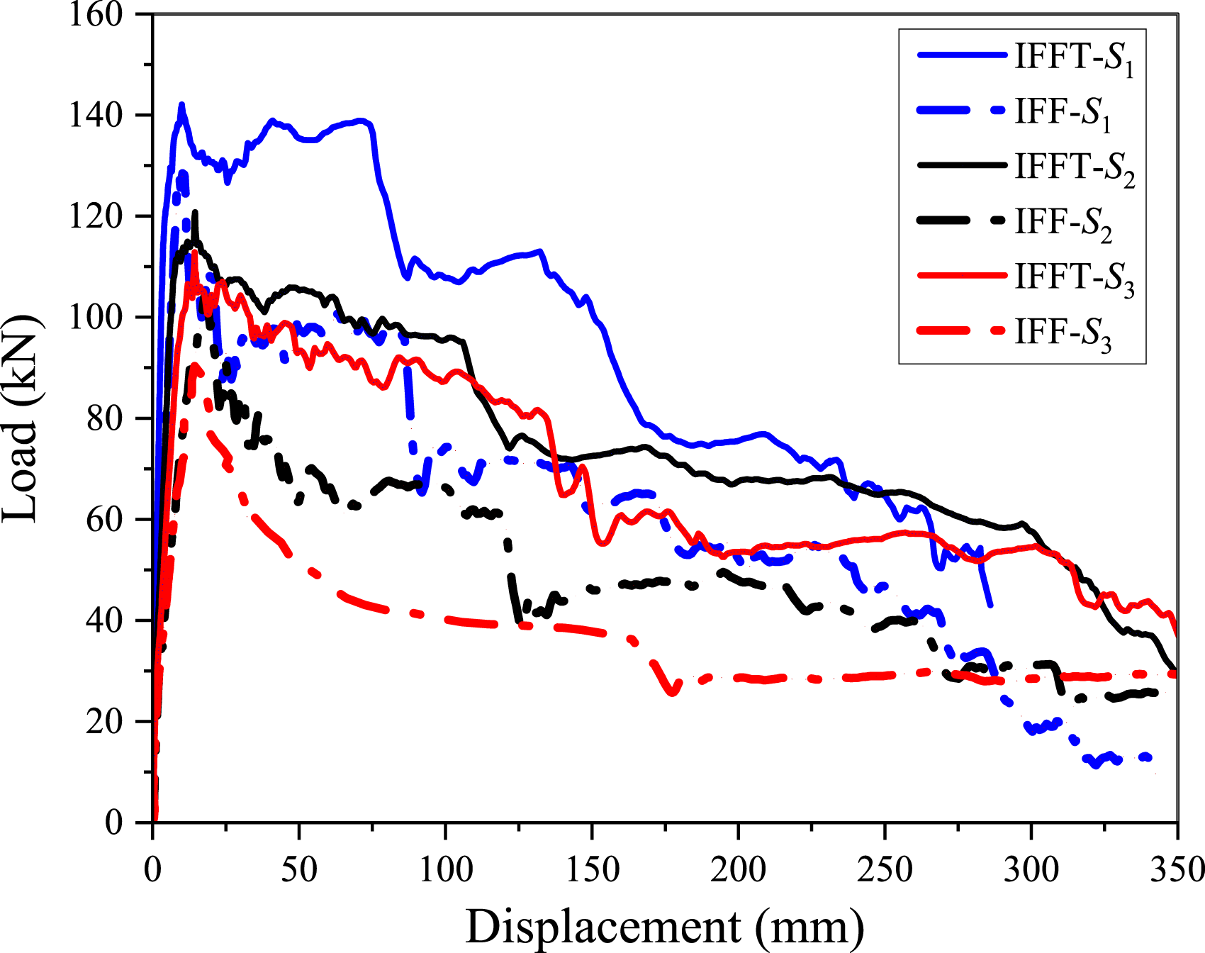
Effect of longitudinal reinforcement ratio of tie column
In the 3-story IFFT, the effect of longitudinal reinforcement of tie columns is studied through varying the bar diameter, by taking reinforcement ratios of ρ1 = 0.24%, ρ2 = 0.62% and ρ3 = 0.97% (by using 10-, 16- and 20-mm diameter bars). The corresponding structural resistance against progressive collapse is demonstrated in Figure 11. It is seen that enlarging the longitudinal reinforcement ratio of tie column improves the progressive collapse resistance of IFFT. For instance, the peak resistance for frames with ρ1, ρ2 and ρ3 is about 112, 124 and 139 kN, respectively. In a word, increasing the longitudinal reinforcement ratio by 156% and 300% can only enhance the structural capacity by around 10.7% and 24.1%, respectively, suggesting that further increasing reinforcement ratio of tie column larger than around 0.24% is not an effective method to enhance the resistance against progressive collapse. This is because the failure mode is dominated by the diagonal compression failure of infill walls rather than tension failure of the tie columns. However, the post-peak resistance can be more effectively enlarged with a larger reinforcement ratio of tie columns. Progressive collapse resistance of IFFT with different longitudinal reinforcement ratio of the tie column.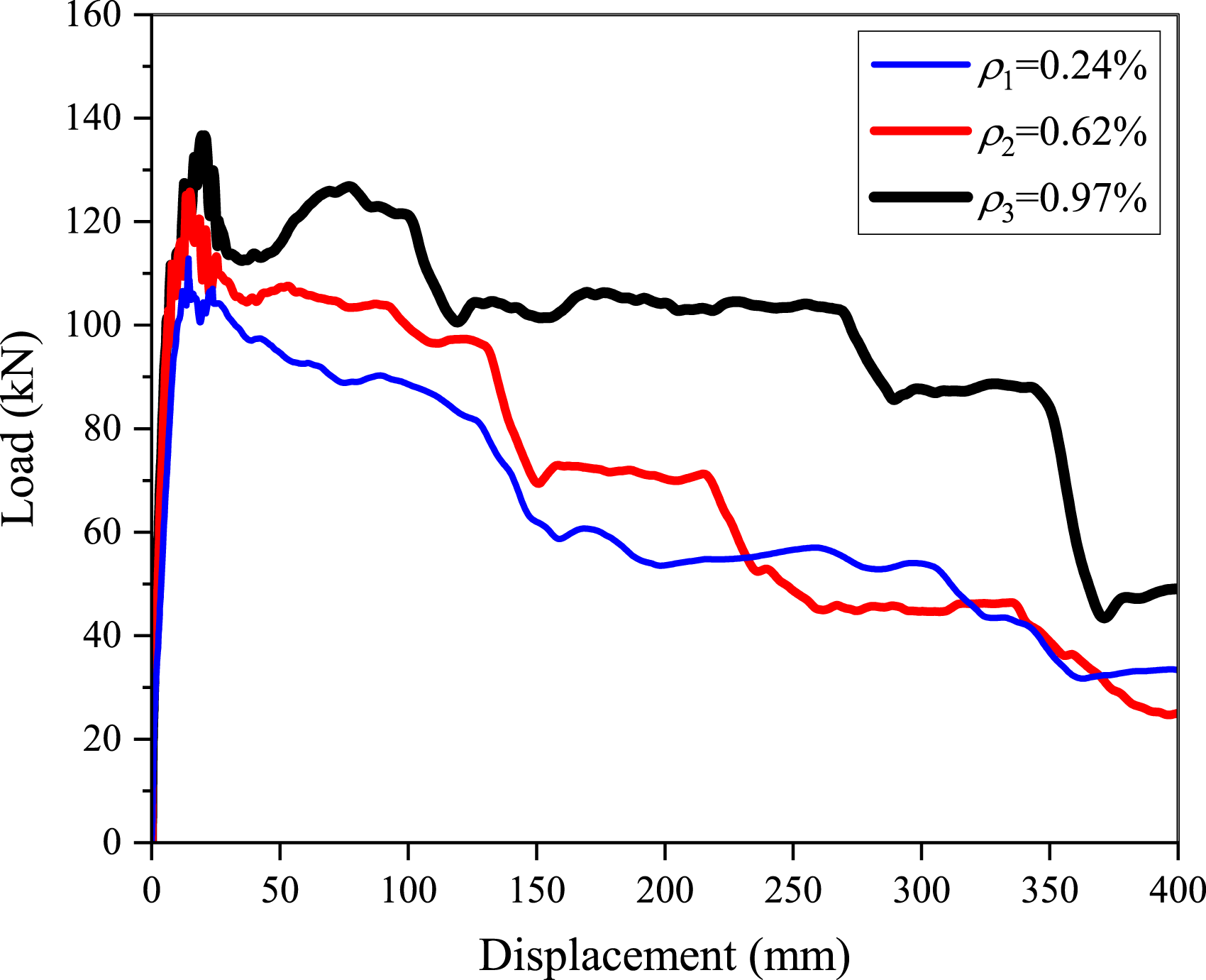
Figure 12(a) shows that when the reinforcement ratio of the tie column is 0.24%, tensile failure of the tie columns at the first story (TC1-1 and TC2-1) due to fracture of longitudinal bars happens before beam failure. When the reinforcement ratio is increased to 0.62%, tensile failure of tie columns at the second story (TC1-2 and TC2-2) as well as beam failure due to bar fracture at the first story both occurred, as shown in Figure 12(b). Moreover, when the reinforcement ratio of the tie column is further increased to 0.97%, as shown in Figure 12(c), the beams at the first story (B1-1 and B2-1) fails prior to the tie column. Failure modes of IFFT with various reinforcement ratios of tie columns.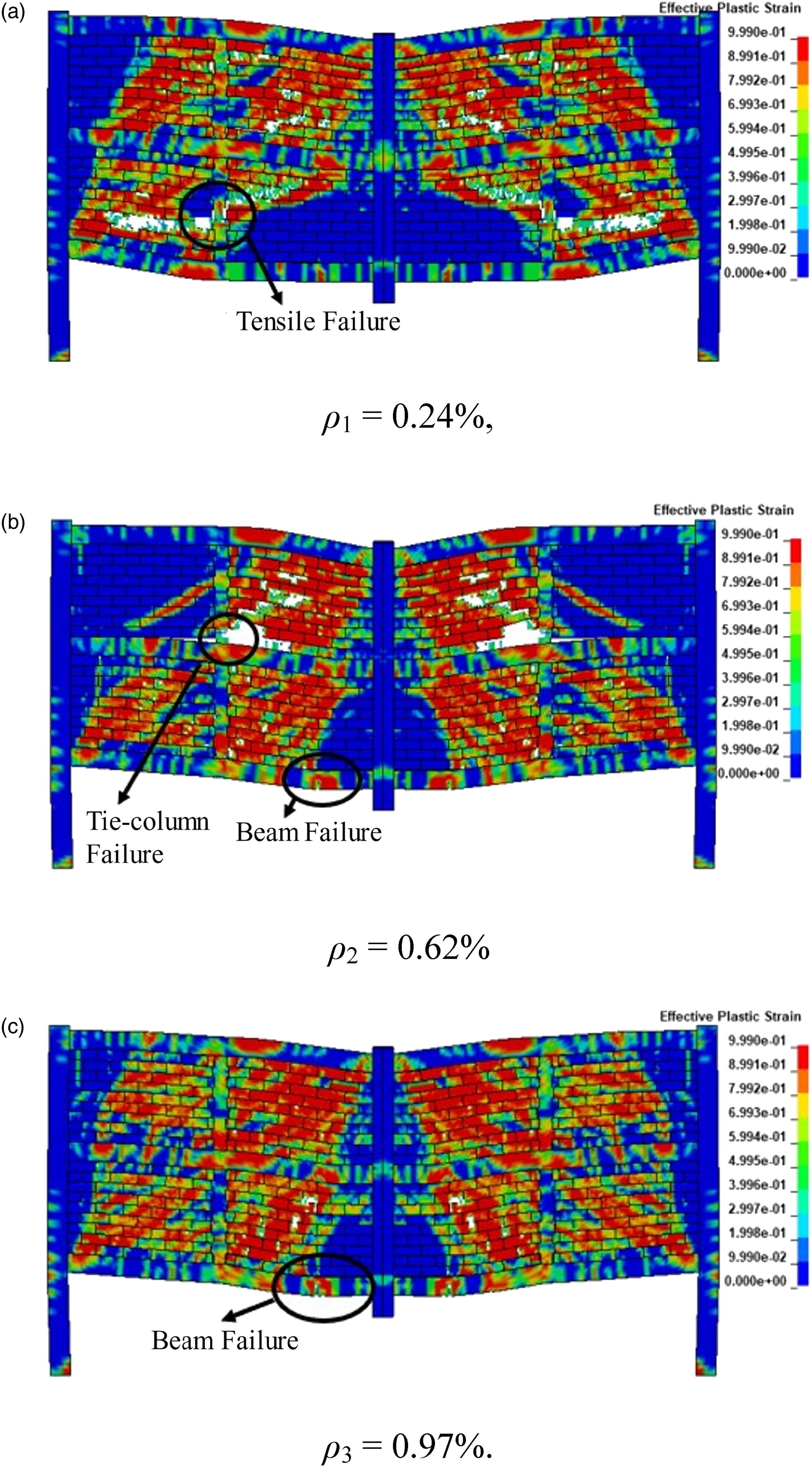
Macro-model of IFFT
The high-fidelity-based numerical model (also called as micro-model) is able to clearly demonstrate the load transfer path and failure modes of RC infilled frames. However, in overall structural analysis, micro-model is preferred due to high computational efficiency, in which the infill walls are equivalently represented by struts. For infilled frames without tie columns, several types of macro-models have been proposed (Di Trapani et al., 2018; Li et al., 2016; Yu et al., 2021) and implemented in structural analysis (Feng et al., 2022). Similarly, it is imperative to propose macro-model for IFFT as well.
Compared with bare frames, the presence of infill walls significantly enhances the stiffness and the first peak capacity of infilled frames against progressive collapse. Moreover, the peak capacity is obtained at very small deformation, typically at 9% of the beam depth. Therefore, with the first peak capacity as the main concern, stress contour at small deformation prior to the damage of the infill walls is very critical to visualize the load transfer path, which can be further used to construct the equivalent truss. Accordingly, Figure 13 demonstrates the stress contour of the IFFT under a middle CRS, and the corresponding macro-models are proposed as well, in which sub-panels of the infill walls work as diagonal struts and tie columns function as ties. It is evident that the tie columns make the truss more fully mobilized in the infilled frames. Load transfer path and proposed macro-model of IFFT.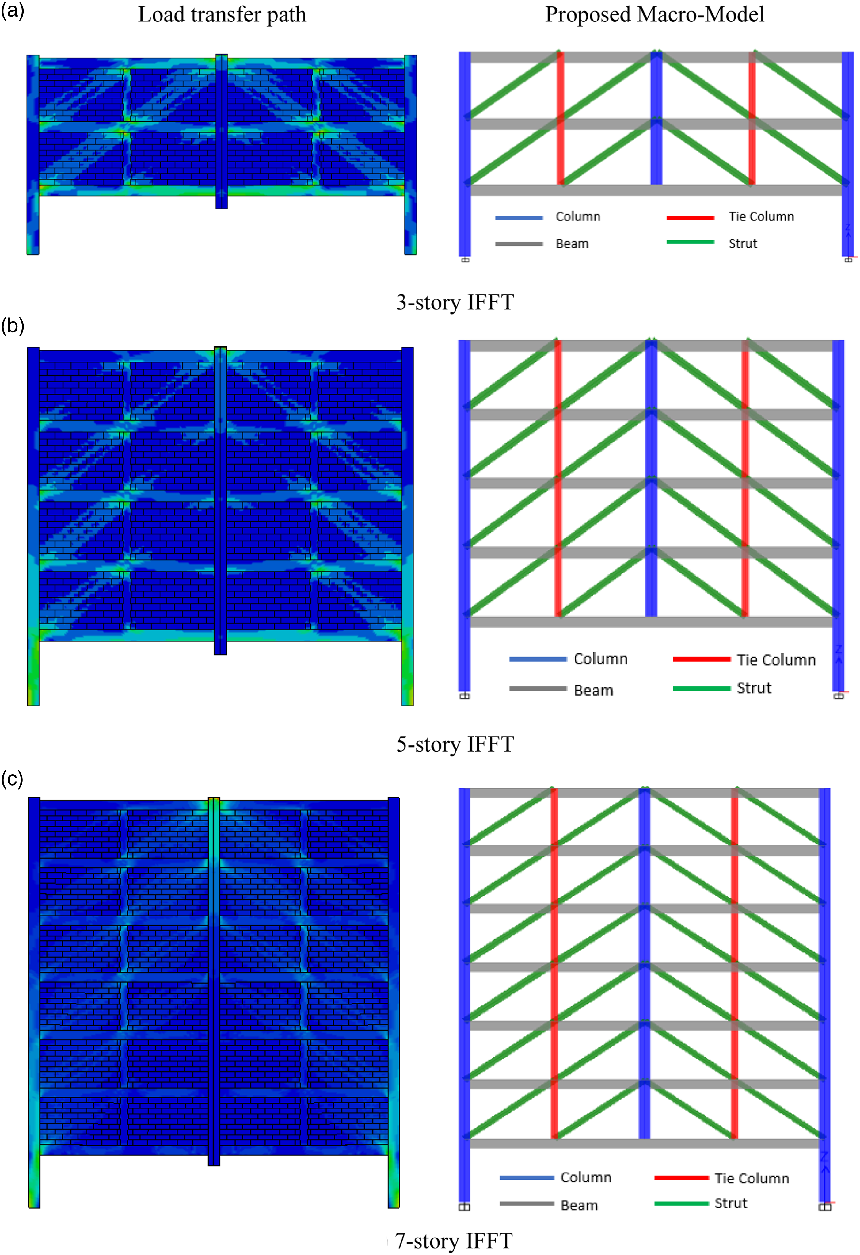
After proposing the macro-models of IFFT, it is essential to verify the accuracy of the macro-models. For this purpose, the macro-models corresponding to the infilled frames with 3, 5 and 7 stories as shown in Figure 13 are analyzed under a middle CRS. In the macro-models, fiber-based beam elements are used for beams, columns and struts. Fiber sections of various members are shown in Figure 14. Fiber Sections of structural members (unit: mm).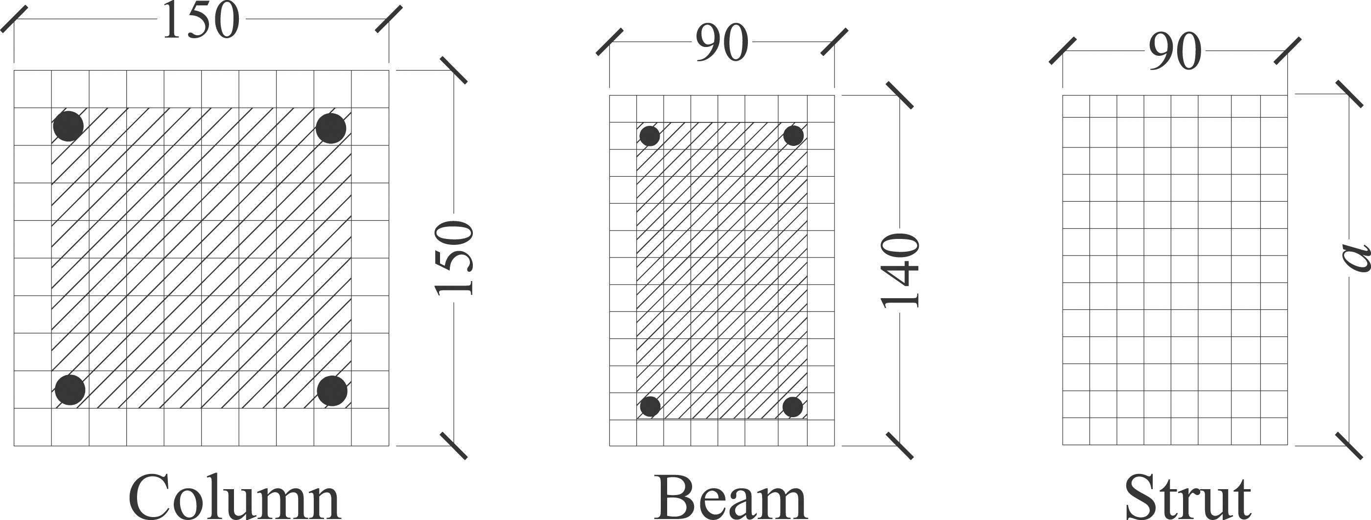
Moreover, during modeling the behavior of equivalent struts and ties, Hughes-Liu element was used. For each fiber at a discretized cross-section, uniaxial material properties are specified with MAT_PLASTICITY_COMPRESSION_TENSION. Reinforcement bars are represented with elastic-plastic-hardening behavior, and the material strengths are listed in Table 1. A bi-linear stress-strain curve is used and bar fracture occurs after attaining the ultimate tensile strength, as shown in Figure 15(a). The uniaxial compressive and tensile stress-strain curve of concrete is shown in Figure 15(b), in which the compressive branch curve is calculated with the Mander’s model (1988) and the tensile behavior is described by a bilinear curve. For CMU strut as seen in Figure 15(c), only compressive strength is considered and the uniaxial stress strain curve is determined according to Di Trapani et al.’s work (2021). Stress Strain models of different materials and members.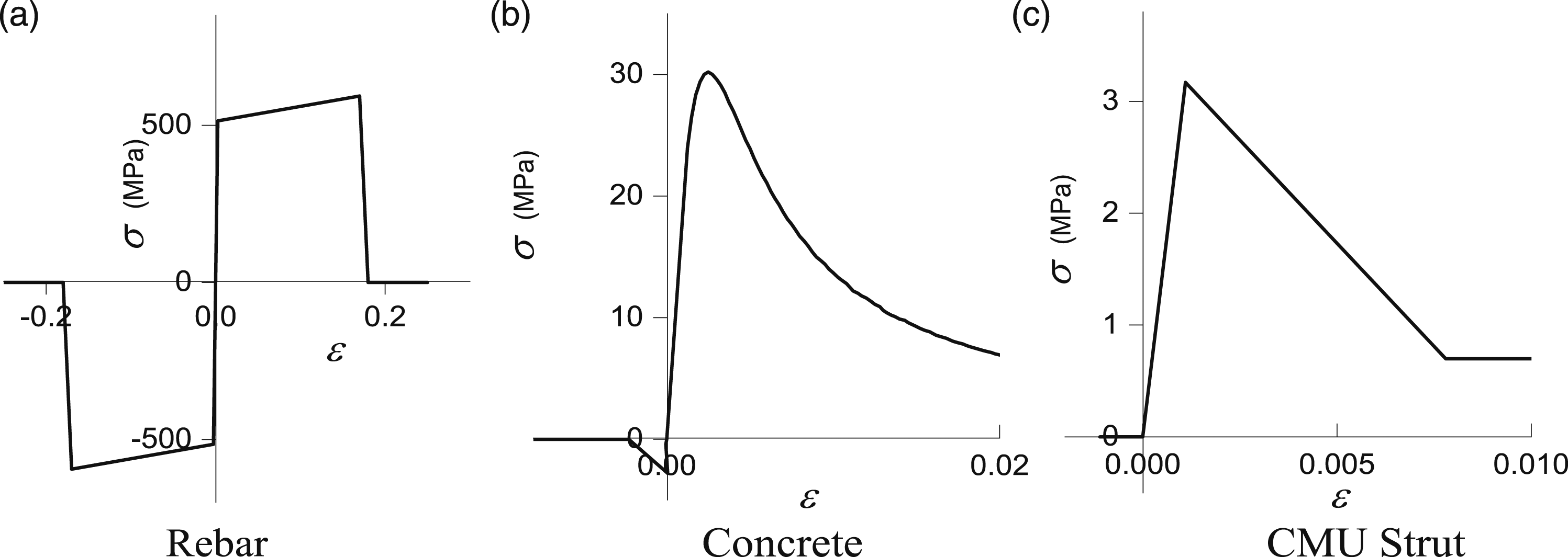
For equivalent diagonal struts, the width and the compressive strength for each infill zone is proposed according to Di Trapani et al. (2018). The width (a) of equivalent strut, as shown in Figure 16, is calculated using equation (1), and the strut thickness (t) is taken as the thickness of masonry wall. Parameters for the width of equivalent compressive struts for infill walls.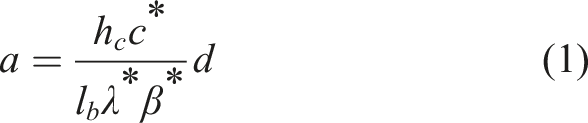
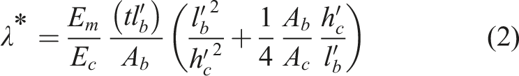
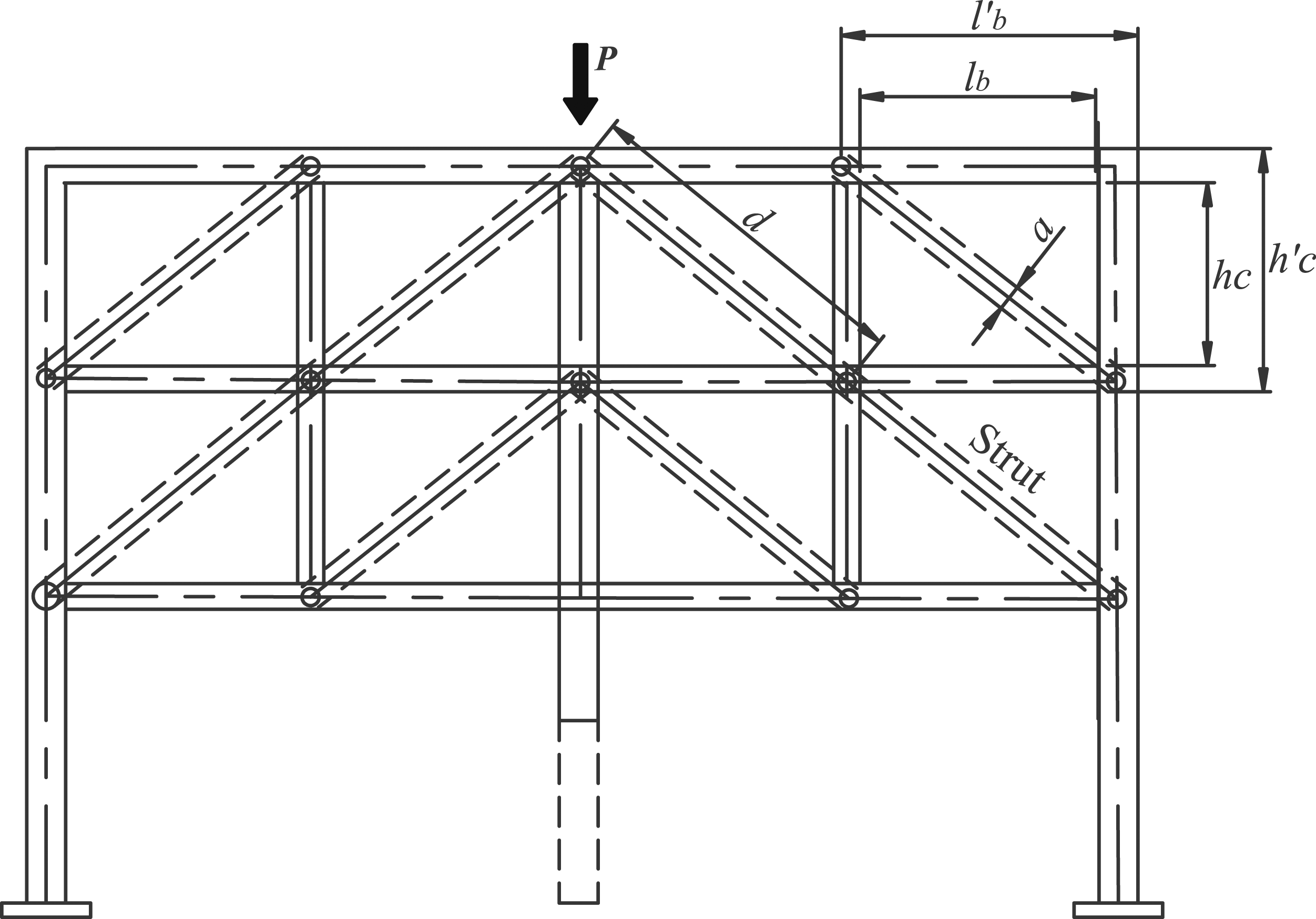
The geometric parameters are shown in Figure 16. Ab and Ac represent the cross sections of beams and columns, respectively; Ec stands for the elastic modulus of the concrete frame, and Em the conventional elastic modulus that accounts for the Young’s moduli Em1 and Em2 of masonry along the two orthogonal directions as given by equation (3).
For the compressive properties of diagonal struts of the infill walls, equations (4)–(7) provide the peak and ultimate strengths (fmd0, fmdu), peak and ultimate strains (εmd0, εmdu).


Calculated parameters for compression strut.
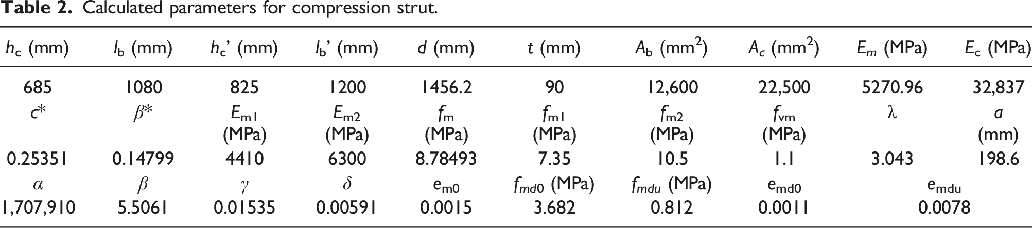
Figure 17 demonstrates the structural resistance of IFFT with 3-, 5- and 7- stories through macro-model analysis and micro-model analysis. In the case of 3-, 5- and 7- stories, the ratio of macro to micro-modal analysis peak capacity is 0.961, 1.045, and 0.989, respectively. The results show good agreement between macro-model analysis and micro-model, suggesting that the current macro-model scheme is reasonable. As a result, the proposed macro-model can be further implemented in overall structural analysis with infill walls having tie columns. Comparison of structural resistance of IFFT with macro-model and micro-model.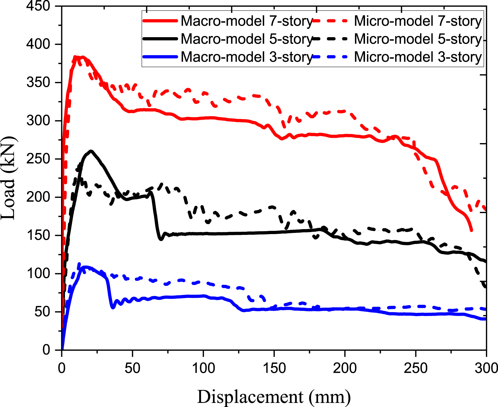
Case study with macro-model for infills
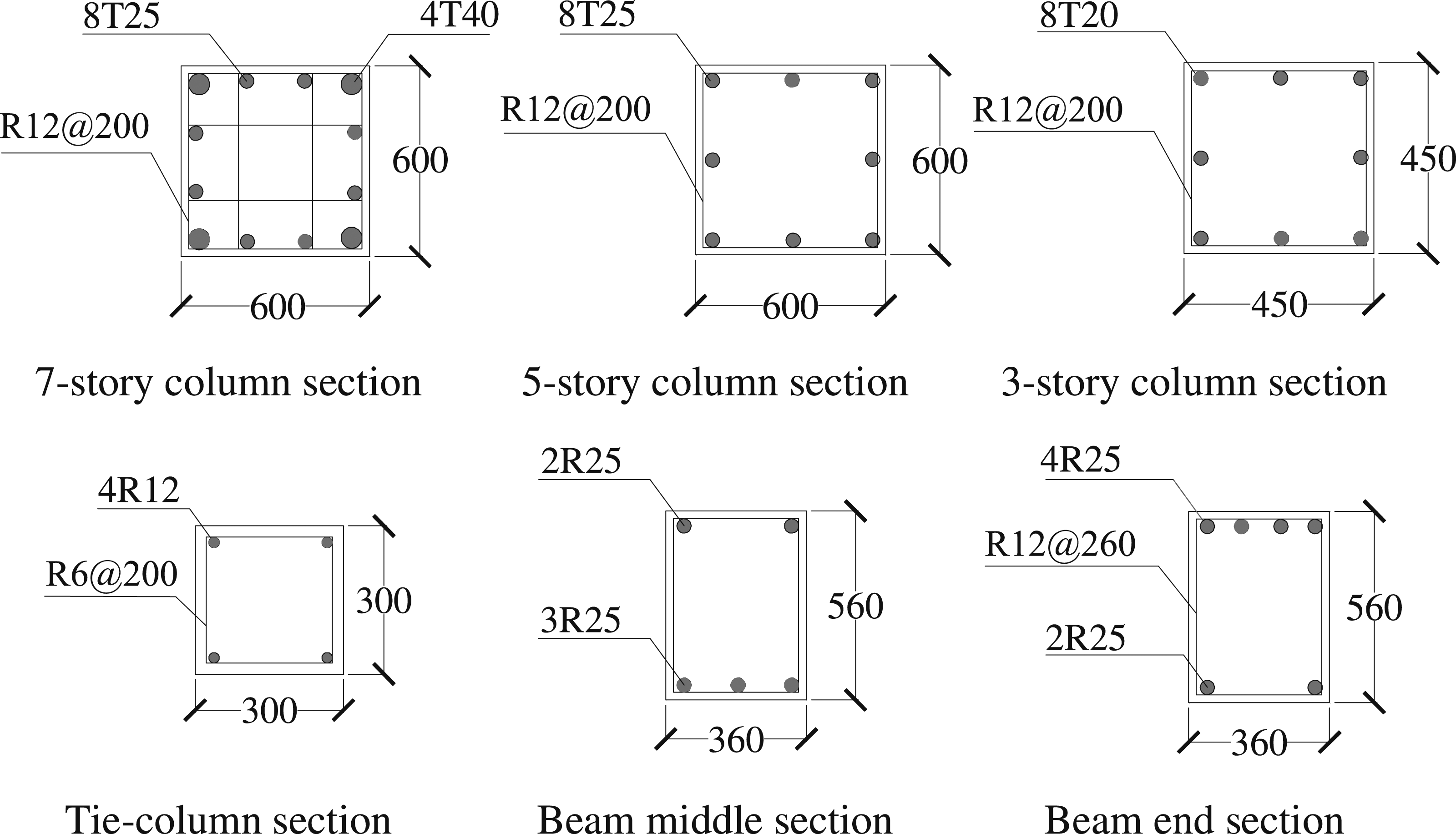
A case study was performed to implement the macro-model and examine the effect of tie column on the progressive collapse response under CRS. Seven-story, five-story and three-story structures were used as an example and their design was carried out according to ACI 318-14 (2014). Height of the ground story and the other standard stories were taken as 3600 mm and 3300 mm, respectively. The span length of both orthogonal directions was taken as 7200 mm. The geometry of seven story infilled frame is shown in Figure 18. The design dead load and live load were considered as 2.4 kN/m2 plus self-weight and 2.0 kN/m2, respectively. The cross-sectional dimensions of beam and column were 360 mm × 560 mm and 600 mm × 600 mm, respectively. The dimensions of tie columns in IFFT were 300 mm × 300 mm. Compressive strength and yield strength of concrete and steel bars were taken as 30 MPa and 450 MPa, respectively. Figure 19 show the reinforcement details of beams, columns and tie columns. Geometry of Seven story infilled frame structure (Units: mm). Reinforcement details (Units in mm).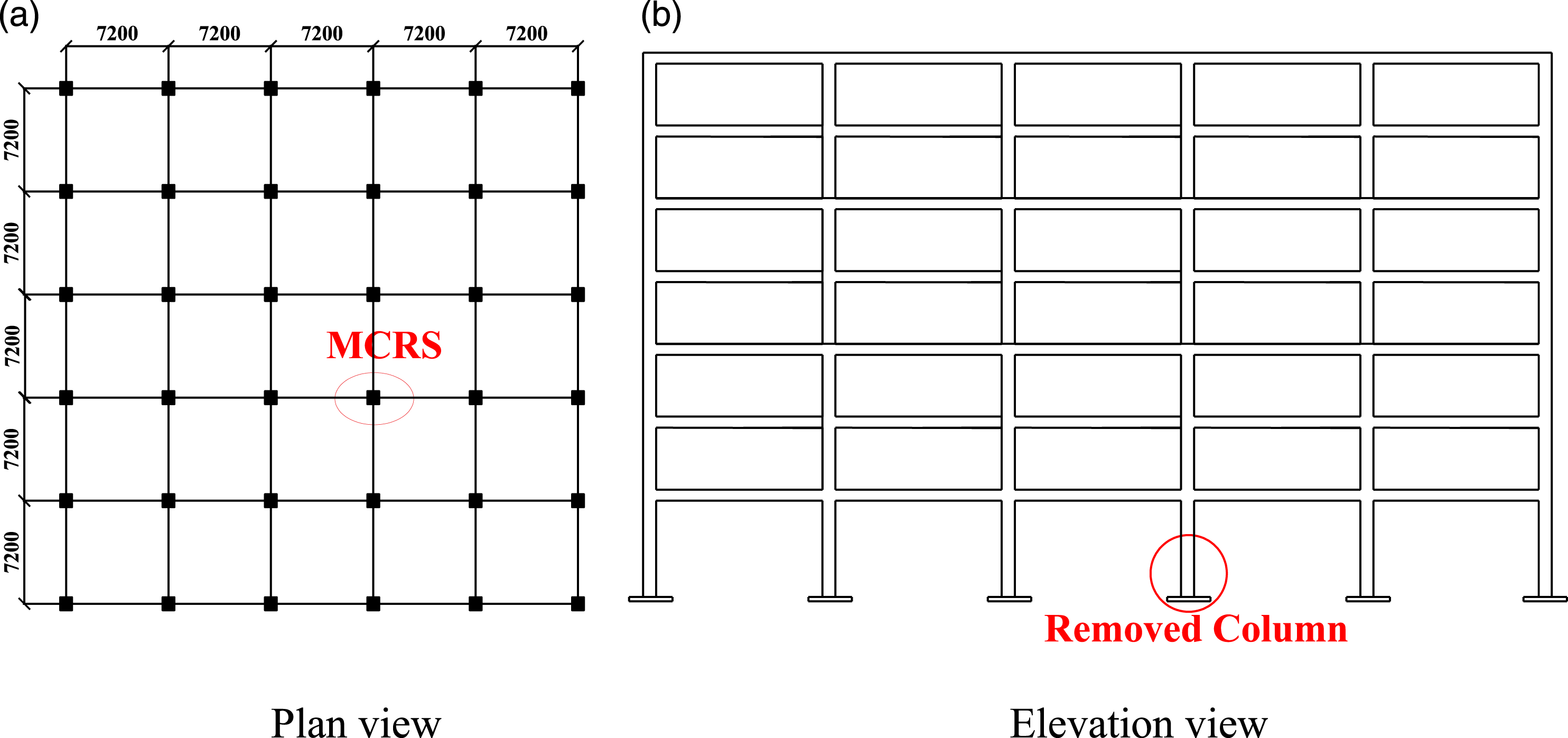
The proposed model presented in the previous section was adopted to model the infills just directly above the removed column, and the other infills were modeled with conventional two diagonal strut model, as shown in Figure 20(a). To demonstrate the effect of the tie columns, an IFF was considered as well. The infill walls of IFF was modeled according to method proposed by Di Trapani et al. (2018), in which three struts per each panel were considered for the infills directly above the removed column, whereas the other infills were modeled using a conventional equivalent strut model, as shown in Figure 20(b). In comparison, the seven-story, five-story and three-story IFFT is denoted as IFFT-7, IFFT-5 and IFFT-3, and similarly, the seven-story, five-story and three-story IFF is denoted as IFF-7, IFF-5 and IFF-3. The geometrical properties and calculated parameters for infill walls of IFFT and IFF are given in the Table 3. Macro-model of seven-story infilled RC frame structures. Mechanical and geometric properties of masonry struts of the IFFT and IFF.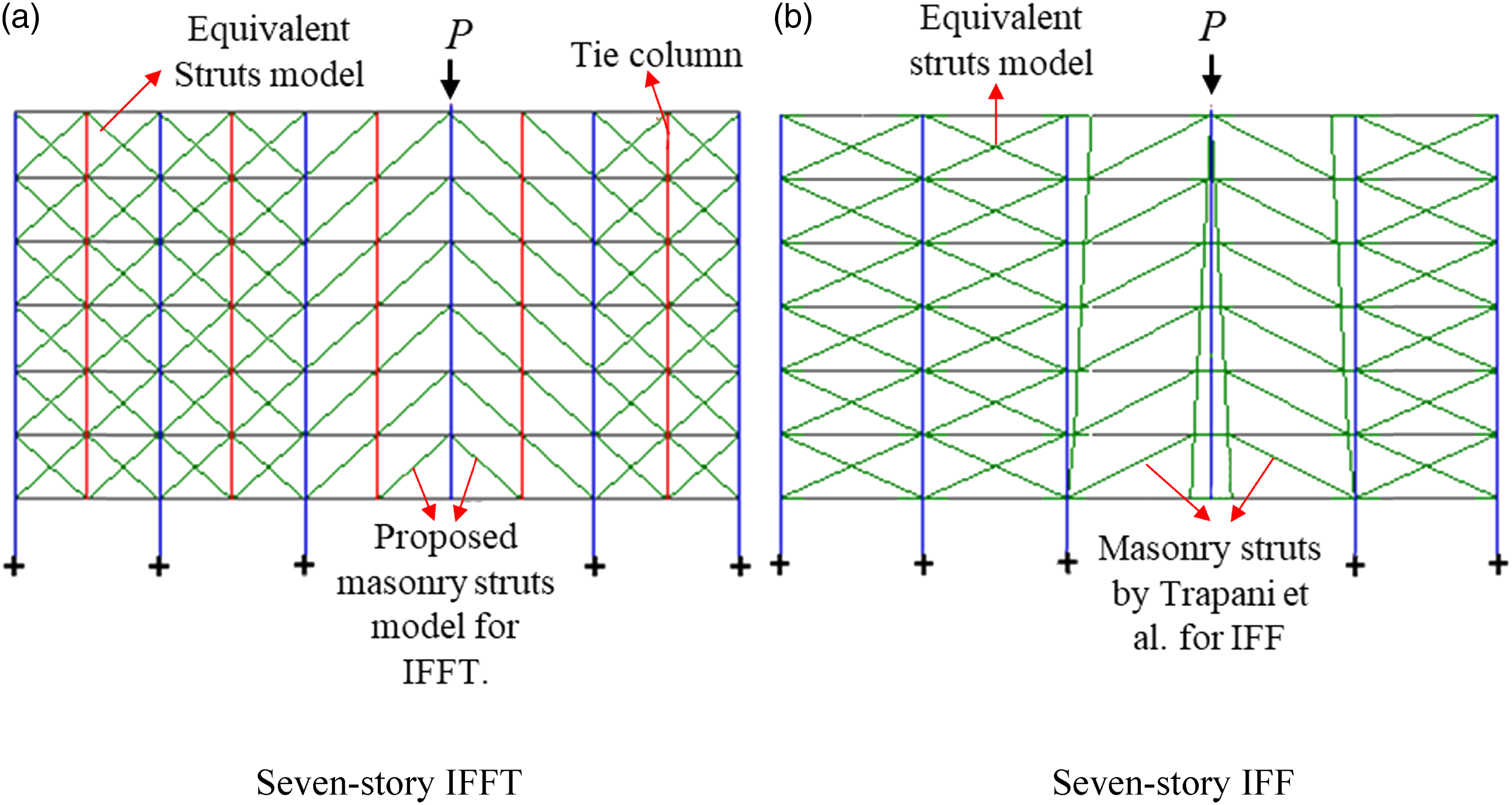
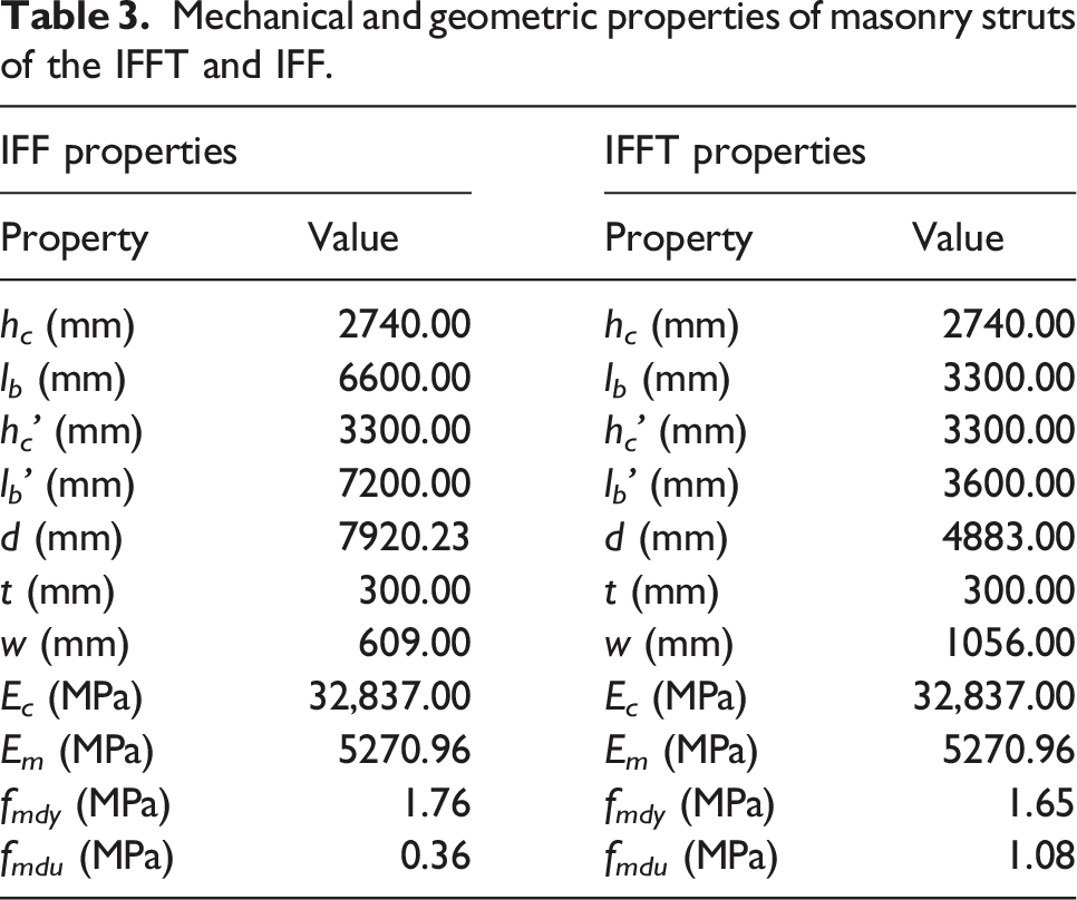
Figure 21 demonstrates the progressive collapse resistance of the case studies. It is found that the progressive collapse resistance is increased with inserting tie columns, in particular for the peak capacity. For instance, the peak capacity for 7-story, 5-story and 3-story IFFT is 8170, 5288 and 2655 kN, respectively. In comparison, the peak capacity for the same 7-story, 5-story and 3-story IFF is about 5105, 3531 and 1891 kN, respectively. In a word, after inserting a tie column at the mid-span of the wall panel, the peak progressive collapse resistance has increased by approximately 64%, 49% and 41% for 7-, 5- and 3-story infilled RC frame, respectively. Moreover, a noticeable increase in the stiffness is also observed, such that the initial stiffness is increased by about more than 300% for all IFFTs with seven stories, five stories, and three stories. Progressive collapse resistance of IFF and IFFT under middle CRS.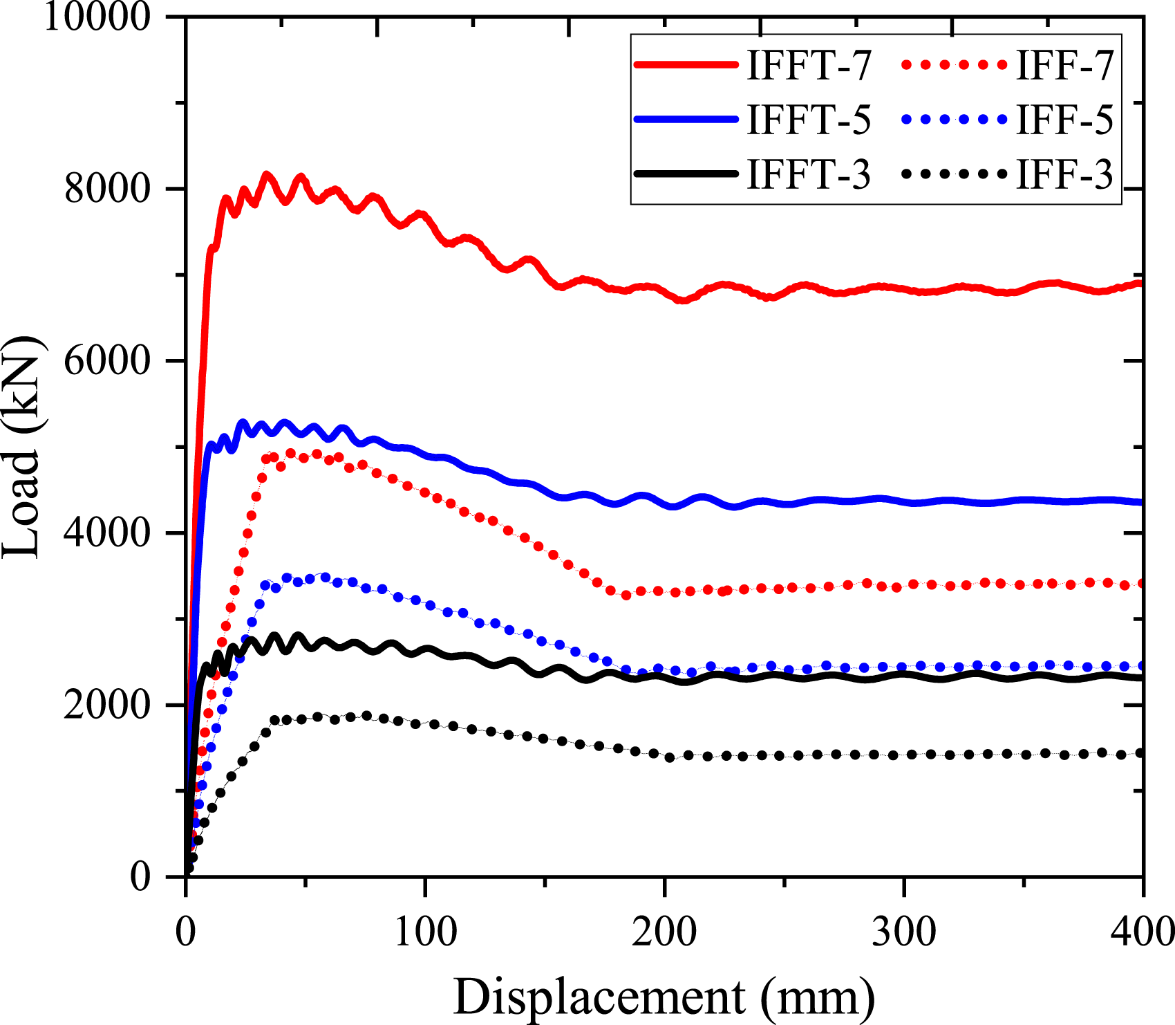
Thus, the infilled frame structures with the tie columns showed a strength increase and a noticeable increase in the stiffness. Similarly, the proposed model produces a versatile and computationally efficient tool for the design and evaluation of the resilience of a RC infilled frames having tie columns.
Conclusions
High fidelity FE models were developed in this study to examine the effect of tie columns on the progressive collapse resistance of IFF under middle CRS. To this end, the FE models of IFF were built and validated using published experimental data. Then a tie column was inserted in the same numerical model to study its effect on the progressive collapse resistance and load transfer mechanism of IFF. Subsequently, numerical models were developed to investigate the effects of number of stories, span length and longitudinal reinforcement sizes of tie column on the progressive collapse resistance of IFFT. Finally, macro-models are proposed for IFFT and validated so that macro-models can be further used for overall analysis for structures having infills and tie columns. The main conclusions are given as: 1) The load transfer path of both IFF and IFFT is truss mechanism, but the presence of tie columns changes the load transfer mechanism from a single diagonal strut to multiple diagonal struts in each infill wall surrounded by framed members. Tie columns function as additional ties and more CMU in wall panels are mobilized in compression as struts. Moreover, the inclined angles of struts are increased in each sub-panel to improve the vertical components of struts in resisting gravity load. Consequently, in this study the tie columns improve both initial stiffness (about 19%) and progressive collapse resistance of structures (about 26%). 2) With increasing the number of stories, the additional contribution of tie columns on structural resistance against progressive collapse gradually increases. The beneficial effect of tie columns on improving progressive collapse resistance is more significant in the RC infilled frames with longer span. As masonry struts dominate failure modes, further enlarging longitudinal reinforcement ratio in tie columns larger than 0.24% is not efficient. For example, increasing reinforcement ratio by 300% only improves structural capacity by 24.1%. 3) Macro-based models are proposed for IFFT, in which each sub-panel of the infill wall surrounded by RC framed members and tie columns are represented by diagonal struts and tie columns, beams and columns are modeled by fiber-based beam elements. The method to determine the width and the material properties of diagonal struts is referred to Di Trapani et al.’s work (2018). Such macro-model is capable of modeling the nonlinear behavior of IFFT with high computational efficiency compared with high-fidelity numerical modeling schemes.
This study only applies to the IFF having one tie column in the middle of each infill wall panel. Dependent on the length of each infill wall panel, more tie columns could be used, which requires further investigation. Moreover, the experiments on the IFF having tie columns under CRS should be conducted to endure that all possible failure modes can be identified by numerical analyses.
Footnotes
Declaration of conflicting interests
The author(s) declared no potential conflicts of interest with respect to the research, authorship, and/or publication of this article.
Funding
The author(s) disclosed receipt of the following financial support for the research, authorship, and/or publication of this article: This work was supported by the National Natural Science Foundation of China (No. 51978246); Fundamental Research Funds for the Central Universities (No. 2242022R10073).