
Abstract
This study examines the cyclic shear-slip performance of a novel prefabricated composite shear stud (PCSS) connector designed for accelerated bridge construction (ABC) of composite structures. An in-depth experimental procedure is employed involving the design and fabrication of four push-out specimens with two different stud configurations. The specimens are then tested under both monotonic and cyclic-to-monotonic loading protocols. Upon completion of the testing phase, a meticulous inspection of the fractography is conducted to delineate and qualify the failure mode of the PCSS connectors. Simultaneously, a comprehensive shear-slip curve is derived from the measured data, enabling a detailed analysis over the mechanical performance. Furthermore, the study calculates a series of deformation-associated indicators from the shear-slip curve, effectively quantifying the ductility, recoverability, and capacity of the PCSS. The test results accentuate a well-deformed and ductile failure mode of the tested PCSS specimens, marked by the stud fracture and crushing of surrounding concrete. This could be attributed to the constraint of vertical plates of the PCSS on the concrete, which improves the capacity and recoverability of the PCSS. Whereas, the performance of the PCSS is also notably influenced by the group nail effect, for which the ductility and per-stud capacity degrade with the increase in the number of studs. Especially, the PCSS specimen exhibits full elastic-to-plastic hysteresis loops under cyclic loads, together with the satisfied ductility, implying an excellent potential of the PCSS to dissipate energy under impact loads. In addition, the PCSS displays a robust stiffness across different cyclic loading blocks. Hence, satisfactory post-damage ductility has still been observed in the PCSS under the monotonic loading after the cyclic loading. In conclusion, this work elucidates the superiority of the PCSS in terms of capacity, ductility, and recoverability, providing a promising basis for their application in the accelerated construction of composite bridges.
Keywords
Introduction
Research background
Steel-concrete composite bridges, which fully exploits the material advantages of both high-strength steel and concrete, are widely used in medium-to-large span bridge projects due to their superior performance (Johnson and Wang, 2018). However, the application of composite bridges also poses technical challenges to the accelerated bridge construction (ABC), which is a pressing need for both bridge owners and contractors, especially in urban bridge projects (Hällmark et al., 2012). The ABC generally comprises two essential components, namely, the industrialized fabrication and installation (Khan, 2014). Since steel members are naturally prefabricated, precast concretes are employed in composite bridges erected with ABC. Therefore, cast-in-situ concrete is often required to connect the steel and concrete via shear connectors, as illustrated in Figure 1(a). Fabrication of composite bridges: (a) Conventional studs with cast-in-situ concrete; (b) Prefabricated composite shear studs (PCSS) with fully precast concrete.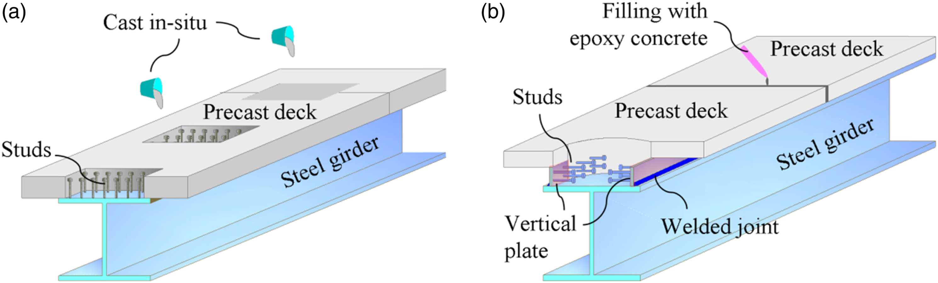
The cast-in-situ work not only causes a potential delay in construction, but also entails difficulties in maintaining the concrete quality at the same level as the in-shop pre-casting (Huang et al., 2019a; Nijgh et al., 2019). More importantly, a series of mechanical issues (e.g., cracking) will arise between the precast and cast-in-situ concrete due to their inconsistent shrinkage and creep caused by aging difference (Huang et al., 2019b; Meng and Yang, 2012). Therefore, an innovative prefabricated composite shear stud (PCSS) connector has been developed to eliminate the cast-in-situ work (Zhou, 2012, 2014), as depicted in Figure 1b. The PCSS consists of two vertical steel plate welded with a list of horizontal shear studs. The studded side of the PCSS is leveraged as the form during the pre-casting of concrete decks, with the studs buried. When installed on-site, the composite deck will be connected to the steel girder via welded joints between the girder flange and vertical plates of the PCSS.
State-of-the art overview
As the shear connector is the key component in transferring loads between the concrete and steel in composite bridges, numerous research efforts have been devoted to its mechanical behaviour under either monotonic or cyclic loads (Classen and Hegger, 2017; Kopp et al., 2018). Rather than full-scale tests that entail efforts and budgets, push-out tests (Xu and Liu, 2019) are generally employed as efficacious method to elucidate the fundamental shear-slip behaviour of shear connectors, as suggested by EN 1994-1-1 (2005). Civjan and Singh (2003) conducted push-out tests to examine the behaviour of shear studs, including both monotonic and cyclic loading. The test comprised 10 push-out specimens and 10 directly loaded bare studs. The result showed a significant reduction in the shear capacity of studs under cyclic loads compared to that under monotonic loads, i.e., about 40%. Xu et al. (2012) performed push-out tests and finite element (FE) simulations to investigate the behaviour of group studs under monotonic and cyclic loading. The results revealed that the shear stiffness and capacity of group studs decreased by 35% and 10% under the two loading protocols, respectively, relative to the uniformly distributed studs, which is known as the group nail effect (Chen et al., 2023). Further studies were carried out via the FE analysis considering the influence of concrete strength and stud size (Xu and Sugiura, 2013). The result indicated that the shear stiffness and strength of the stud decrease with the concrete strength and ratio of stud height to diameter. Moreover, the FE analysis suggested that the failure is mainly caused by the fracture of studs and crushing of the nearby concrete. He (2020) performed the push-out test and FE analysis to explore the static behaviour of group studs in hybrid fibre reinforced concretes consisting of steel fibre and polypropylene fibre. The result indicated that the capacity of the specimen slightly increases with the proportion of steel fibre, while its ductility increases with the proportion of polypropylene fibre. Zhai et al. (2018) carried out a series of push-out tests to examine the shear-slip behaviour of studs under both monotonic and cyclic loads. The test data demonstrated a remarkable reduction in ultimate capacity and slip in the specimens subjected to cyclic loads compared to those exposed to the monotonic load, which is 26.5% - 58.3% in the capacity and 56.2%–81.0% in the slip. Furthermore, the specimen exhibited a brittle failure under cyclic loads, which contrasts with the ductile failure under monotonic load. Suzuki and Kimura (2019) proposed a novel type of component model to test the cyclic behaviour of composite beams using shear studs, in which the negative moment and corresponding tensile stress are considered. The test data showed that the ultimate shear strength under tensile stress was 27%–49% of the value under compressive stress. Consequently, the ultimate shear capacity degraded when the concrete was subjected to cyclic loads.
At the same time, considerable research efforts can be also observed on various types of innovative shear connectors. Ataei et al. (2019) assessed the cyclic behaviour of bolted shear connectors via the push-out tests. A total of 12 specimens were tested, including nine under cyclic loads and three under monotonic loads. Except for one specimen that failed with concrete damage under cyclic loads, the failure in all the remaining 11 specimens was caused by the shear fracture of bolts. Moreover, it was also revealed that the capacity and ductility increase with the strength and size of the bolts. Deng et al. (2019) compared the behaviour of the angle connector, T-PBL and a novel channel connector via the push-out tests under monotonic and cyclic loads. A total of 12 specimens were tested, and the test data indicated an enhanced capacity of the proposed novel channel connector under both monotonic and cyclic loads. Furthermore, the channel connector was also proved to be robust at the energy dissipation and stiffness during cyclic loads. Zhuang et al. (2018) conducted a series of push-out tests and refined FE analysis on the monotonic and cyclic behaviour of the rubber-sleeved stud (RSS) connector, which is proposed to reduce the stress concentration in the vicinity of stud roots. The failure was caused by the stud fracture in all the specimens under both monotonic and cyclic loads. In addition, the RSS was proved to have a comparable capacity to the traditional stud, while its stiffness was reduced to 36.5% of the value in traditional studs. Following the standard test procedure suggested in Annex B.2 of EN 1994-1-1 (2005), similar configurations of push-out specimens have been used in the above works, with minor adjustments in thickness and width to accommodate the variation in shear connectors. Regarding the novel PCSS, Gao et al. (2021) performed experimental and numerical efforts to examine the shear-slip behaviour of the PCSS under the monotonic load. The result indicated that the ultimate capacity in the PCSS connector is 39.1% - 67.3% higher than that in the traditional stud connectors. Moreover, the high-resolution FE simulation showed additional confinement on the concrete near studs by the vertical steel plate, resulting in an improvement in both the capacity and ductility of the connector.
Existing research gaps
The static shear-slip behaviour of PCSS connectors has been investigated and validated under monotonic loads in previous work (Gao et al., 2021). Moreover, a full-scale experiment of the composite beam using PCSS connectors has verified the feasibility of PCSS in composite bridges (Wang et al., 2016). Meanwhile, composite bridges are generally subjected to cyclic impacts and extreme events, such as overloading, earthquake, collision, etc. Therefore, the cyclic shear-slip behaviour of connectors is a key factor in determining the structural integrity. Therefore, apart from the existing works on the feasibility and static behaviour of the PCSS, there is still a strong need for further insights into its mechanical performance under cyclic loading, which is vital for bridges exposed to dynamic loading.
Aim and scope
The present work devotes to examine the cyclic shear-slip behaviour of the novel PCSS connector, which constitutes a vital step in a succession of endeavours to furnish fundamental data support for further site applications. A series of push-out tests have been performed using a total of four specimens and with two loading protocols, namely, monotonic loading and cyclic-to-monotonic loading. The work is presented in the following manner: in Part 2, the programme of push-out tests is described in detail, including the specimens design, test set-up, instrument and loading protocol; in Part 3, the test results are presented and discussed, including the failure mode and load-slip curves; in Part 4, further quantitative analysis is carried out on the test data to provide deeper insights into the cyclic and post-cyclic performance of the PCSS; in Part 5, the main conclusions are drawn from the work, and further recommendations are given. In general, this study highlights the superior performance of the PCSS in capacity, ductility and recoverability, and offers a useful guideline for the future application of PCSS connectors in accelerating the construction of composite bridges.
Test programme
Design of specimens
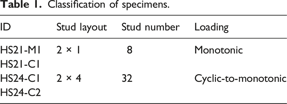
In the study, a total of four push-out specimens have been fabricated, including two specimens with one-row studs (coded as HS21 for short) and two specimens with group studs (coded as HS24 for short), as shown in Figure 2. Apart from the layout of the studs, the specimens are kept the same in both the material and configuration. The specimen consists of a steel box and two deck plates, connected via the PCSS. The deck plate is in a T-shaped section, of which the thickness increases from 150 mm at the edge to 250 mm at the rib. Meanwhile, the steel box is made up of four 8 mm-thick steel plates. The PCSS consists of two vertical steel plates in 8 mm and a series of 50 mm-high steel studs. It is worth noting that the height is determined after the clearance between two vertical plates. In order to keep a reasonable flexibility of studs Dönmez (2021), the stud diameter is determined as 10 mm, corresponding to a height-to-diameter ratio of five and consistent with the value in the previous static test (Gao et al., 2021). The vertical plate and stud are joined by full penetration welding. Besides, the vertical plate and the top flange are designed to connect via 75% partial joint penetration welding (PJP) from outside. Layout of specimens: (a) Single stud (2x1); (b) Group studs (2x4).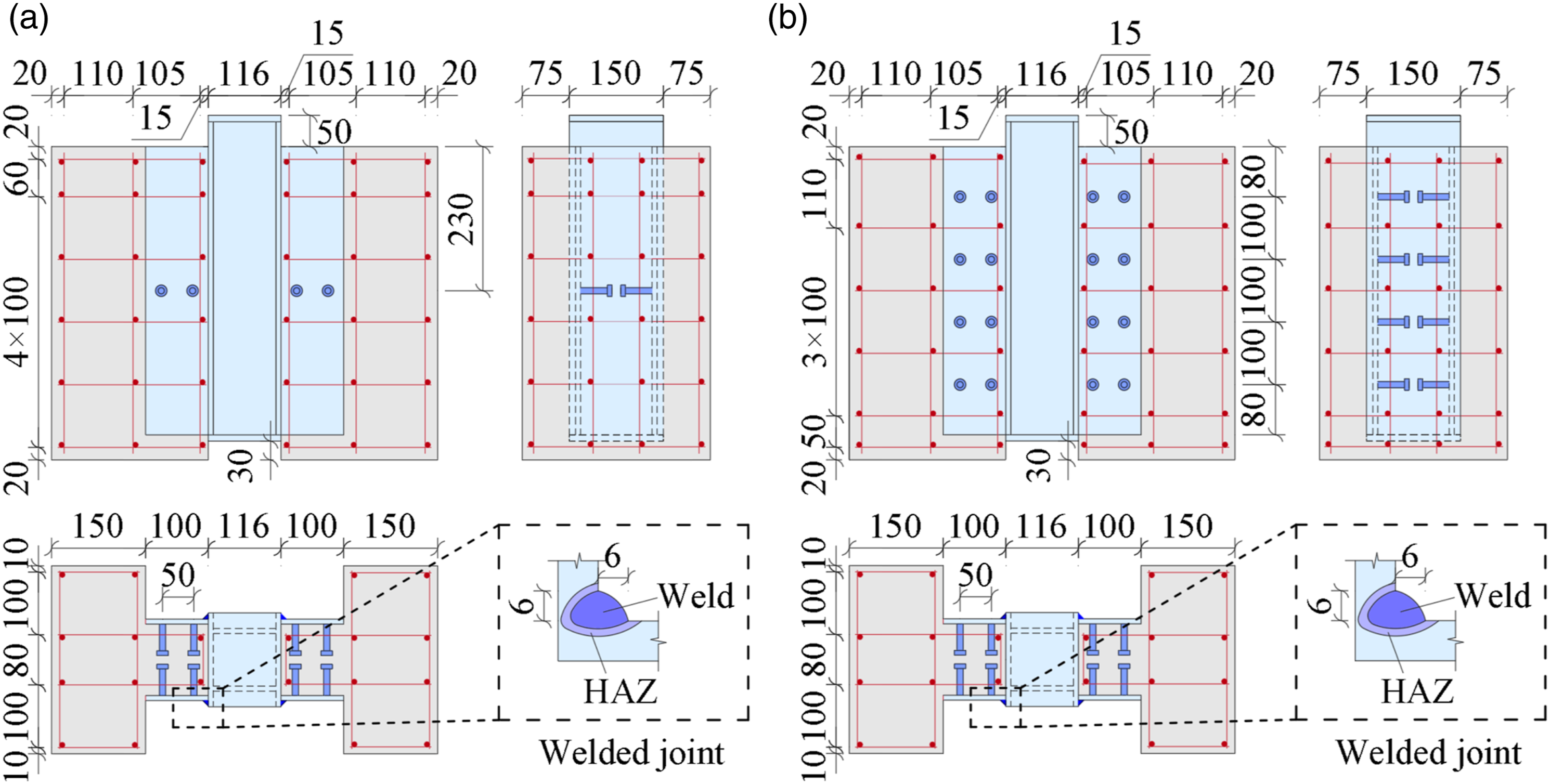
Classification of specimens.
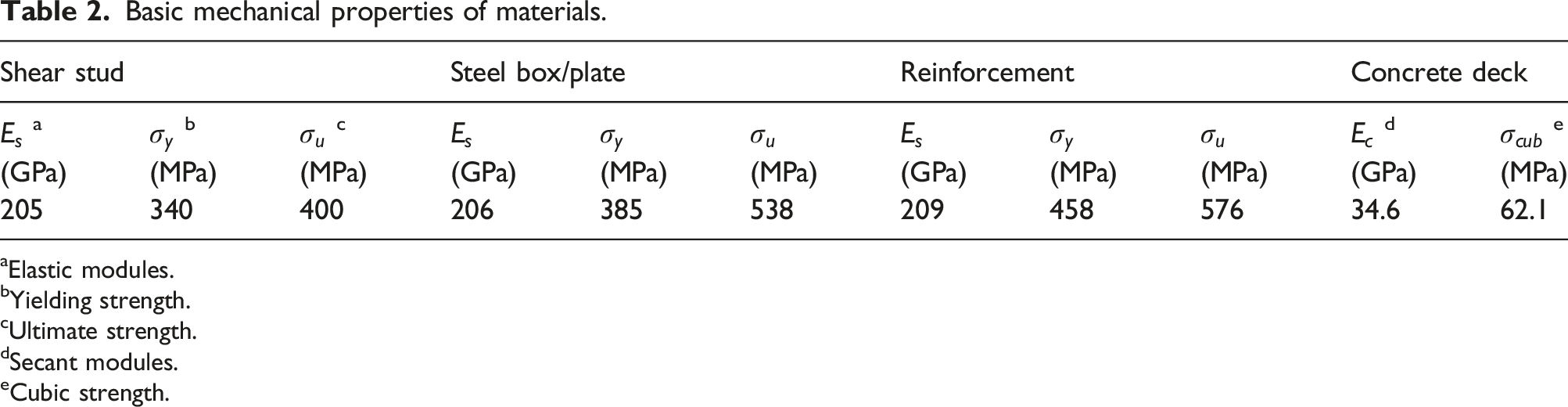
Uniaxial tensile tests are performed on the stud sample of ML15 and the steel coupon of Q345 B after the standard procedure suggested in GB/T 228.1–2021, 2021, as shown in Figure 3(a) and (b). The stud sample has the same diameter of 8 mm as the one used in the push-out specimen, but its length is set to 200 mm to ensure adequate clearance between two clamps. The steel coupon has a thickness of 8 mm, consistent with the push-out specimen, and a gauge length and width of 15 mm and 60 mm, respectively. The concrete material is evaluated by the uniaxial compression test of prismatic specimens according to the standard procedure suggested in GB/T 50081-2019 (2019), similar to EN 1992-1-1 (2004), as shown in Figure 3(c). The prismatic specimen has a width and length of 150 mm, and a height of 300 mm. Table 2 lists the major test results. It is worth noting that the cubic strength is derived from the prismatic strength after EN 1992-1-1 (2004). Material test (courtesy of Dr LI Chengjun): (a) ML15 stud; (b) Q345 B steel; (c) C60 concrete. Basic mechanical properties of materials. aElastic modules. bYielding strength. cUltimate strength. dSecant modules. eCubic strength.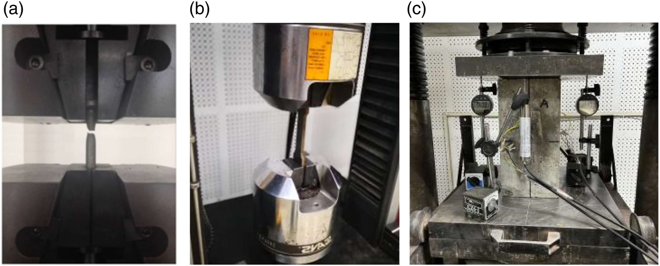
The specimen is fabricated through four major steps, as respectively shown by Figures 4(a) to (d). The studs are at first welded to the vertical plate, as shown in Figure 4(a), forming the PCSS. Before casting the concrete, the reinforcements are bonded to the framework and placed between the concrete forms, as shown in Figure 4(b). As aforementioned, the studded side of the PCSS also serves as the concrete form during casting, with the studs embedded in the concrete. The precast concrete undergoes steam curing for 28 days in the chamber to enhance its mechanical performance and eliminate the effect of creep and shrinkage. After that, the concrete deck is joined with the steel box by welding the two vertical plates of the PCSS to the flange of the box, as shown in Figure 4(c). The 75% PJP welded joint is finished with a semi-auto welder from the outside. Figure 4(d) shows the specimen in its final state. Fabrication procedures of the specimen: (a) PCSS formation; (b) Reinforcement binding and concrete casting; (c) Specimen fit-up by welding; (d) photography of complete specimen (courtesy of Dr LI Chengjun).
Test set-up and instrument
The set-up of push-out tests is illustrated in Figure 5. The electro-hydraulic tester YAW10000 F (POPWIL Inc (2023)) is employed for loading, which has a maximum capacity of 10,000 kN. The actuator is imposed to an extraordinarily thick end plate on the top of the steel box to distribute the applied load. Moreover, the bottom end of the concrete deck is placed on the supporting base without any extra constraints. Notably, the fine-grained sand is placed between the concrete and supporting base, to reduce the lateral constraint on the concrete. Simultaneously, electrical dial gauges (with a minimum resolution of 1 μm) are installed near studs to measure the slip between the concrete deck and steel box. Set-up and instrument: (a) Schematic view; (b) Photography (courtesy of Dr LI Chengjun).
Loading protocol
As evidenced in current works (Xu et al., 2012; Xue et al., 2012; Luo, 2008; Zou et al., 2022), the ultimate state of shear stud-based connectors is primarily governed by the capacity of studs, with a minor impact by the surrounding concrete. Meanwhile, a group nails effect occurs in the specimen containing multiple studs, reducing the total capacity. Due to the multitude of influential factors, the group nail effect is difficult to determine before the test (Xiang and Guo, 2017). Therefore, the group nails effect is disregarded in designing the loading protocol. Accordingly, the target load of the push-out specimen at the ultimate state is estimated by summing up the capacity of each stud (GB 50917-2013, 2013), as illustrated in equation (1).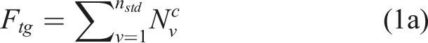

Two loading protocols are designed based on the target load The loading protocol: (a) Monotonic; (b) Cyclic-to-monotonic.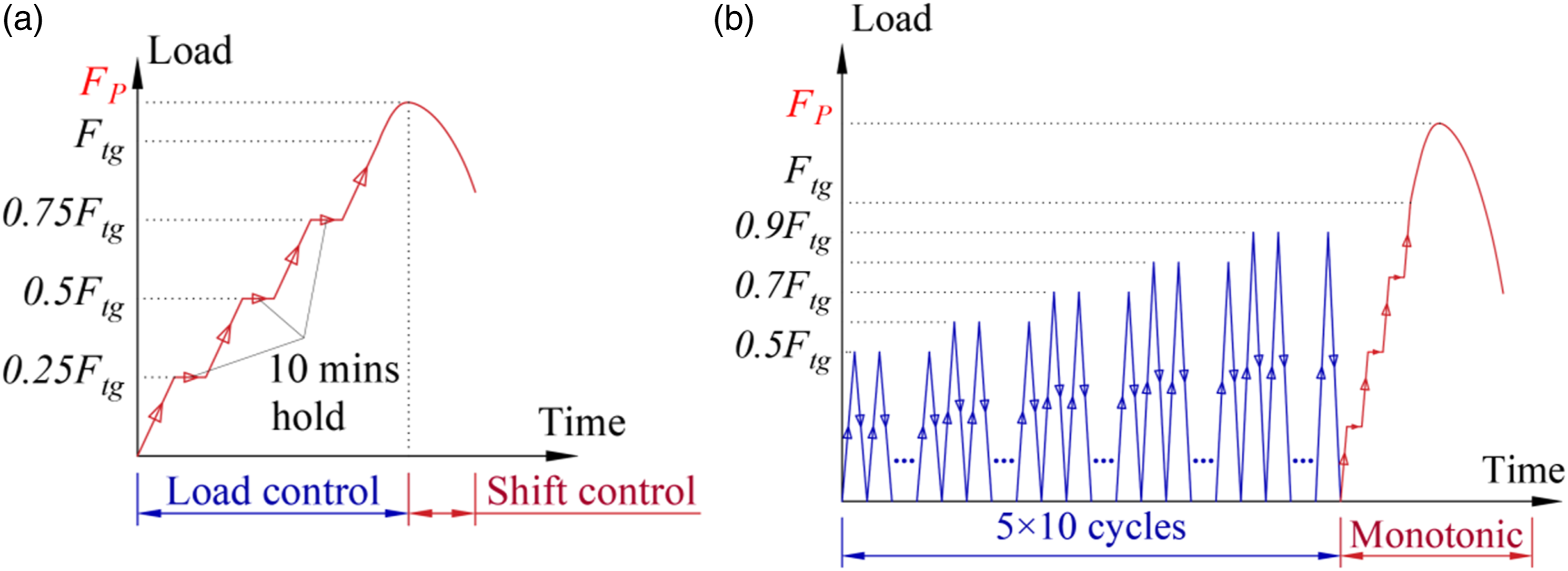
Test result and discussion
Failure mode
After the loading test, the specimens are cut into macro-sections to inspect the fractography near broken studs. Figure 7(a) and (b) show the post-failure fractography of the HS21-M1 (by monotonic loading) and HS21-C1 (by cyclic-to-monotonic loading), respectively. In both specimens, the stud breaks at the transition section between the head and shank, along with a concrete plastic damage (CPD) zone. The fracture surface of the HS21-M1 remains almost perfectly circular, as shown in Figure 7(a), suggesting a limited crushing between the stud and concrete. Upon a closer look, a typical shear slip can be observed on the fracture surface of the HS21-M1, indicating the ductile failure with the well-developed deformation of the stud. Unlike the HS21-M1, the fracture surface is highly skewed in the HS21-C1, as shown in Figure 7(b), which confirms an increased crushing between the stud and concrete. More importantly, the HS21-C1 shows clear marks of crack growth in addition to the shear slip on the fracture surface. Clearly, the damage in studs accumulates with loading cycles. As a result, the capacity of the HS21-C1 degrades significantly compared with the HS21-M1, which will also be discussed in detail in the following Section “Deformation performance under cyclic loads”. Simultaneously, the HS21-C1 also exhibits an extended CPD zone due to the cyclic loading. As shown in Figure 7, the length of the CPD zone increases from 3.0 mm in the HS21-M1 to 4.3 mm in the HS21-C1, i.e., an increase by 43.3%. Consequently, a much higher slip can be expected at the ultimate state, which will also be investigated in detail in the following part. Furthermore, a few tiny cracks can be detected in the CPD zone in the HS21-C1, illustrating the aggravated damage in the concrete by the cyclic loading. Failure mode of HS21 specimens: (a) Monotonic loading; (b) Cyclic-to-monotonic loading.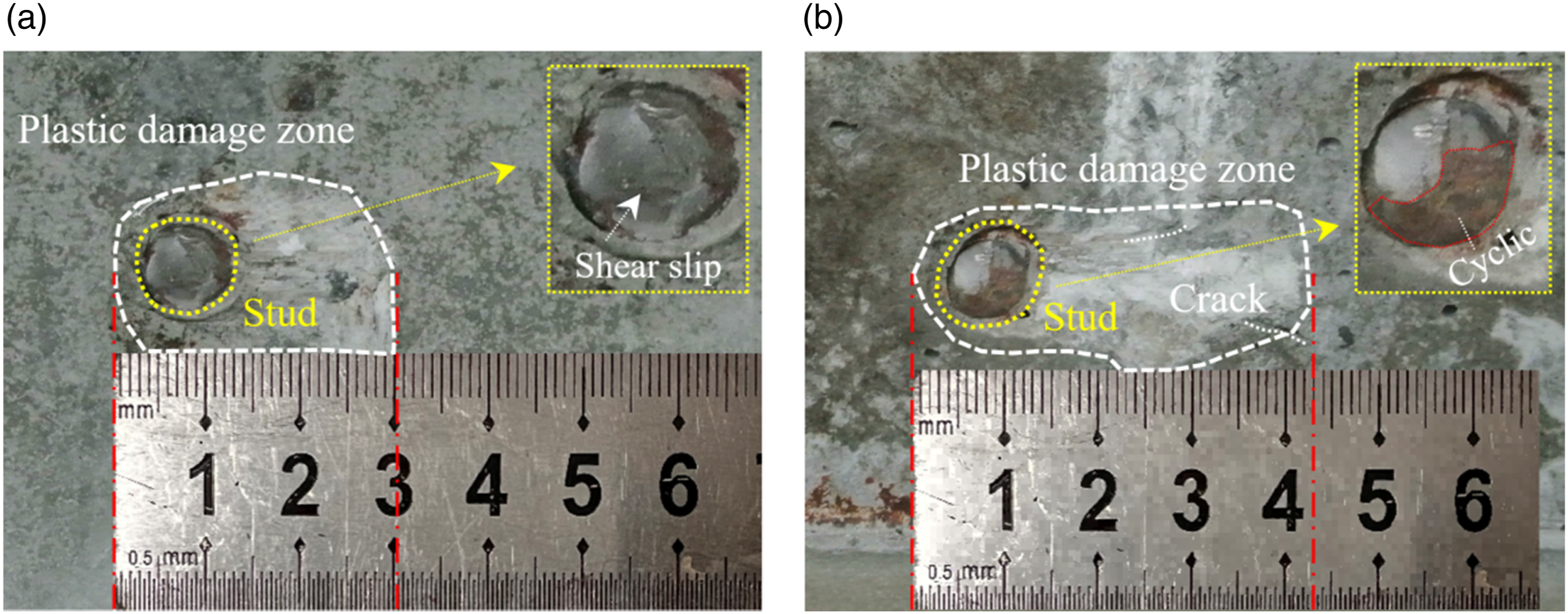
The specimens HS24-C1 and -C2 are also examined using the same method, as shown in Figure 8(a) and (b), respectively. Compared with the HS21-C1 that has only one row of studs, the fracture surface in the HS24 specimens (with four rows of studs) shows a moderate skewness between the HS21-M1 and -C1. Thus, the crushing between the concrete and stud decreases with the increase in the number of studs. Simultaneously, the proportion of the crack growth zone in the stud is also reduced in the HS24 specimens, reflecting less damage accumulation. Furthermore, an extended CPD zone is observed (i.e., 5.6 mm and 4.9 mm in the HS24-C1 and -C2, respectively), along with more tiny cracks detected. This can be attributed to two major factors induced by more studs, namely, the insufficient deformation of studs, and the increased proportion of capacity undertaken by the studs. Failure mode of HS24 specimens by cyclic-to-monotonic loading: (a) HS24-C1; (b) HS24-C2.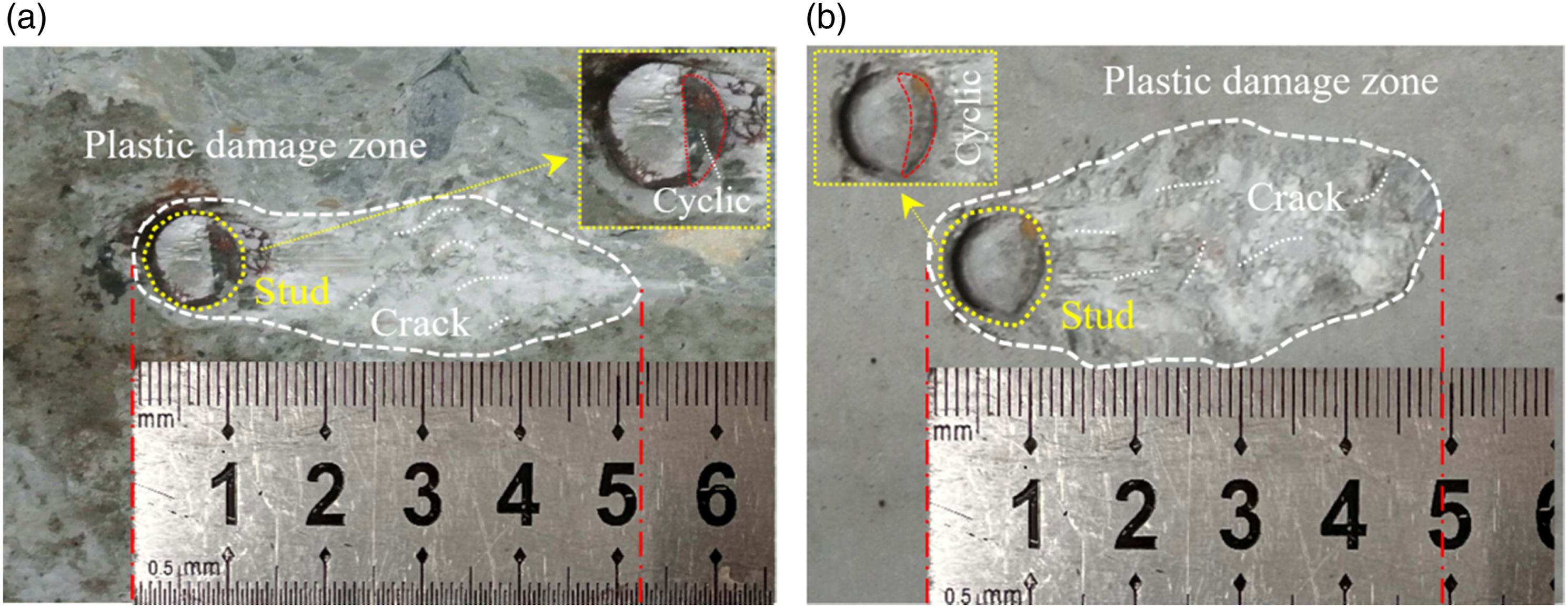
Load-Slip curve
As mentioned earlier, the slip between the concrete deck and the steel member is measured by dial gauges against the applied load. Figure 9(a) to (d) show the load-slip curves obtained from the test. For the specimen HS21-M1 (which has two columns × 1 row of studs and is subjected to monotonic loading), a significant deformation is observed (see Figure 9(a)). The curve exhibits a negligible linear segment until the shear force reaches 100 kN, which corresponds to 19% of the peak load. Beyond this point, the curve ascends to an inflection point at 410 kN, followed by a moderately rising segment until a peak force of 521 kN is achieved at a slip of 1.06 mm. As the load gradually declines from 521 kN to 437 kN, fine cracks emerge in the concrete around the shear studs, indicating the progressive failure of the concrete. When the load drops below 437 kN, the concrete cracks become more pronounced, and a conspicuous gap is formed between the deck and the steel box. When the load reaches approximately 329 kN, a loud snapping sound is audible, signifying the fracture of studs. Subsequently, cracks in the concrete propagate swiftly and start to coalesce. Consequently, partial concrete crushing and even spalling are observed, corresponding to the second inflection point on the curve. Load-slip curve measured from tests: (a) HS21-M1; (b) HS21-C1; (c) HS24-C1; (d) HS24-C2.
Figure 9(b) to (d) depict the shear-slip curve obtained in the three PCSS specimens under the cyclic-to-monotonic loading. In general, the curve shifts towards the right with the number of loading cycles, indicating the gradual damage accumulation in the specimen. Meanwhile, the slope of curves also declines with loading cycles, from which degradation in stiffness can be inferred. Moreover, as indicated by the increasing width of hysteresis loops, the yielding portion of steel studs also expands with cycles. It is noteworthy that the hysteresis loop maintains a plump shape regardless of cycles, which confirms the robustness of PCSS connectors in energy-dissipation under extreme loads. The state change of the three specimens during cyclic loading is illustrated by connecting the peak values of each cycle at different load levels with dashed lines in Figure 9(b). For the specimen HS21-C1 with one row of studs, the dashed line exhibits a decreasing slope, which is contradicted to the proportional increase of load range in each cycle. This indicates a notable reduction of secant stiffness with the number of loading cycles. For the specimens HS24-C1 and -C2 with four rows of studs, the dashed line shows a less pronounced curvature, suggesting a smaller loss of stiffness due to the mitigated cyclic damage in studs, as discussed in Section “Failure mode”. The above noted stiffness degradation will be further discussed and quantified using deformation-associated indicators in Section “Stiffness degradation”.
The post-cyclic behaviour of the specimens can be also evaluated by comparing HS21-M1 and HS21-C1. The peak capacity of HS21-C1 is reduced by 12.7% from 521 kN to 452 kN due to the accumulated damage by cyclic loads. Similar to the HS21-M1, visible concrete cracking occurs as the applied load decrease from the peak of 452 kN to 431 kN, accompanied by the separation between the concrete deck and steel box. The load continues to decrease with the increasing slip until a fracture sound is heard at 342 kN, indicating the progressive failure of the specimen. The specimens HS24-C1 and C2, which have two rows of studs, exhibit a similar post-peak behaviour under cyclic loading. It is noteworthy that the ultimate capacity does not increase linearly with the number of studs. For instance, the ultimate capacities of HS24-C1 and C2 are respectively 1592 kN and 1533 kN, which are only 3.5 and 3.4 times the capacity of HS21-C1. This can be explained by the group nails effect discussed in Section “Loading protocol”. Moreover, both the specimen exhibits a good ductility after cyclic loading, which will be evaluated along with the post-cyclic capacity by quantitative indicators in Section “Post-cyclic ductility and capacity”.
Deformation performance under cyclic loads
Selection of deformation-Associated indicators
A quantitative investigation is further carried out on the load-slip curve of the three specimens (see Figure 9(b) to (d)) under the cyclic-to-monotonic loading. Regarding the cyclic stage, the load-slip curve is marked by four key indicators, as illustrated in Figure 10(a). The four key indicators are derived from each loading cycle (labelled as i) under various load ranges (denoted as Definition of key deformation-associated indicators from load-slip curves: (a) Cyclic stage; (b) Monotonic stage.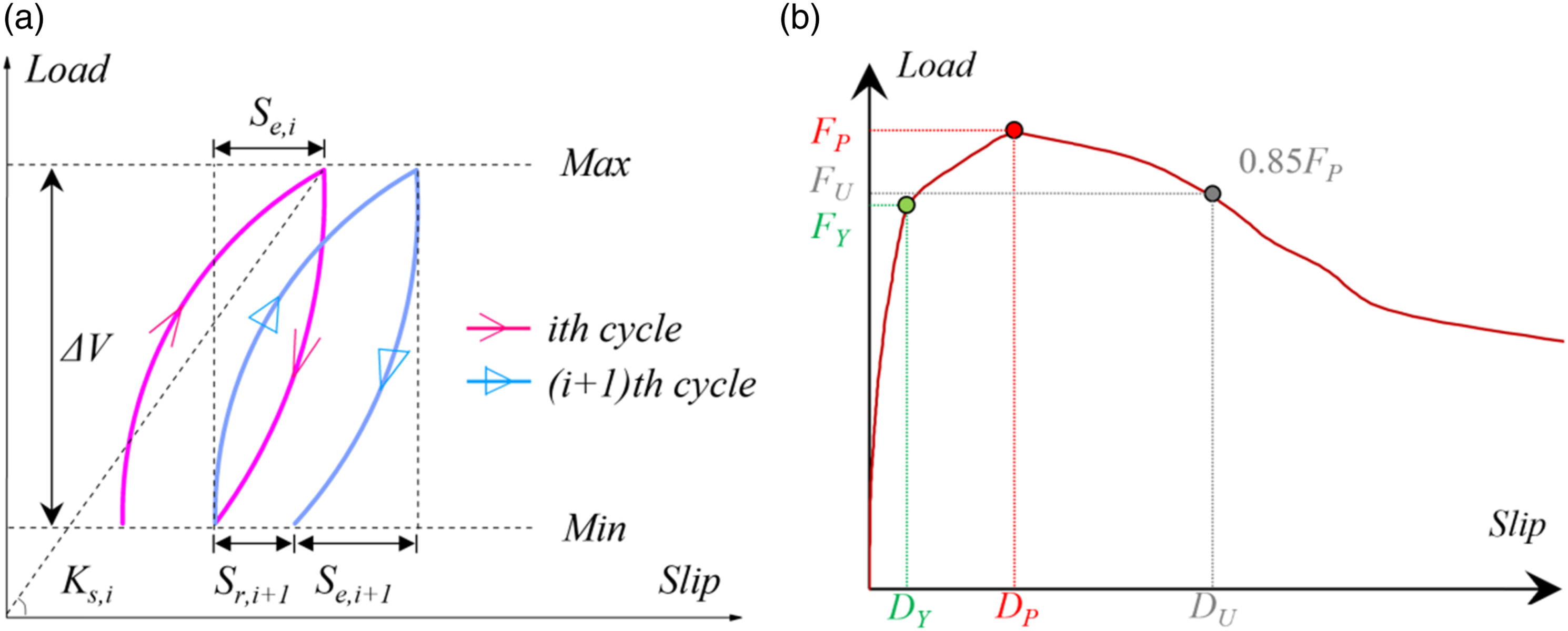
On this basis, two ductility coefficients (DC) can be derived, as presented by equations 2(a) and (b),
Elastic slip and residual slip
Figure 11(a) to (c) show the evolution of elastic slip Evolution of elastic slip with cycles: (a) HS21-C1; (b) HS24-C1; (c) HS24-C2.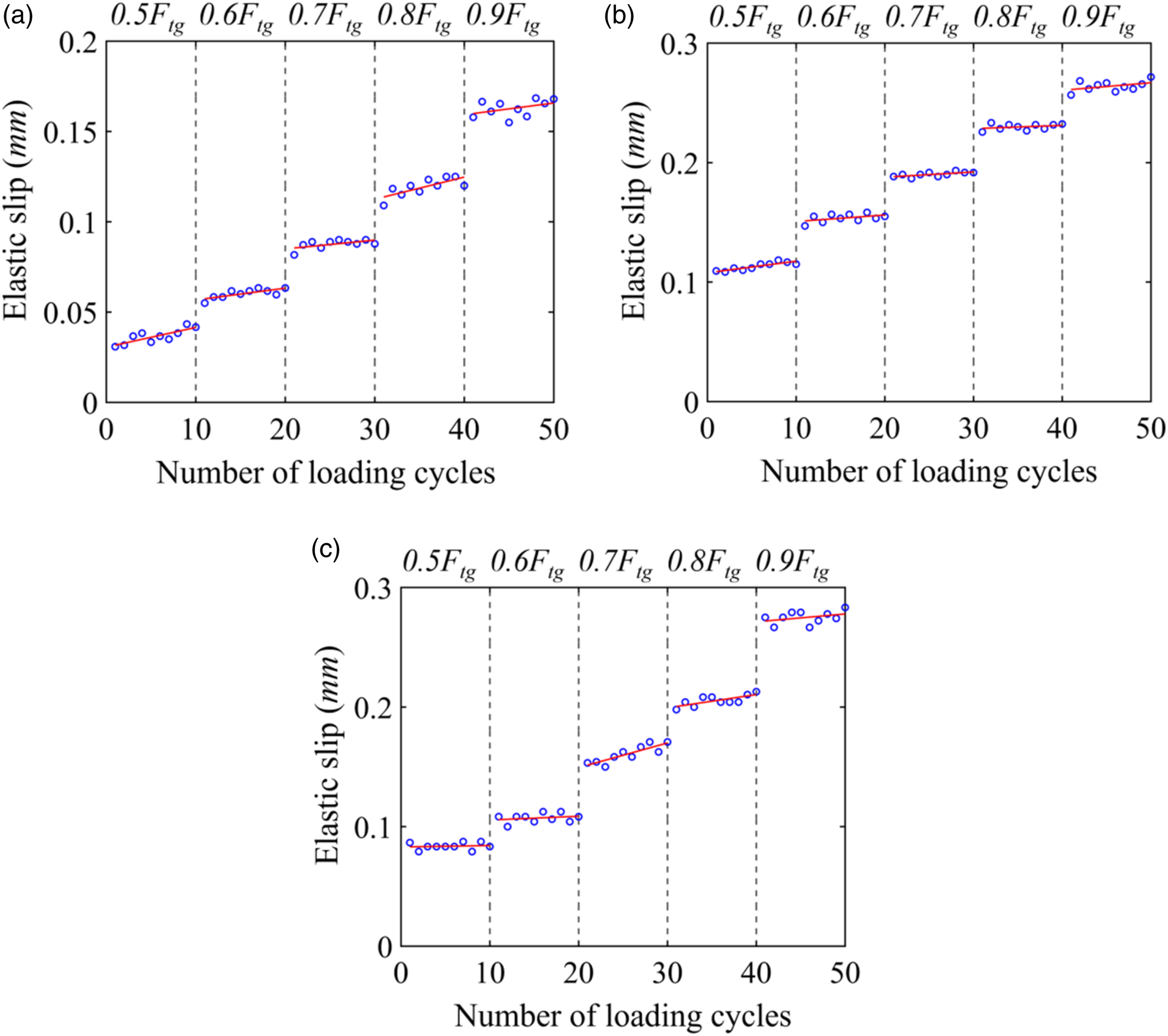
Further comparison can be made between Figure 11(a) to (c) to investigate the influence of the number of studs. The specimen HS21-C1 (with one row of studs) exhibits a lower elastic slip than the specimens HS24-C1 and C2, which have four rows of studs. The ratio of HS21-C1 to HS24-C1/2 decreases with the number of loading cycles, from 3.5/3.0 at the first cycle to 1.5/1.7 at the end of 50 cycles. This can be attributed to the additional stiffness provided by the concrete constraint and the associated damage accumulation. According to the previous work (Gao et al., 2021), the vertical steel plate in the PCSS enhances the stiffness of the specimen due to the interaction and friction between the steel and concrete interfaces. The study also indicates a rapid damage evolution in the concrete before the yielding load, along with moderate damage in studs. This is consistent with the test observation of fine cracks in the near-stud concrete in Section “Test result and discussion”. As previously shown by Figure 9(b) to (d), the supplementary stiffness from the concrete deteriorates at an increasing rate with loading cycles, leading to a faster increase in the elastic slip in the specimen HS21-C1 with one row of studs. Figure 12 presents the residual slip Evolution of residual slip with loading cycles.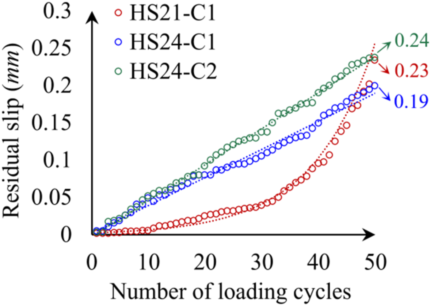
Stiffness degradation
Figure 13 depicts the change in stiffness as a function of the number of loading cycles. The regression curve indicates that the stiffness deteriorates logarithmic with loading cycles in all three specimens regardless of the stud layout. However, there is a noticeable difference in the initial value and the deterioration rate of stiffness between the HS21-C1 and HS24-C1/2. The HS21-C1 has a very high initial stiffness of 811 kN/mm, which is 3.9 and 3.0 times higher than the HS24-C1 and -C2, respectively. The stiffness also decreases much faster in the HS21-C1 than in the other two HS24 specimens. At the final cycle, the stiffness in the HS21-C1 drops from the initial 811kN/mm to 130 kN/mm, which is only 0.6 and 0.8 times higher than the HS24-C1 and -C2. Evolution of stiffness degradation with loading cycles.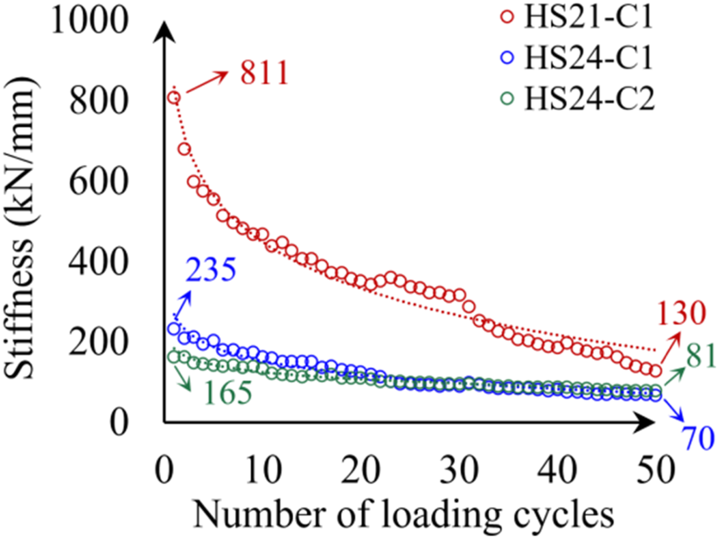
As explained in Section “Elastic slip and residual slip”, the higher initial stiffness and faster degradation can be related to the effect of constraint and friction on the steel-concrete interface, and also, the rapid damage accumulation in the concrete around studs. The result suggests that an increased number of studs could improve the recoverability and integrity of the PCSS connectors under cyclic loads. However, the number of studs should be carefully designed to balance the performance of concrete and steel due to the possible reduction in the capacity per stud by the group nail effect.
Post-Cyclic ductility and capacity
Ductility and residual capacity.
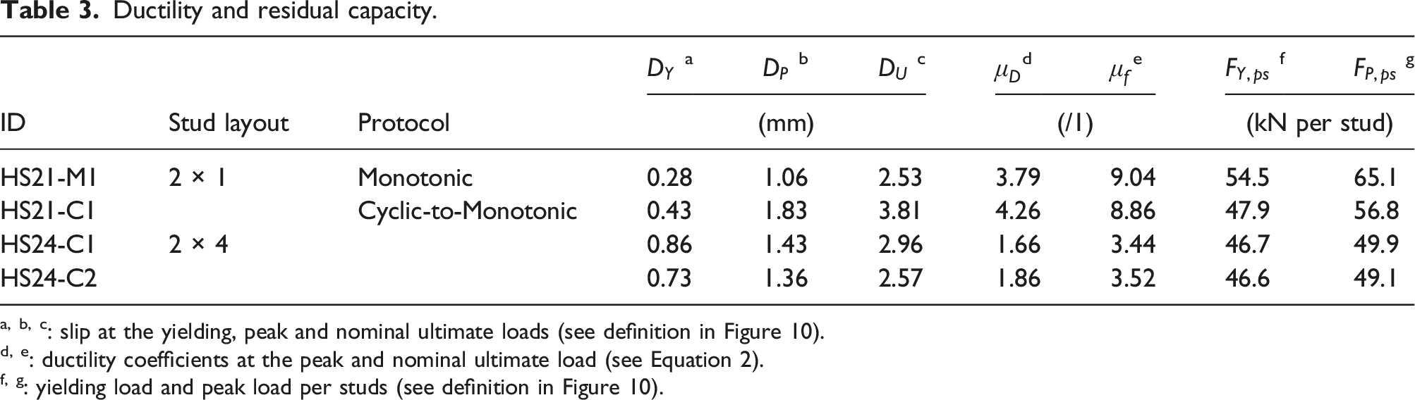
a, b, c: slip at the yielding, peak and nominal ultimate loads (see definition in Figure 10).
d, e: ductility coefficients at the peak and nominal ultimate load (see Equation 2).
f, g: yielding load and peak load per studs (see definition in Figure 10).
An interesting observation is that HS21-C1 has a slight reduction in the ductility coefficient at the nominal ultimate load, even though its slip at that load is higher than the HS21-M1. In general, the ductility of the PCSS does not deteriorate significantly after the high-level cyclic loads. However, the cyclic loading has a considerable impact on the post-cyclic capacity of the PCSS. Regarding the yielding load per stud
A further analysis can be conducted with respect to the number of studs. As the row of studs increases from one in the HS21-C1 to four in the HS24-C1/2, the ductility coefficient (DC) declines sharply. Consequently, the peak DC
The two HS24 specimens exhibit similar post-cyclic capacities, i.e., 49.9 kN and 49.1 kN, which are reduced by 12.1% and 13.6%, respectively, compared to the capacity of 56.8 kN per stud in the specimen HS21-C1. As discussed in Sections “State-of-the art overview” and “Loading protocol”, this reduction can be attributed to the group nail effect that lowers the capacity per stud due to insufficient deformation of each stud. Likewise, the ductility is also notably decreased with more studs, as discussed above. Although the total capacity of the PCSS can be improved by increasing the number of studs, the maximum capacity of each stud is not fully exploited, as reflected by the capacity per stud. Moreover, the dense layout of studs also degrades the general ductility of the PCSS. On the other hand, the recoverability and integrity are significantly enhanced with the increased number of studs, as expressed in terms of the stiffness degradation and residual slip discussed in Sections “Elastic slip and residual slip” and “Stiffness degradation”. This enhancement can be also associated with the reduced cyclic damage in studs of HS24-C1 and -C2, as observed in Figures 7 and 8. Hence, a proper design of the stud layout is highly suggested for an optimal trade-off between capacity, recoverability, integrity and ductility.
Conclusion and future recommendation
In this work, a series of comparative push-out tests have been meticulously executed to scrutinise the cyclic behaviour of an innovative Prefabricated Composite Shear Stud (PCSS) connector, designed for accelerated bridge construction (ABC) of composite structures. The test procedure incorporated two specimen types, namely, HS21 and HS24, subjected to monotonic and cyclic-to-monotonic loading protocols. The main findings are as follows: (1) From macro-section inspections, the predominant failure in all specimens stems from the ductile fracture of studs at the shank-to-head section. Compared with monotonic specimens, specimens under cyclic-to-monotonic loading display obvious cyclic damage in studs and concrete crushing. (2) The shear-slip curve underscores the robustness of the PCSS in ductility under both loading protocols. The curve indicates a yielding-to-hardening stud behaviour, full post-peak deformation, and substantial energy dissipation under extreme loads, illustrated by plump hysteresis loops. (3) The cyclic loading shows a marginal impact on the capacity and ductility of the PCSS. In the HS21 specimens, the post-cyclic shear capacity decreases by 12.7% while the ductility shows no apparent degradation. (4) Consistent with prior studies on static behaviour, this work also reveals augmented stiffness in the PCSS due to friction and constraint on the concrete-to-steel plate surface. The stiffness eliminates quickly due to the concrete crushing near studs under cyclic loads. (5) The number of studs affects the trade-off between the recoverability, integrity, ductility and post-cyclic capacity of the PCSS. A denser stud layout leads to the potential group nail effect, reducing the ductility and per-stud capacity. Thus, an optimal design of the stud deployment in the PCSS is essential in achieving balanced capacity, recoverability, and ductility.
This work presents a pioneering investigation on the cyclic behaviour analysis of the novel PCSS connectors, laying a solid foundation for their future applications in ABC. Further experimental studies with different specimen configurations are recommended, along with numerical simulations to visualise the damage evolution per cycles. Furthermore, full-scale tests of composite girders using the PCSS are strongly encouraged under cyclic loading, as a critical step towards the engineering application.
Footnotes
Author Contributions
Declaration of conflicting interests
The author(s) declared no potential conflicts of interest with respect to the research, authorship, and/or publication of this article.
Funding
The author(s) disclosed receipt of the following financial support for the research, authorship, and/or publication of this article: This work was supported by the National Natural Science Foundation of China (52278220, 51878564, 52208182, U21A20154), Sichuan Science and Technology Programme (2021JDTD0012) and Shenzhen Science and Technology Program (JCYJ20220531101010020).