
Abstract
This paper proposes an assembled X-shaped flexural steel damper. Welding is waived for the novel damper. As the kernel element of the damper, the X-shaped flexural steel plates have the advantages of ease of installation and replacement if necessary. In the analytical part, the effective height of the flexural steel plate was suggested, and then, the yield displacement, yield load and initial stiffness of the damper were derived. The proof-of-concept cyclic loading test was conducted using one reduced-scale specimen within a four-bar linkage experimental setup. The hysteretic performance indexes, including strength, stiffness and energy dissipation, were quantified. The high-fidelity finite element (FE) models were established by ABAQUS. The parametric study was further conducted based on the verified FE model. The considered parameters were the height and thickness of the steel plates. The testing results indicate that the proposed damper has plump hysteretic curve with good energy dissipation capacity and excellent ductility, although slight slip behavior can be found due to the gap caused by the assembling process. The results obtained from analytical method and numerical model are in good agreement with the experimental data. The results of parametric analysis show that the numerical results well agree with analytical predictions, indicating the numerical model can reflect the mechanical behavior of AXSFD. A benchmark frame building was selected to demonstrate the seismic control efficacy of the damper. The nonlinear time history analysis results indicate that the damper reduced both peak and residual interstory drift ratios for the protected structure.
Keywords
Introduction
Conventional seismically resistant structures withstand strong earthquakes through the plastic deformation and damage of the main members. The collapse prevention target can be achieved, but it is very difficult to repair the damaged structures (Stephen, 1997; Yamaguchi and Yamazaki, 2010). Through dissipating seismic energy and localizing plastic deformation, the installed passive dampers can effectively reduce the structural damage. The popular candidates include metallic dampers, friction dampers, viscous dampers and viscoelastic dampers. However, depending on the working mechanism, there are different problems for different dampers. The friction dampers are affected by the durability of the friction interfaces and they may require proper maintenance (Jaisee et al., 2021). Viscous dampers have the problem of liquid leakage (Zhu et al., 2020). The viscoelastic dampers are sensitive to the variation of ambient temperature and loading frequency (Chen et al., 2019, Christopoulos and Montgomery, 2013).
In contrast, the metallic dampers have stable mechanical properties and energy dissipating capability. Representative metallic dampers include steel bucking-restrained braces, shear-type steel damper, bending-type steel damper, shear-bending type steel damper and torsional steel damper. To achieve a simultaneous yielding at the cross sections over the entire height, the steel plates were fabricated into triangular and X shapes by Whittaker et al. (1991) and Tsai et al. (1993), respectively. Further efforts were devoted to improve the behavior these dampers. For example, the axial force was released by inserting a steel pin shaft between two triangular steel plates (Khoshkalam et al., 2021). Shear steel plate was combined the X-shaped steel plate to increase strength and stiffness, which was experimentally validated (Oinam and Sahoo, 2018). However, it is worth noting that the boundary ends of the steel plates are often fixed by welding technology, which tend to generate negative impact to the hysteretic behavior of the damper. For example, according to the experimental tests (Chen et al., 2022; Sahoo et al., 2015), the failure of dampers was induced by the fracture at the welding regions.
Hence, this paper proposes an assembled X-shaped flexural steel damper (AXFSD). The AXFSD consists of a group of X-shaped steel plates and is assembled by steel threaded rods. The paper firstly describes the configuration and working mechanism of the damper. After that, the effective calculation height of the X-shaped steel plates is suggested, and accordingly, the equations governing the cyclic behavior are derived. To verify the behavior of the damper, a reduced-scale specimen was fabricated and then was subjected to cyclic loading tests. Besides with observing the deformation process and failure mode in the tests, the experimental data are used to plot hysteresis curves and quantify the strength, stiffness and equivalent damping ratio. Finite element (FE) models were established in ABAQUS (2019) to conduct parametric analysis, which included the installation gap, effective height and thickness of steel plates. In particular, the accuracy of the equation for calculating the effective height of steel plates is assessed. Finally, a benchmark frame building was selected for demonstrating the seismic control efficacy of the damper.
Configuration of the damper
Figure 1 shows the configuration of the damper. The damper consists of a group of X-shaped steel plates, rigid steel blocks, steel threaded rods and nuts. In comparison with existing metallic dampers, the major difference of the proposed damper is that it is assembled by bolting connections, rather than welding technology. Hence, the problems induced by the welding process, such as the residual stress and early fracture, can be waived. Besides, the welding quality depends on the technicians. Owing to the assembling manner, the damper can be more efficiently fabricated, installed, repaired and replaced. The X-shaped steel plates are the kernel element of the damper. Both ends of the steel plate are enlarged for purposes of reducing stress and clamping end. The steel blocks and steel plates are placed alternatively and they are drilled for passing through the steel threaded rods. The bolts are fastened by turn-of-nut method, which generates friction between the steel blocks and steel plates. The mechanical behavior of the damper is mainly determined by the individual behavior of each X-shaped steel plate. Notably, if the welding quality of the traditional damper is reliable, the cyclic behaviors of the traditional and proposed damper expected to be identical to each other. Configuration of AXFSD.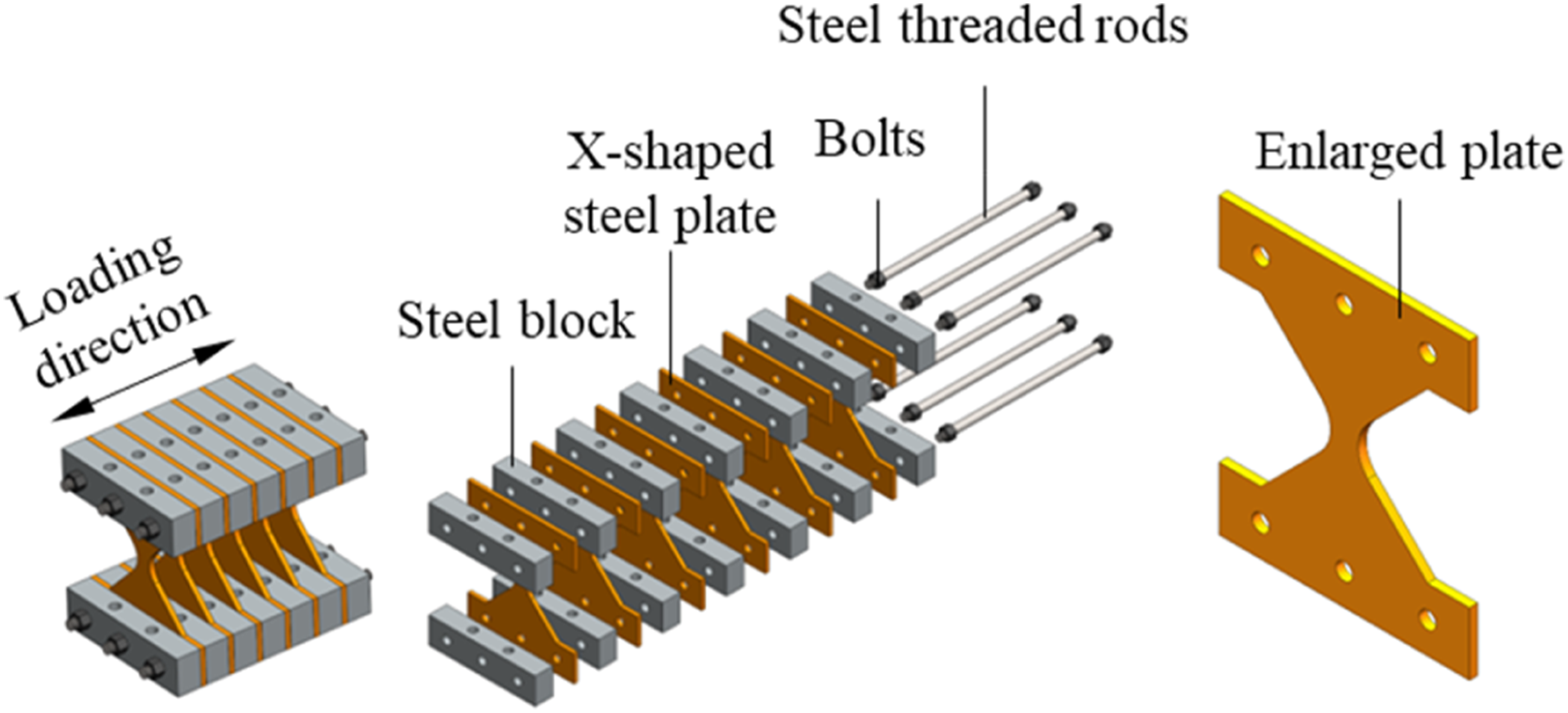
Figure 2 shows one representative installation manner of the proposed damper within a steel frame. In this figure, the top of the damper is bolted to the bottom flange of the beam and the bottom of the damper is supported by inverted V shape rigid braces. The supporting braces should be rigid and strong to avoid buckling induced instability when the damper reaches its maximum load capacity. Based on rigid floor assumption, the beam will move horizontally with the floor. Hence, the rotation of the beam is deemed very small and can be neglected. Under earthquakes, the interstory drift deforms the damper, which provides force resistance and absorbs seismic energy in return. Installation of AXFSD in a steel frame.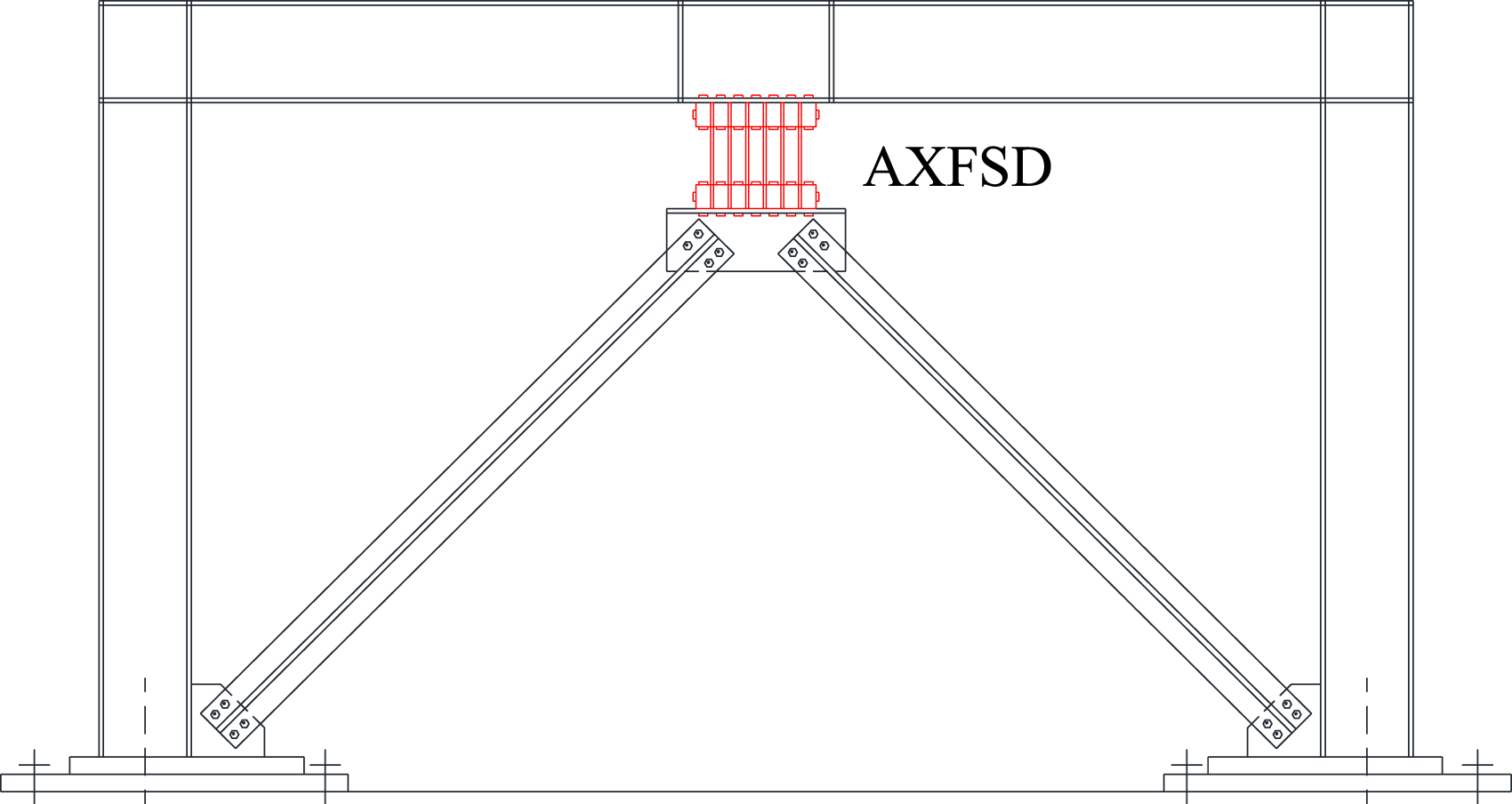
Working mechanism of the damper
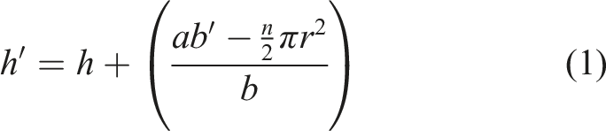
This subsection introduces the working mechanism of the proposed damper. Owing to the assembling manner, the X-shaped steel plates are constrained by the friction generated by the steel blocks. Hence, the boundary condition of the steel plates is deemed as semi-rigid restraint. In such a condition, the effect of the enlarged ends should be properly accounted for in the calculation of the effective height of the steel plates. Figure 3 shows the effective height of the X-shaped steel plates with semi-rigid boundary conditions. Effective height of X-shaped flexural steel plate.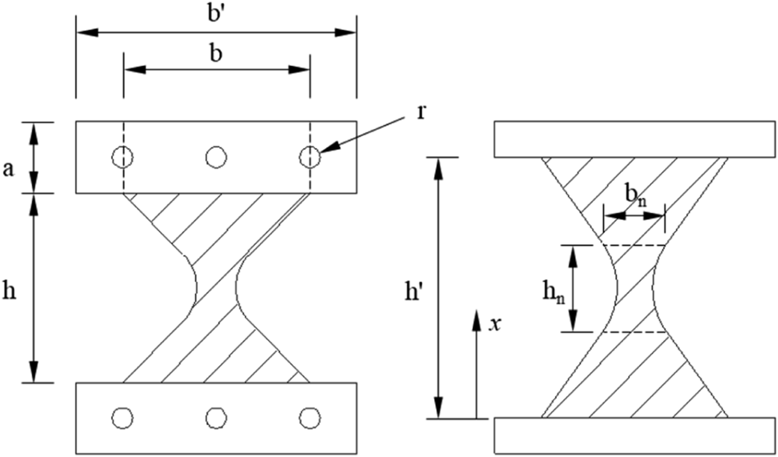
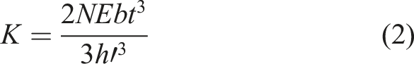
This paper suggests the following equation to calculate the effective height of steel plate, hʹ:
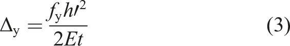
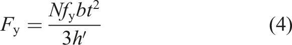
With the obtained hʹ, the initial stiffness, K, yielding displacement, Δ
y
, and yielding strength F
y
, can be readily calculated:
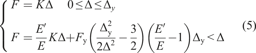
Assuming the steel has a bilinear elasto-plastic constitutive model, the skeleton curve of the damper is given as:
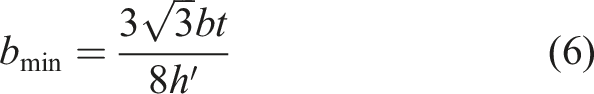
To transfer axial and shear forces, the minimum width of the X shape steel plate, bmin, is given as:
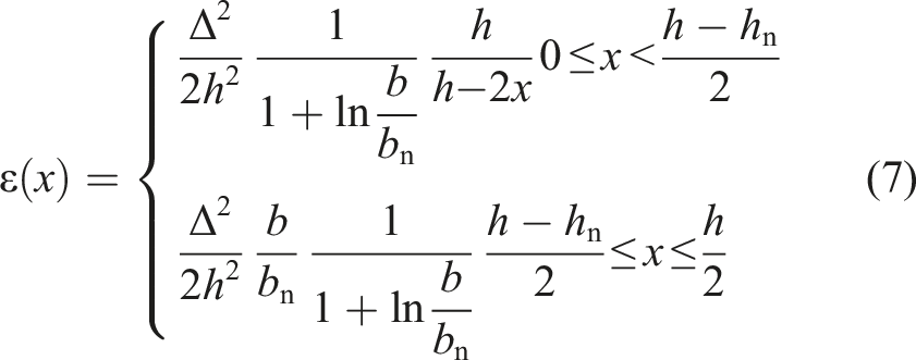
It is noted that membrane force would be induced when the damper is under large deformation. At a deformation of Δ, the membrane strain is calculated by:
With the increase of lateral deformation, the membrane force will be increased until it exceeds the static friction force between the steel blocks and steel plates. At this critical condition, the steel plate begins to slip until it is restrained by the steel threaded rods. Plastic deformation will be induced around the bolt hole, and it may lead to ovalization phenomenon, as illustrated in Figure 4. Ovalization of bolt hole at the enlarged end of the steel plate.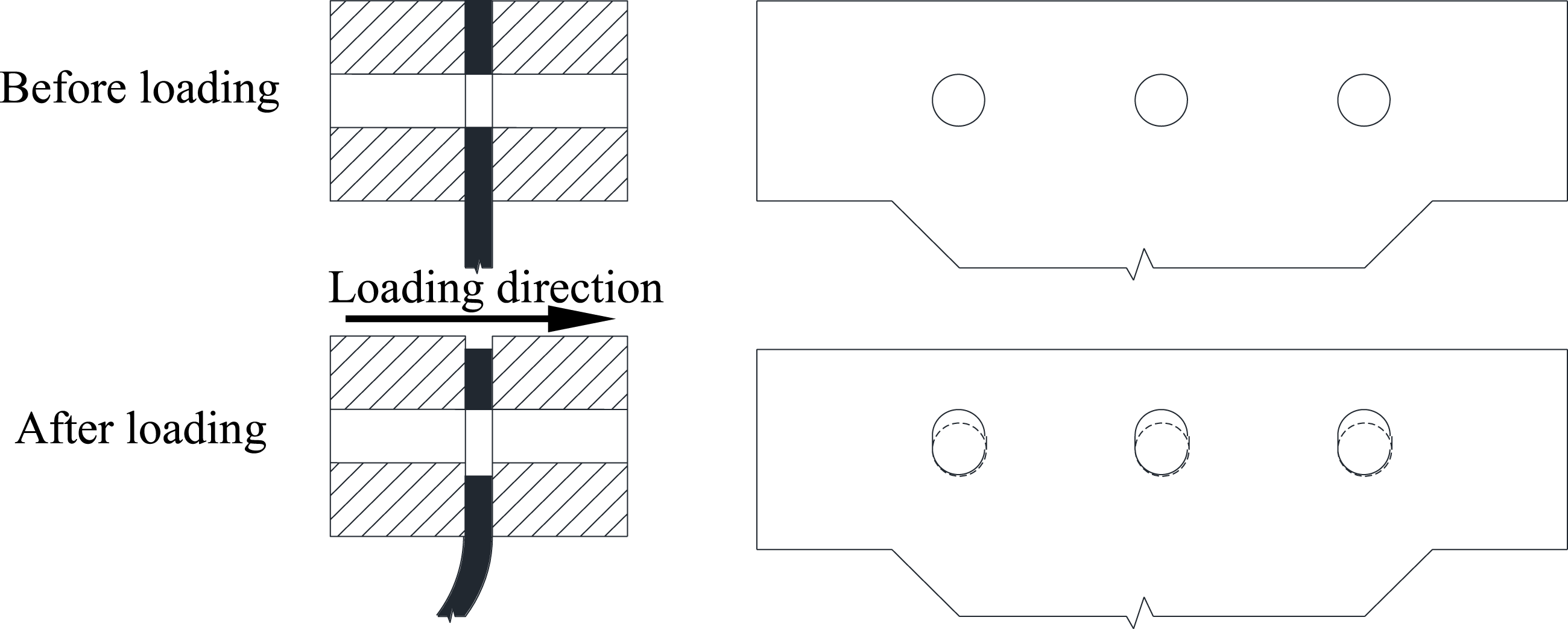
Cyclic loading tests
Specimen
To obtain the cyclic behavior of the proposed damper, one reduced-scale specimen was fabricated. As shown in Figure 5, the specimen had a global dimension of 410 mm × 300 mm × 350 mm (length × width × height). A total of six steel plates were utilized. These plates were made of Q235 steel with a nominal yielding stress of 235 MPa and were machined into X shape by wire cutting. The enlarged end of the steel plate had a dimension of 300 mm × 75 mm × 10 mm (width × height × thickness). The X shaped steel plates had a dimension of 200 mm × 200 mm × 10 mm (width × height × thickness). The minimum width of the steel plate was 33 mm. There were three bolt holes with a diameter of 22 mm and a distance of 100 mm. The steel blocks were made of Q345 steel with a nominal yielding stress of 345 MPa and had a dimension of 75 mm × 50 mm × 300 mm (height × width × length). The position of the bolt holes meets the requirement of the Chinese standard GB 50017-2017 (2017). A total of six steel threaded rods were fabricated by the 35CrMo steel with a nominal yielding stress of 835 MPa. The steel rods had a length of 460 mm and a diameter of 20 mm. The threaded length was 30 mm at both ends. Dimension of AXFSD (unit: mm): (a) front view; (b) side view; (c) top view; (d) X-shape steel plates.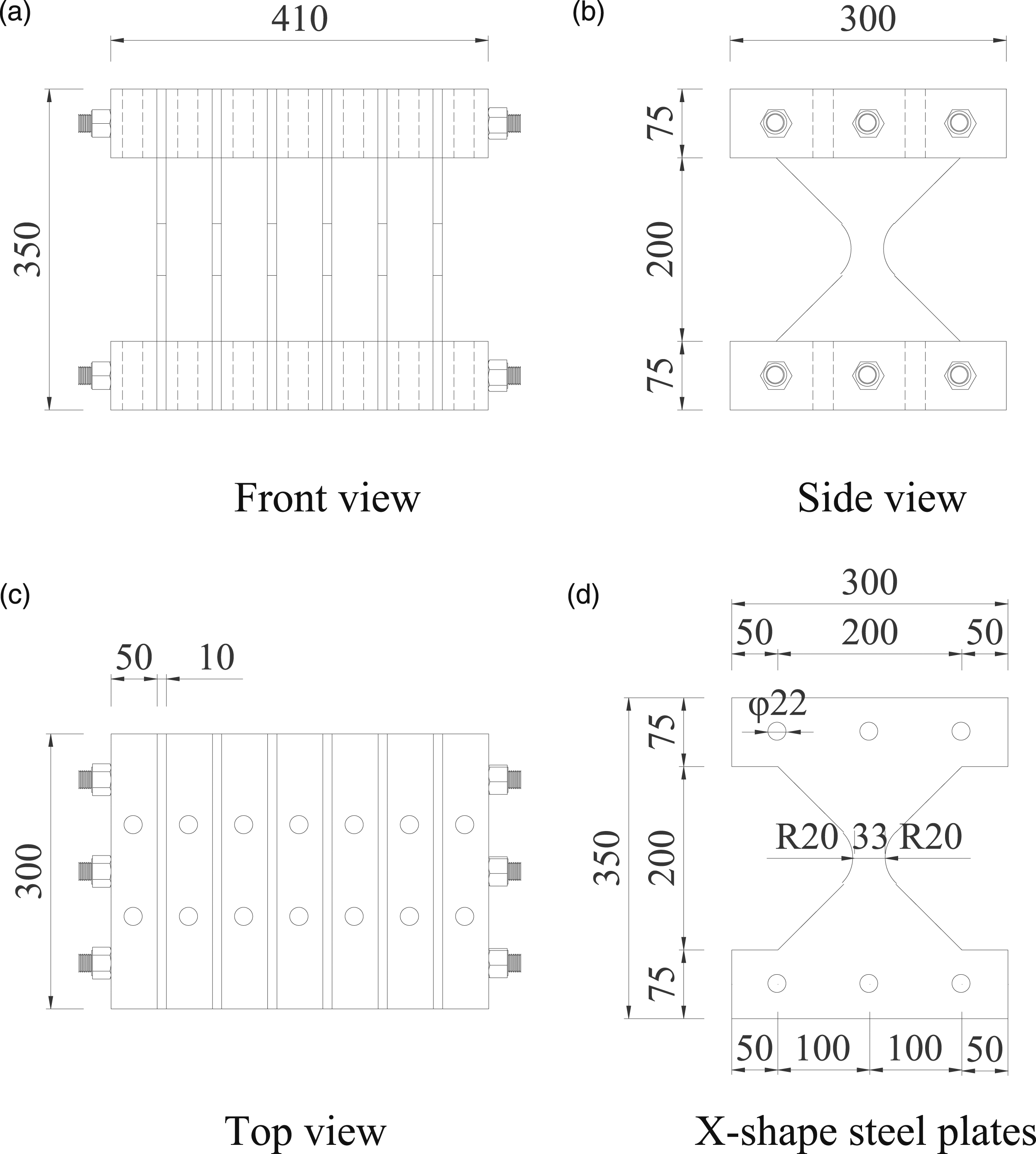
Material properties
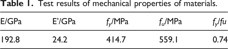
Test results of mechanical properties of materials.
Experimental setup and loading protocol
The test was conducted in the key laboratory of urban security and disaster engineering of ministry of education affiliated with Beijing University of Technology. Figure 6(a) and (b) show the schematic and photo of the experimental setup, respectively. The specimen was installed with a four-bar linkage experimental setup, which is able to apply horizontal deformation and meanwhile avoiding vertical deformation. The specimen was assembled and then mounted on a loading beam. The loading was applied by a hydraulic actuator, which has a capacity of 500 kN and a stroke of ±100 mm. Experimental setup: (a) schematic; (b) photo.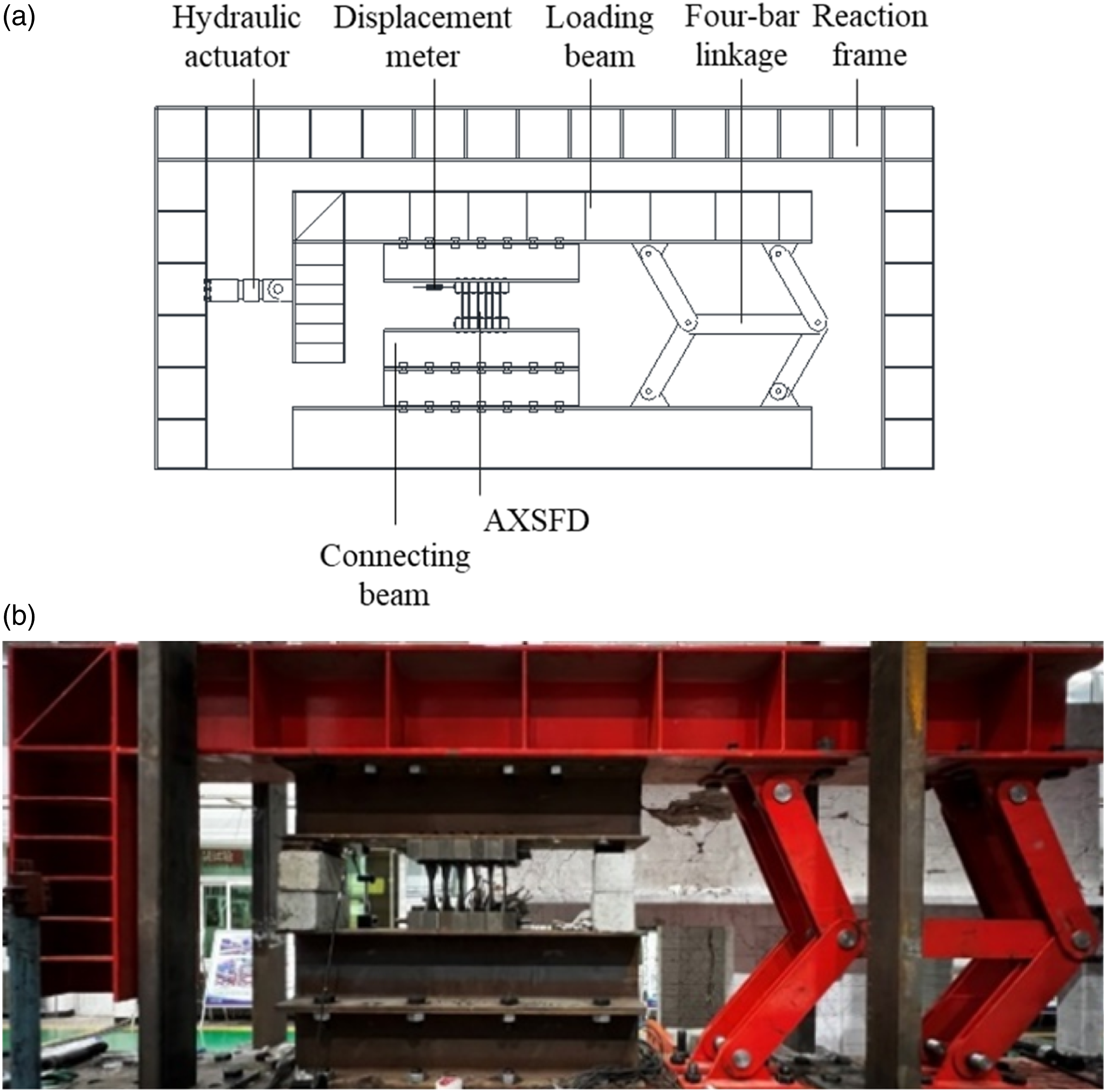
As shown in Figure 7, the loading protocol is a displacement-based one. The yielding displacement, Δ
y
, of the damper is estimated to be 10 mm by equation (3). The loading displacement begins with 0.5Δ
y
(5 mm) and ends with 10Δ
y
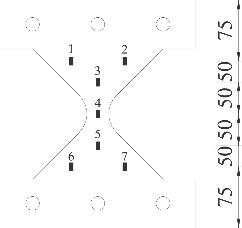
(100 mm) with an increment of 5 mm. Each loading amplitude is applied twice. The loading rate is 1 mm/s. The actual deformation applied to the damper was monitored by a linear variable differential transformer (LVDT). Figure 8 shows the strain gauges glued on the surface of one steel plate. The layout of the strain gauges has an equal distance of 50 mm along the vertical direction. Loading protocol. Arrangement of strain gauges (unit: mm).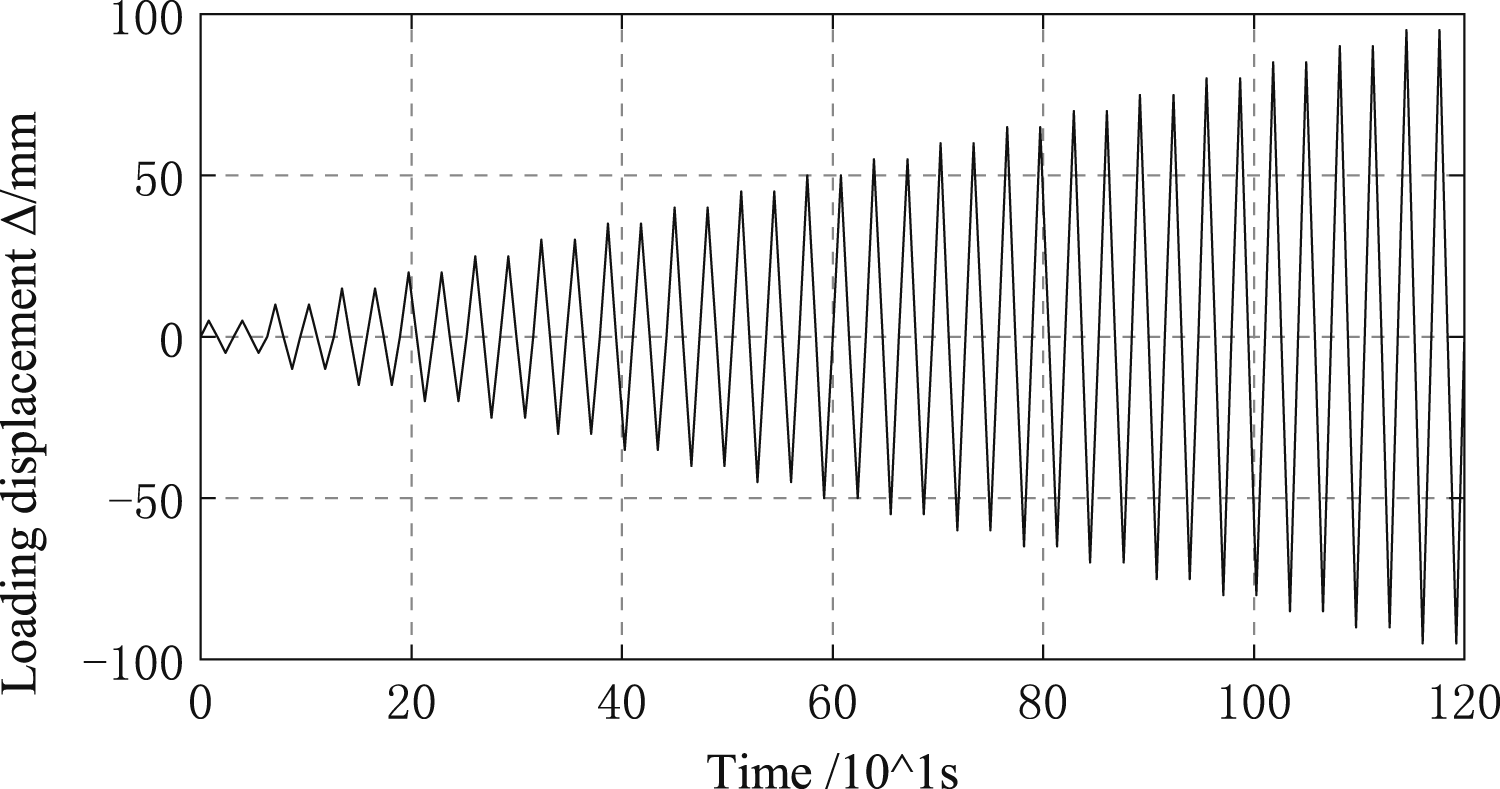
The anti-fatigue behavior is an important indicator to assess the mechanical performance of damper. To evaluate the anti-fatigue performance of the proposed damper, fatigue loading tests are needed. For example, FEMA 461 (2007) suggests a loading protocol for evaluating the low-cycle fatigue failure. Specifically, prior to the formal fatigue tests, a monotonic test is conducted to obtain the ultimate displacement Δu. The fatigue tests have two steps: 1) apply 10 loading cycles with a constant displacement amplitude of 0.1Δu; 2) the displacement amplitude becomes a step-wise increasing one, which is 1.2 times that of the former one. Each amplitude is repeated by three cycles. However, the current testing purpose is to reveal the basic cyclic behavior of the proposed damper, whereas the fatigue performance is not included and requires more work in future.
Experimental observations
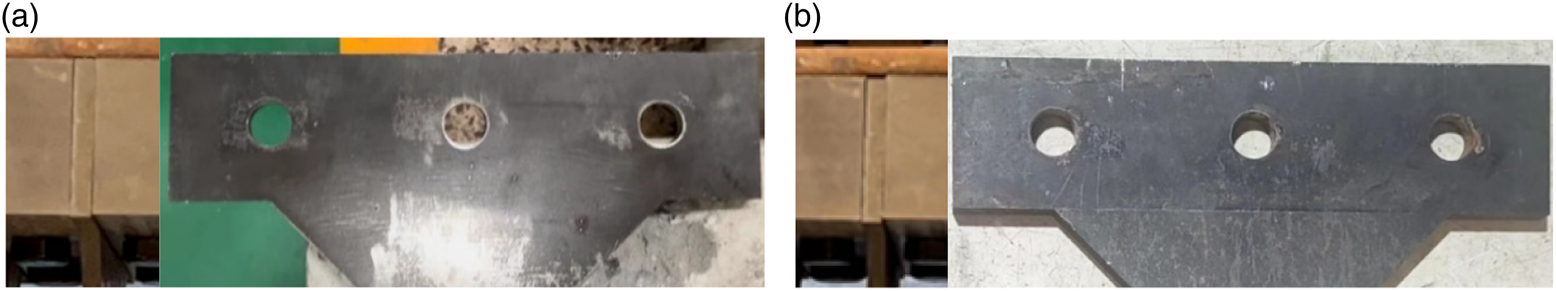
Figure 9(a) shows the initial shape of the damper. Due to the manufacturing error, the enlarged ends of the steel plates were not fully clamped by the steel blocks, and the gap was measured to be approximately 1.0 mm. Initially, the steel plates were straight. With the increase of loading deformation, the X-shaped steel plates exhibited remarkable bending deformation when the loading amplitude was 60 mm, as shown in Figure 9(b). There was no slippage between the specimen and loading beam. All the steel plates exhibited identical bending deformations. Hence, it indicates that the assembling manner was reliable. When the loading amplitude was increased to 95 mm, the output force of the damper reached 150 kN, which was close to the loading capacity of the hydraulic actuator. Hence, the loading process was paused and the applied deformation was gradually decreased to zero. During the entire loading tests, neither the fracture of the steel plates nor the slippage of bolts occurred. At the end of the tests, the steel plates were dismantled from the damper. Figure 10 compares the bolt hole before and after the test. Ovalization was not noticed, which means the steel plates had sufficient thickness to avoid causing plastic strain. Deformation of AXFSD: (a) initial shape: (b) deformation at 60 mm. Shapes of bolt holes: (a) before test; (b) after test.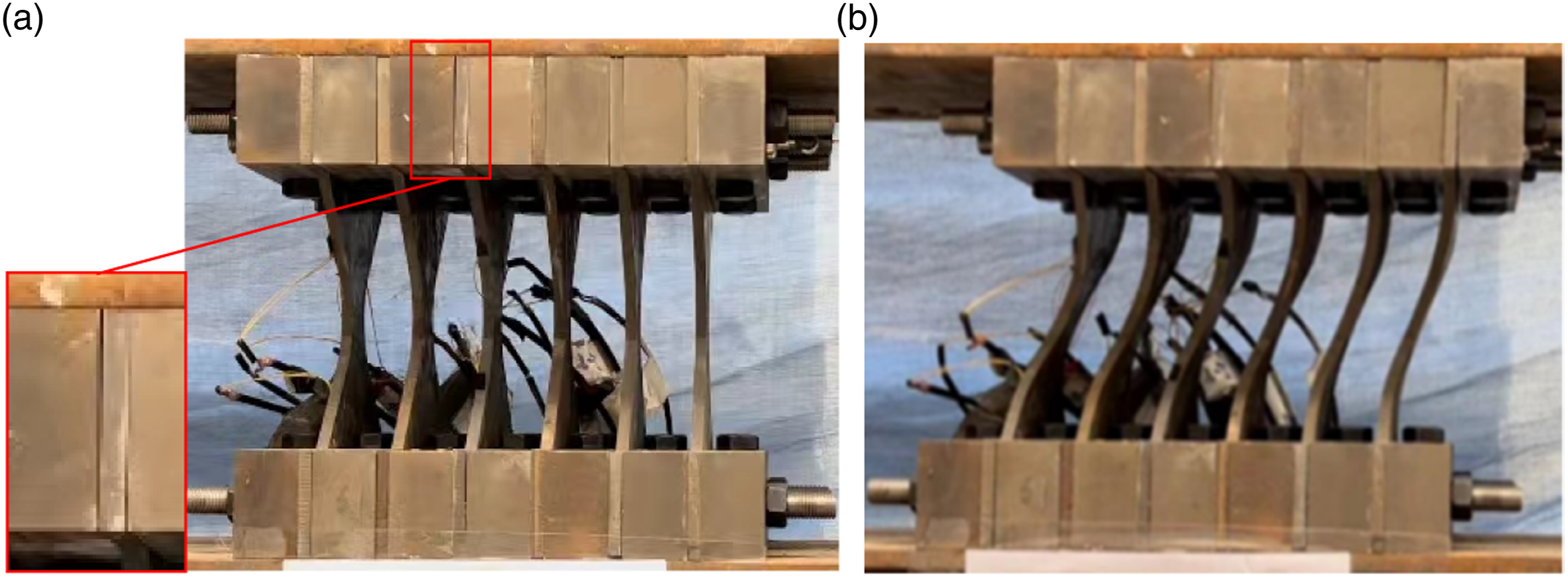
Experimental results
Hysteretic curves
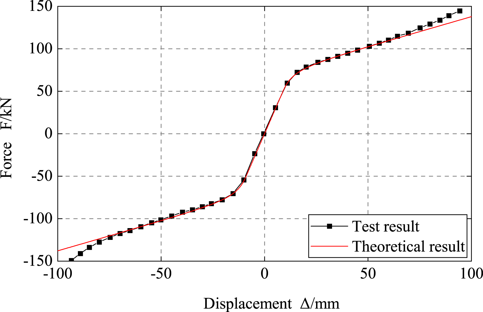
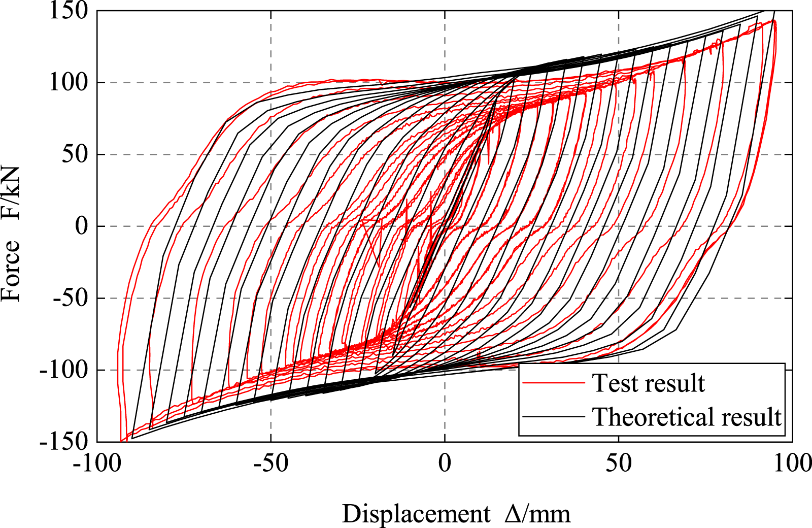
Figure 11 shows the hysteretic curves of the damper. As can be seen, the proposed damper has a symmetric full hysteretic behavior. During the entire loading tests, capacity degradation is not detected. Due to the gap between the steel blocks and steel plates, the hysteretic curves exhibit a slight slippage of approximately 1∼2 mm. At the displacement of 10.3 mm, the damper yields with a strength of 56.5 kN, which validates the analytical equation. When the loading displacement is increased to approximately 80 mm, the axial force in the steel plates induces the membrane effect and the damper exhibits noticeable strain hardening behavior. At the maximum loading displacement, the strength is up to 150 kN and the corresponding ductility is 9.3. The totally accumulated ductility is 808.4. Based on the hysteresis curves, the skeleton curve is generated, as shown in Figure 12. A comparison is made between the experimental and analytical results. It is found that yielding strength and yielding displacement can be well predicted, but the ultimate strength is underestimated. This is because the kinematic hardening behavior of steel is not considered by the analytical method. Hysteretic curve of AXFSD. Skeleton curve of AXFSD.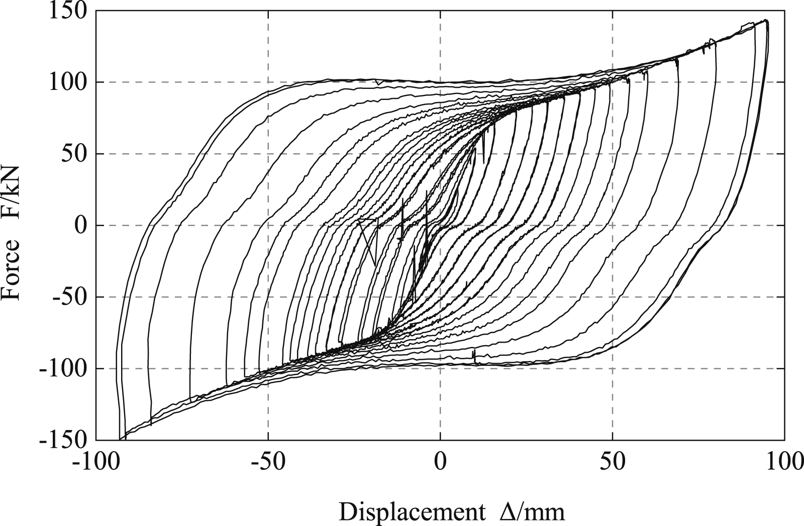
Stain analysis
As shown in Figure 8, the strain gauges were symmetrically glued with respect to strain gauge #4. When the loading displacement exceeded 65 mm, the strain readings were larger than the measuring range and some strain gauges were damaged. Hence, only the readings associated with loading displacement within 60 mm are presented. Figure 13 selects the height-wise strain readings associated with the loading displacements of ±10 mm, ±20 mm, ±40 mm and ±60 mm, respectively. The y axis is the distance from the strain gauges to the neutral line. The red dashed line, which corresponds to a strain of 0.2%, represents the yielding threshold. Strain distribution of X-shaped flexural steel plate.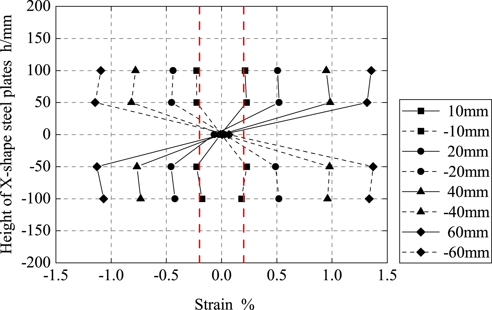
The readings of strain gauge #4 are constantly nearly zero, because it is close to the inflection point. During the entire loading procedure, the strain readings are symmetric, which is consistent with the symmetric hysteretic behavior observed in Figure 11. At the loading displacement of 10 mm, except for the strain gauge #4, the strain readings are approximately 0.2% meaning the cross section at different heights yield simultaneously. With the increase of loading displacement, the strain readings at the distances of ±100 mm are slightly smaller than that at the distances of ±50 mm. This is due to the more significant membrane effect at the regions closer to the fixed ends.
Energy-dissipating capacity
The energy-dissipating capacity reflects how well the damper could absorb the input seismic energy. This section quantifies the hysteretic energy and equivalent damping ratio of the damper. The slippage behavior did not dissipate energy and the slippage displacement was subtracted from the total displacement. Considering each loading amplitude was applied twice, the average result was calculated and presented. Figure 14 plots the hysteretic energy and equivalent damping ratio as a function of loading amplitude. As can be seen, after yielding, the hysteretic energy accumulates constantly with the increase of loading amplitude. At the maximum loading displacement, the hysteretic energy is up to approximately 33.6 kJ. The totally accumulated hysteretic energy is 235 kJ. The equivalent damping ratio also increases with the accumulation of hysteretic energy. At the loading displacement of 80 mm, the equivalent damping ratio is up to 42%. Energy-dissipating capacity and equivalent damping ratio of AXFSD.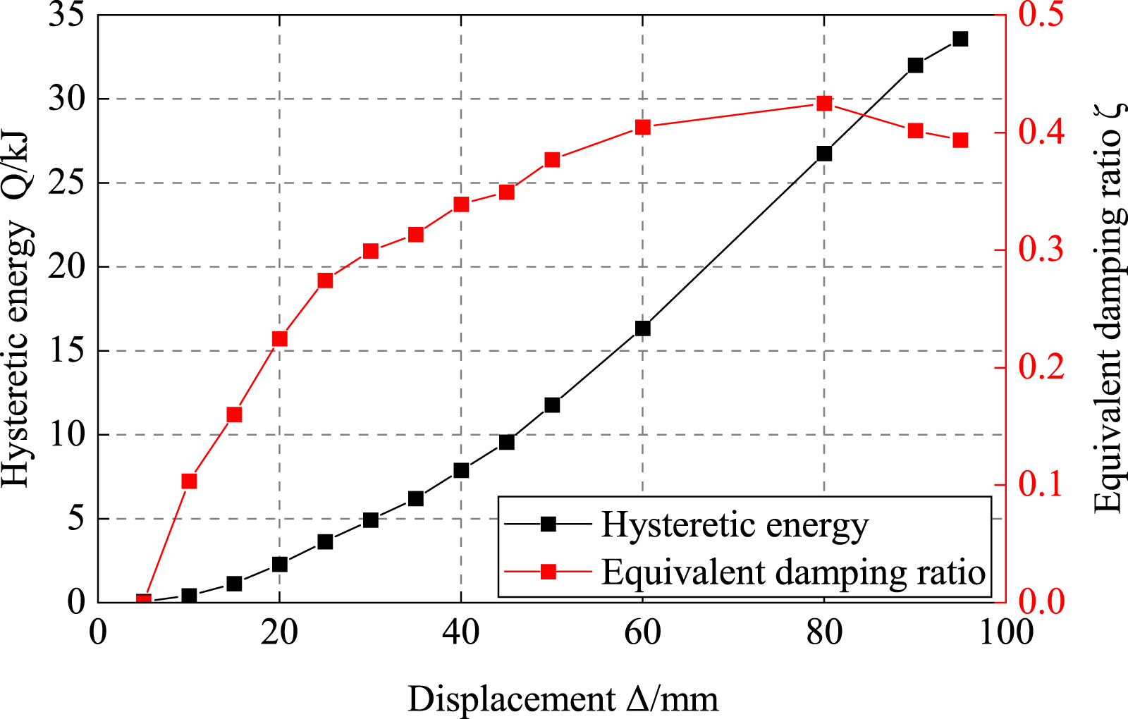
Numerical simulations
Numerical model
Compared with the experimental test, the FE analysis is more economical and flexible. The validated FE model can be used to explore the details that are challengeable to observe in experimental tests. Moreover, the stress and strain demand of the components, including the X-shaped steel plate, steel blocks and steel threaded rods, can be clearly revealed. Hence, numerical simulations were conducted by ABAQUS (2019). Figure 15(a) shows the meshed three-dimensional FE model. The dimensions of the FE model are identical to the specimen used in the test. All the components were simulated using the 8-node linear reduced-integration elements (C3D8R). The fine meshes were applied to the X-shaped steel plates and steel threaded rods to improve the accuracy of the numerical results, whereas the relatively coarse meshes were applied to the steel blocks and bolts to reduce computational cost. The contact property between the steel plates and steel blocks was simulated by ‘Surface to Surface’ contact. To simulate the friction constraint at the enlarged end of steel plates, the ‘Hard Contact’ and ‘Penalty Function’ were employed for the normal and tangential behavior of contact pairs, respectively. The friction coefficient was assumed to be 0.2 (JGJ 297-2013). For simplification purpose, the bolt connections were achieved by ‘Tie’. The fully constraint was applied to the bottom of the damper, whereas the loadings were applied on the top of the damper at a coupling reference point. All the steel components were assumed to have a bilinear elastoplastic model. For the steel plates, the elastic modulus and yielding stress were defined according to coupon test results. Regarding the other steel components, they were defined as elastic material with an elastic modulus of 206 GPa, because they remained elastic during the tests. As shown in Figure 15(b), the gap between the steel plates and steel blocks was represented by a 1 mm thick soft elastic material. The elastic modulus was assumed to be 1% that of the steel material. Finite element model of AXFSD: (a) meshed model; (b) gap modeling method.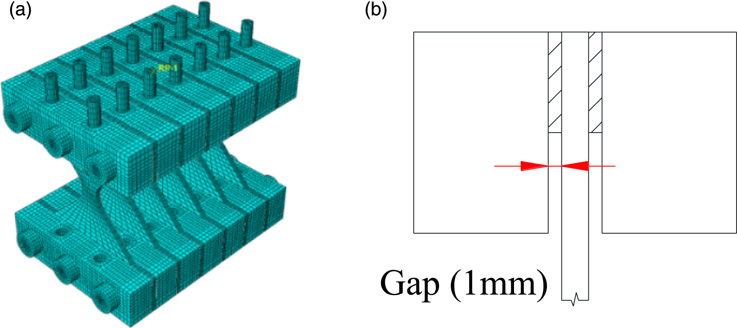
Simulation results
Figure 16 shows the deformation and stress contour when the damper is under the maximum deformation of 95 mm. Figure 16(a) indicates that the deformation mode is identical to that observed in the test. Figure 16(b) shows the stress contour of the steel plate, steel block and steel threaded rods. As can be seen, the steel plates yield simultaneously over the height. The stress demands of steel blocks and steel threaded rods are well below the yielding threshold, which are up to expectation. Figure 17 compares the hysteretic curves from simulation and test, which shows a good agreement with each other. This comparison also indicates that it is very challengeable to accurately reflect the slippage behavior. Displacement and stress contour of AXFSD: (a) deformation of 95 mm; (b) Mises stress of steel plate, steel block and steel threaded rods. Comparison of hysteretic curves.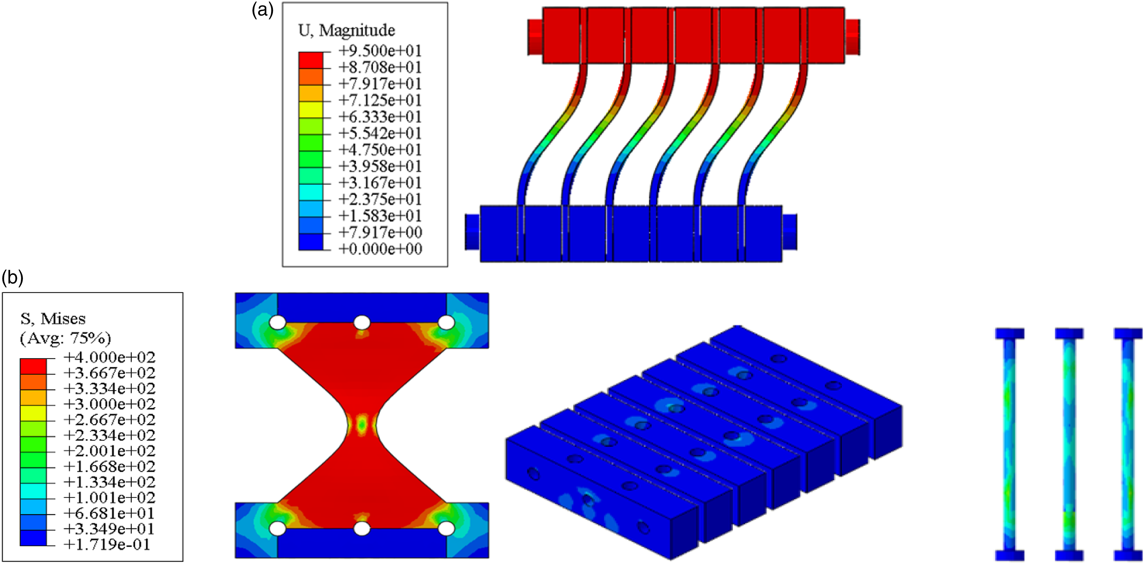
Parametric analysis
Based on the calibrated FE model, the parametric analysis was further conducted. The parameters of interest include the gap between the steel plates and steel blocks, the height and thickness of the steel plates. Considering the X-shaped steel plates have identical behavior, only one steel plate was simulated for reducing computational effort.
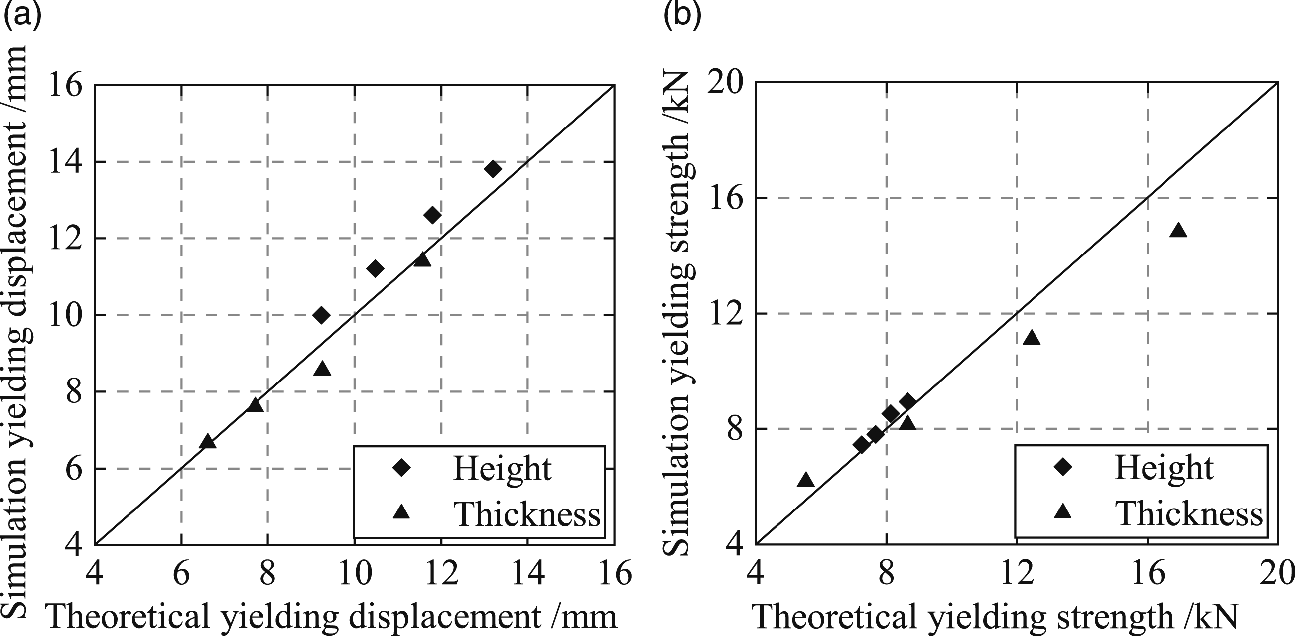
The results of parametric analysis are summarized in Figure 18. Figure 18(a) shows the hysteretic curves with different gaps, which were defined to be 0, 0.5 mm, 1 mm and 2 mm, respectively. As can be seen, increasing the gap decreases the initial stiffness and increases the yielding displacement. The ultimate strength is not affected by the gap. Hence, the gap should be eliminated for the proposed damper. Figure 18(b) assesses the effect of varying height of the steel plates. The considered heights were 200 mm, 220 mm, 240 mm and 260 mm, respectively. Increasing the height reduces the initial stiffness and increases the yielding displacement. Hence, at the same deformation, the steel plate with the largest height leads to the smallest strength. Figure 18(c) compares the hysteretic curves with the thickness of 8 mm, 10 mm, 12 mm and 14 mm. It shows that increasing the thickness of steel plate increases the initial stiffness and strength for the damper. To cross validate the accuracy of the proposed equation for the effective height of the steel plates, the yielding displacement and yielding strength are extracted from the hysteretic curves. Figure 19 compares the analytical and numerical results. As can be seen, the dots are around the 1:1 equivalent line, which means that they agree well with each other. The maximum errors of predicting yielding displacement and yielding strength are 7.6% and 4.7%, respectively. Hence, the comparison results confirm the reasonability of the proposed calculation method for the effective height. Parametric analysis results of AXFSD: (a) gap between the steel plate and steel blocks; (b) height of steel plate; (c) thickness of steel plate. Comparison between the analytical and numerical results: (a) yielding displacement; (b) yielding strength.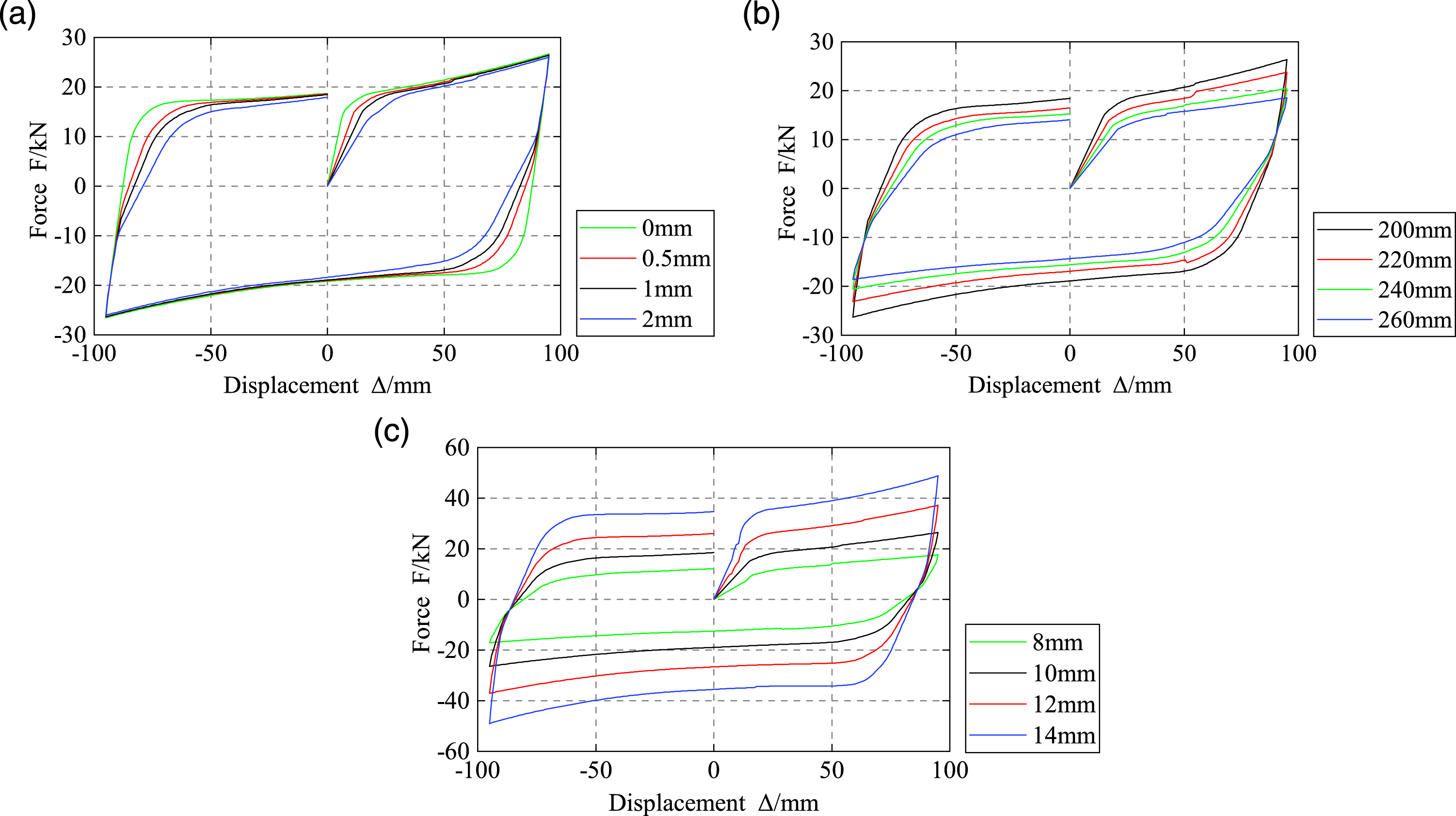
Seismic performance evaluation
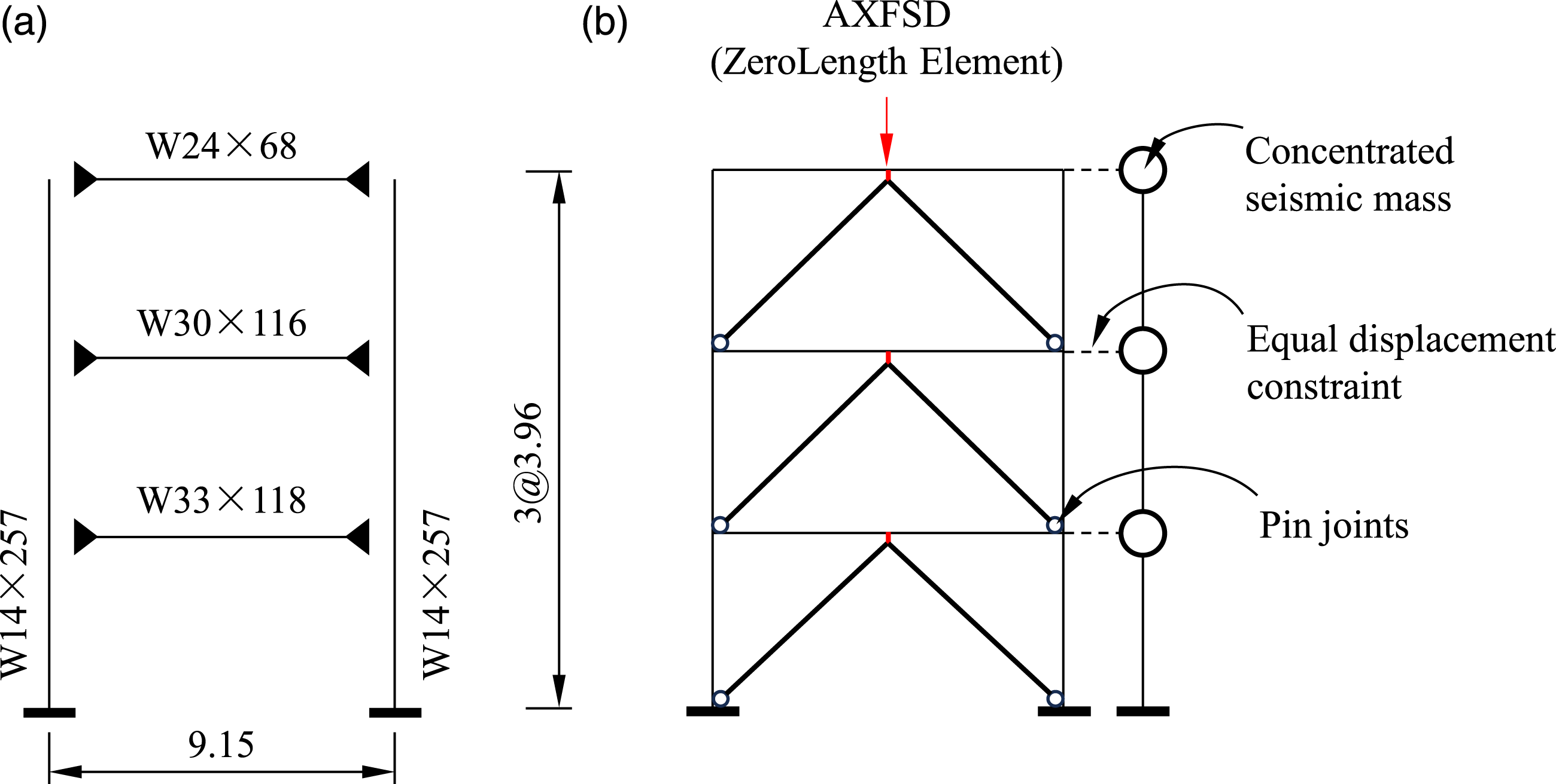
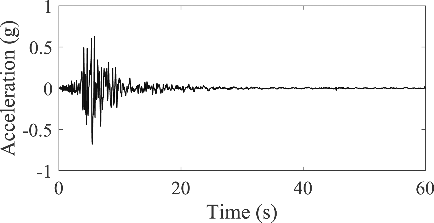
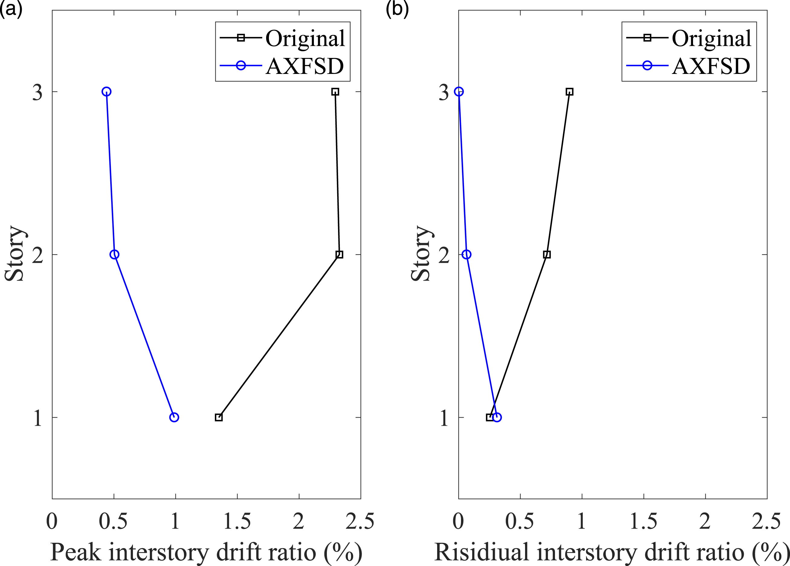
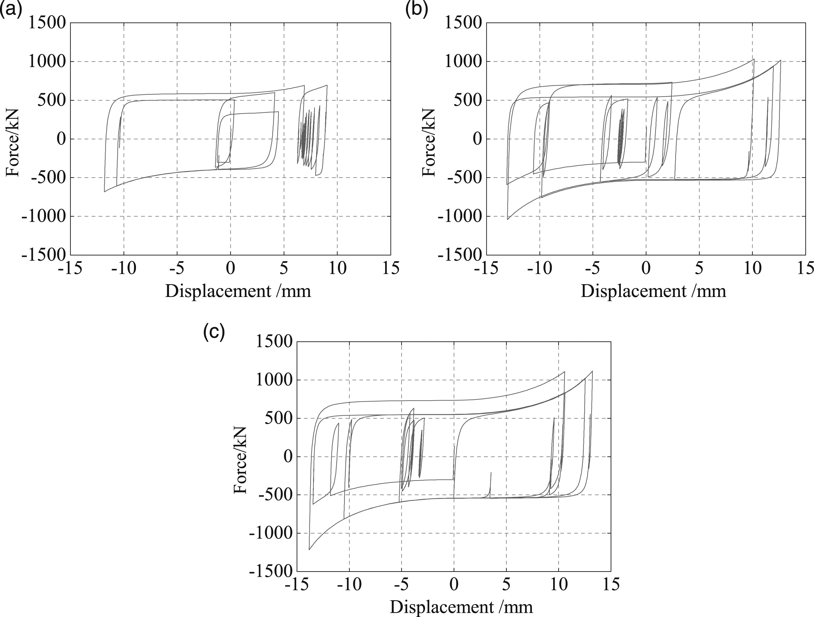
Based on a benchmark frame model (Ohtori et al., 2004; Qiu et al., 2020), nonlinear time history analysis was conducted to reveal the seismic response control efficacy of the proposed damper. The FE model of the proposed damper was firstly established in OpenSees (Mazzoni et al., 2006), and the calibrated model was further utilized for system-level analysis. The damper was simulated by the Cast material and the ZeroLength element. As shown in Figure 20, the simulation results agree well with the experimental data. Further, a 3-story frame building from Refs. (Ohtori et al., 2004; Qiu et al., 2020) was selected for demonstration purpose, as shown in Figure 21(a). Details of the frame can be found in the relevant studies. The FE model of the frame was also established in OpenSees, as shown in Figure 21(b). Notably, to avoid inducing bending actions, the supporting braces were hinged to the main frame. Figure 22 plots the acceleration time history of the selected earthquake ground motion record. This record was from Newhall of 1994 Northridge earthquake. The peak ground acceleration was 6.6 g and the duration was 59.98 s. Figure 23(a) shows that the height-wise peak interstory drift ratio is substantially reduced and is more uniform after retrofitting. Figure 23(b) plots the height-wise residual interstory drift ratio. It indicates that the residual interstory drift ratios are also decreased by the added dampers. Figure 24 plots the cyclic behaviors of the dampers. Comparison of OpenSees simulations and experimental data. Selected frame building: (a) dimension (m); (b) FE model. Acceleration time history of the selected earthquake ground motion record. Height-wise seismic responses: (a) peak interstory drift ratio; (b) residual interstory drift ratio. Cyclic behaviors of the dampers under the selected earthquake record: (a) 1st story; (b) 2nd story; (c) 3rd story.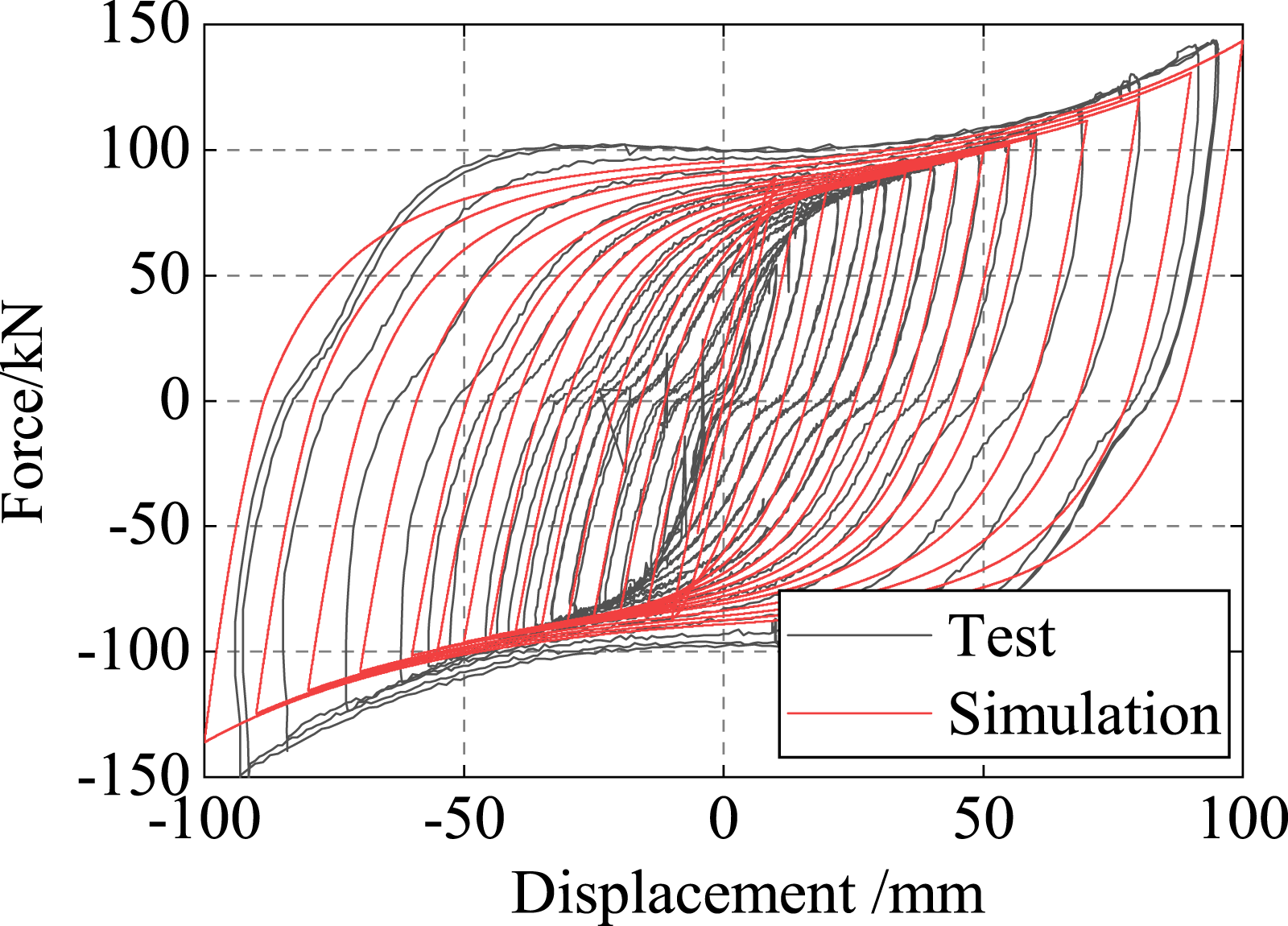
Conclusions
This paper proposes an assembled X-shaped flexural steel damper. In the analytical part, the equation for the effective height of the steel plate is suggested, and the equations for estimating initial stiffness and yielding strength are presented. Cyclic loading test was conducted on a reduced-scale specimen. Finite element analyses were conducted for reveal more details and parametric analysis. Finally, seismic performance evaluation was conducted. Following conclusions are obtained: 1) The damper exhibited anticipated deformation mode and stable hysteresis. For the testing specimen, the ductility is up to 9.3 and the maximum equivalent damping ratio is approximately 42%. 2) Both the analytical method and numerical simulation well agree with the experimental data. The theoretical equations and finite element model can be used for the design of the proposed damper. 3) The parametric analyses indicate that the equation for calculating the effective height of the steel plate is reasonably accurate, for a wide range of the gap values, the height and thickness of the steel plates. 4) Seismic performance evaluation indicates that the installation of the damper reduces both peak and residual interstory drift ratios for the protected frame building.
Footnotes
Declaration of conflicting interests
The author(s) declared no potential conflicts of interest with respect to the research, authorship, and/or publication of this article.
Funding
The author(s) disclosed receipt of the following financial support for the research, authorship, and/or publication of this article: This research was supported by the National Natural Science Foundation of China (Grant No.: 52178267). The opinions, findings, conclusions, and recommendations presented in this study are those of the authors and do not necessarily reflect the views of the sponsors.