
Abstract
Floating production storage and offloading systems (FPSOs) are gaining prominence in the offshore industry. FPSOs are generally designed to weathervane, necessitating surge vibration control for station keeping. Since the natural period of surge vibration is far higher than the dominant period of the input wave load, instead of supplemental damping, a high inertial device, such as the tuned mass damper inerter (TMDI), would be effective. This concept has hitherto not been investigated for the FPSO. A frequency domain formulation of the FPSO-TMDI system under wave force, considering interaction of the liquid cargo is presented. Utilizing Froude-Krylov theory, suitably modified to account for diffraction effects, wave force on the FPSO is obtained using field data from North Sea. TMDI parameters are optimized using Genetic Algorithm under different tank-fill conditions. The results demonstrate that the TMDI holds potential in providing an effective and robust performance in controlling the surge motion of FPSOs.
Keywords
Introduction
There is a heavy dependency of industries on ocean resources due to the constantly growing demand for oil and gas. The various types of fixed and moored offshore structures used for the production of oil and associated products include gravity structures, jacket platforms, jack-up rigs, spar platforms, compliant platforms, such as guyed towers, articulated towers and tension leg platforms, and floating offshore platforms (Chandrasekaran, 2015), out of which the floating production, storage and offloading systems (FPSOs) are increasingly becoming popular. This is attributed to their versatility for use in different water depths and ability to provide an economical solution, both in terms of cost and time, to the very challenging problem of oil exploration in deepwater and remote fields. This is chiefly due to their in-house storage capability of the crude oil in tanks located in the hull of the FPSO, which does away with the requirement of sub-sea pipelines for transport of the crude. FPSOs also possess the valuable advantages of mobility and relocatability, quick deployment, and independence from the sub-sea architecture for the particular field when turret mooring system and flexible production risers are used (Srinivasan et al., 2008). FPSOs are thus poised to play a crucial role in the offshore oil production scenario, and research to enhance their safety and productivity is daily gaining importance.
FPSOs are susceptible to various dynamic loads, such as those caused by waves, wind, currents, ice, earthquakes, tsunamis, of which wave loading is the most common. The slamming of waves on the hull causes damage and serviceability issues due to green water on the deck, and leads to fluid-structure interaction between the oil in the cargo tanks and the vessel that can aggravate the motions of the vessel. This can cause spillage of oil on the deck as well. The turret mooring system of the FPSO allows unconstrained 360° rotation of the FPSO vessel depending upon the direction of the incident wave. This can subject the FPSO to significant surge motion. The riser system is vulnerable to damage from excessive surge motion, that can cause the pipes to bend or break, leading to leaks or even complete failure of the production system. In addition to damaging the riser system, critical components of the FPSO, such as the mooring system, the hull and equipment can also be damaged. This results in costly downtime for repairs and potential environmental hazards, if there is a leak of crude oil or other hazardous materials. Therefore, it is important to examine means to control the surge response of the FPSO to ensure the safety of the production system.
So far, there is very limited work available on the vibration control of FPSOs. Damping of vibration and active noise control in FPSOs have been investigated by Olunloyo and Osheku (2012) by utilizing the mechanism of interfacial slip in the layered structural laminates in the internal configuration of the hull of the FPSO. The model for dissipation of vibrational energy considered by them is slip damping with heterogeneous sandwich composite viscoelastic beam-plate smart system. Amongst active, passive, semi-active vibration control techniques, passive vibration control devices, such as viscous dampers, tuned mass and liquid dampers (TMDs and TLDs), etc., are relatively inexpensive and easy to maintain. They are also more reliable in the harsh marine environment as they do not require electronic components. Surge vibration control of ship-shaped FPSOs using passive multiple TLDs has been studied by Gurusamy et al. (2019) and Gurusamy and Kumar (2019, 2021). In these works, the FPSO has been modelled by a SDOF system and the existing cargo tanks have been used as the TLDs. Several different configurations of these tanks have been considered. To achieve these configurations, partitioning of the tanks has been done, which, however, may not be practically feasible. The results have been presented by considering the cargo tanks to be full, which have provided a high mass ratio of more than 45%. This high mass ratio is vital for the performance of the TLD system because the period of surge motion of the FPSO and that of the input wave force are far apart from each other. However, the sloshing frequency, which is used for tuning purposes, is a function of the height of liquid in the tank, and will not remain constant, nor will the mass ratio, as the tanks undergo filling and offloading of liquid cargo. Further, it is reported that the control strategy is most effective when the tuning of the passive device is to the dominant frequency of wave excitation, and not to the structural frequency, which follows from the principle of the dynamic vibration absorber and the fact that the forcing and structural frequencies are well-separated from each other. Apart from the conventional ship-shaped FPSOs, there have been studies to reduce the heave motions of cylindrical FPSOs, by means of a heaveplate, which is an external appendage plate surrounding the base of the main hull of the FPSO (Amin et al., 2022; Sathia and Vijayalakshmi, 2020; Subbulakshmi et al., 2015).
In the present study, the FPSO is a ship-shaped moored vessel, and is subjected to regular waves in deep sea conditions. According to DNV (DNV-RP-F205, 2010), the natural period of surge motion of ship-shaped FPSOs is more than 100s, which is far higher than the period of the input wave force for different sea state conditions (Jahanmard et al., 2013). Thus, in such a scenario, the dynamic response of the structure cannot be reduced by an increase in damping alone, rather a high inertia is required for the purpose. It is not feasible to equip a conventional TMD, which is a well-established passive control device, with a very high mass ratio. Again, as discussed above, the mass of the liquid cargo of the FPSO is variable and hence cannot always be relied on to provide a large inertia. This issue can be resolved by the use of a tuned mass damper inerter (TMDI), in which the TMD is connected to the primary structure and a two-terminal inerter device, one of which is attached to the TMD mass and the other is either grounded or attached to the primary structure (Weber et al., 2020).
The TMDI was first proposed as a novel passive damper by Marian and Giaralis (2013, 2014) for mitigating lateral structural vibrations. An ideal inerter is a weightless linear two-terminal mechanical element that develops a force that is proportional to the relative acceleration between its terminals, and the constant of proportionality has the unit of mass and is called inertance. The conceptualization of different mechanisms that could produce realistic inerter devices was given by Smith (2002). A wide variety of inerters have since been technologically prototyped and experimentally validated, such as ball-screw, rack-and-pinion, helical fluid, gyro-mass damper, living-hinge, hydraulic inerter, etc. (Kaveh et al., 2020), which can produce significantly high inertance in comparison to the physical mass of the inerter. The value of the inertance ratio, defined as the ratio of the inertance to the structural mass, as high as unity can be produced (Kaveh et al., 2020; Marian and Giaralis, 2014; Pietrosanti et al., 2017; Ruiz et al., 2018). The inerter has recently been widely researched for lateral structural vibration mitigation. For example, it has been incorporated in the various vibration control systems investigated for the seismic response mitigation of liquid storage tanks. Luo et al. (2016) studied a hybrid control mechanism comprising a viscous mass damper and rubber bearing for reducing the sloshing of liquid in a seismically excited cylindrical tank. The viscous mass damper has an inerter and an inner tube coated with viscous fluid connected with a ball screw. Another hybrid control system with base isolation and TMDI was proposed by Labaf et al. (2022) for mitigating seismic-induced severe structural damage of steel storage tanks. A comparative vibration control study of the base-isolated water tank equipped with linear viscous damper, viscous mass damper and negative stiffness damper subjected to seismic isolation was carried out by Zhu et al. (2023). Further, Islam and Jangid (2023) have proposed a novel negative stiffness and inerter damper for the control of seismic-induced response of concrete elevated liquid storage tanks. The inerter has also been gaining popularity in the offshore industry. Amongst various offshore platforms, chiefly floating wind turbines (Fitzgerald et al., 2023; Hu and Chen, 2017; Hu et al., 2018; Li et al., 2021; Sarkar and Fitzgerald, 2019, 2022; Villoslada et al., 2020; Zhang and Høeg, 2021) semi-submersibles (Ma et al., 2020a; 2020b) and jacket structures (Xu et al., 2023) have been investigated for vibration control by the inerter.
Observing the recent trend in the application of the TMDI in offshore structures, coupled with the need for a very large inertia in case of surge response control of the FPSO, this study investigates the performance of a TMDI device coupled to the FPSO with varying fill conditions of the cargo tanks. The fluid-structure interaction between the liquid cargo and the FPSO vessel is considered by adopting a standard equivalent mechanical model for the tanks. In what follows, firstly, a brief description of the working principle of the TMDI is given. Next, the modelling of the FPSO-TMDI system is presented, followed by the formulation of the equations of motion and the frequency response functions (FRFs) of the uncontrolled and controlled FPSO. Time domain and frequency domain studies on an example FPSO are then carried out, with descriptions of the considered wave force, optimization studies and performance analysis of the TMDI. Lastly, conclusions derived from the work are presented.
Operational mechanism of TMDI
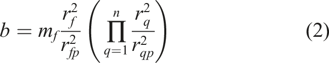
The resisting force, F
r
, produced by the inerter is expressed as follows Illustration depicting (a) a rack-and-pinion flywheel-based inerter apparatus with four gears, and (b) a single gear rack-and-pinion flywheel-based inerter (Marian and Giaralis, 2017).

Modelling of FPSO-TMDI system
A schematic diagram of a moored FPSO is shown in Figure 2(a). In this study, the FPSO vessel is assumed to possess the shape of a rectangular block. The various dimensions of the FPSO, namely, the length (L), maximum beam (B), height (H) and draft (D), which is the vertical distance between the waterline and the bottom of the FPSO vessel, are given in Figure 2(b). The hull of the FPSO houses identical crude oil storage tanks (see Figure 2(c) for an indicative arrangement), with L
t
, B
t
and H
t
denoting the length, breadth and height of a single tank. (a) Schematic diagram of a moored FPSO, (b) 3D view of a typical FPSO, (c) plan and elevation of an indicative crude oil storage tanks’ arrangement in the hull.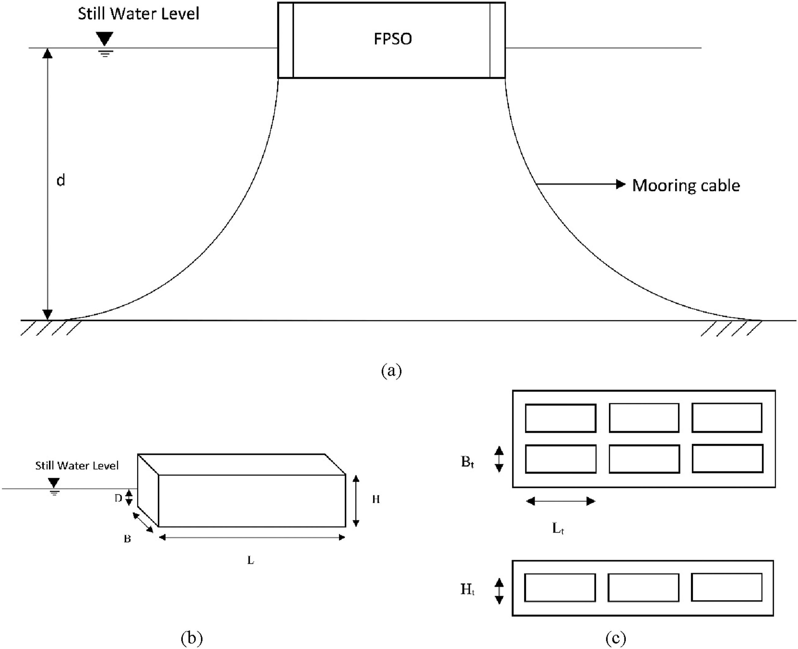
The finite element modelling of FPSOs with storge tanks in the hull requires a considerable number of degrees of freedom, making the computational analysis highly tedious. Hence, the lumped mass model is being considered in studies on the FPSO under unidirectional wave excitation (Duggal et al., 2011; Gurusamy et al., 2019; Gurusamy and Kumar, 2021). Further, a liquid-containing tank under lateral excitation is commonly modelled by mass-spring-dashpot systems representing an impulsive or “dead” mass, and a series of sloshing masses, with the fundamental sloshing mode predominating (Ibrahim et al., 2001). With this background, in this study, a 2-DOF lumped mass model of the crude oil filled-FPSO is considered (see Figure 3(a)). The first DOF represents the surge motion of the empty FPSO, along with the impulsive mass of liquid in the oil tanks, and the second DOF represents the displacement of the liquid sloshing mass in the fundamental mode. The total impulsive and sloshing masses are obtained by adding the individual contributions of the tanks. In Figure 3(a), m1 denotes the mass of the empty FPSO along with the impulsive liquid mass, m2 is the total sloshing mass (see Equation (3)), k1 is the stiffness of the mooring cables, k2 is the total sloshing stiffness (see Equation (4)). Further, c1 is the damping coefficient of the FPSO, and c2 represents the damping coefficient associated with the liquid sloshing mode. p
w
denotes the wave load acting on the FPSO. Mechanical idealization of FPSO, (a) without, and (b) with incorporation of TMDI system.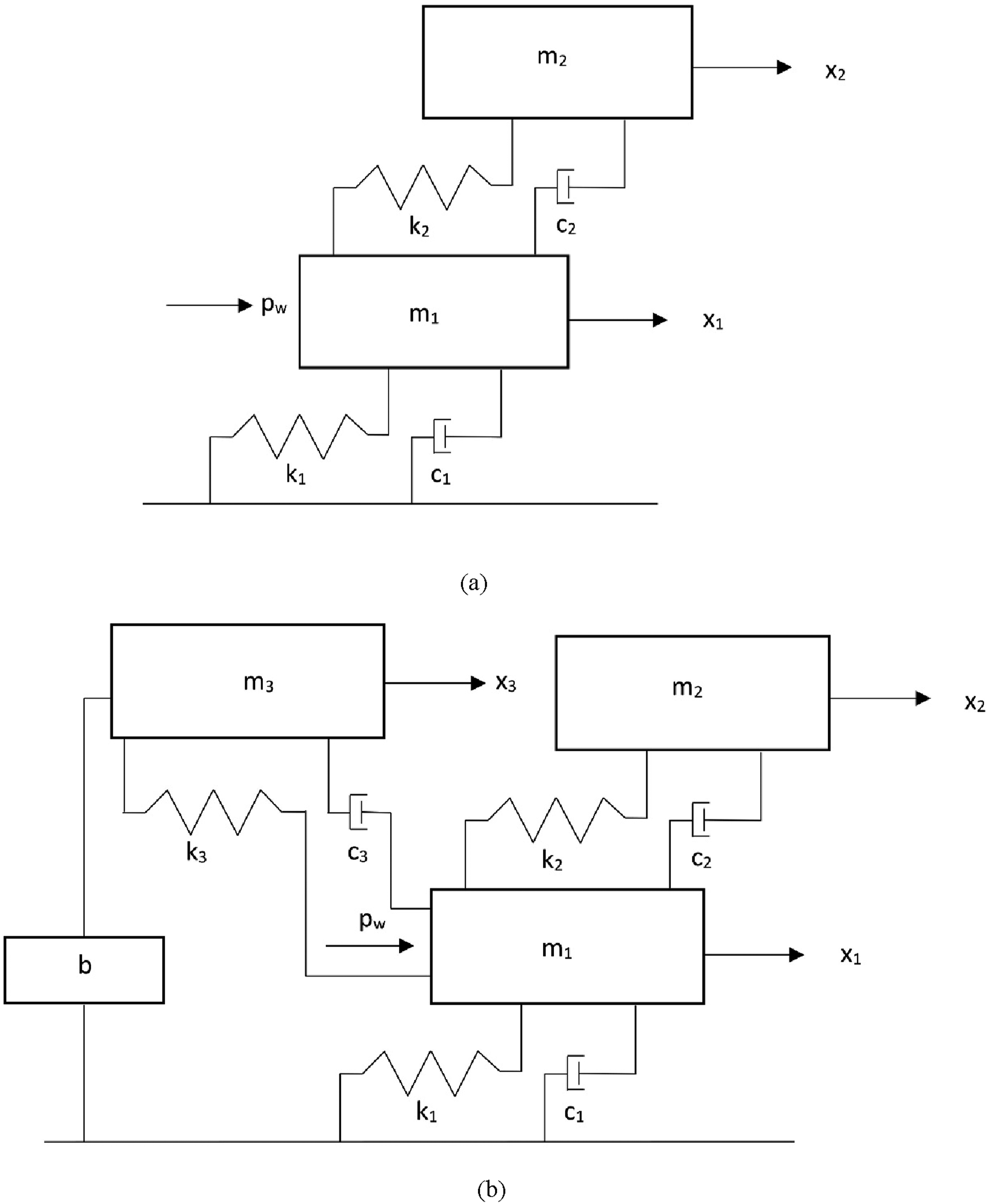
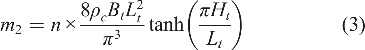
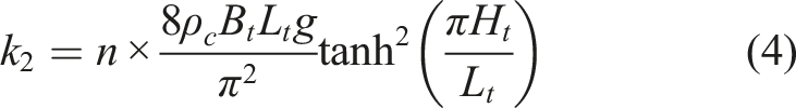
Here, n denotes the number of tanks in the hull of the FPSO, g is the acceleration due to gravity and ρ c represents the density of crude oil.
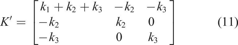
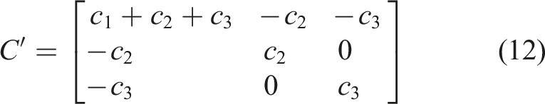
With the incorporation of the TMDI on the FPSO, an additional DOF is introduced. The 3-DOF lumped mass model of the FPSO-TMDI system is depicted in Figure 3(b). Here, k3 and c3 respectively denote the linear lateral stiffness and viscous damping coefficient of the elements supporting the secondary mass m3 of the TMD on the deck of the FPSO. The inerter has a terminal connected to the mass m3 and the other terminal is assumed to be grounded. This is a simplistic assumption, which to some extent may be considered reasonable if this terminal is connected to a cable at sufficient depth where the wave loads are small, or to a point on the turret mooring system that experiences low acceleration. It is, in fact, extremely challenging to locate such “fixed” objects in deep-water environments where FPSOs are stationed, especially when the surrounding structures also share floating characteristics.
Formulation of equations of motion and frequency response functions
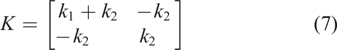
The equations of motion for the 2-DOF lumped mass model of the uncontrolled FPSO subjected to regular wave load are provided by


Similarly, the equations of motion for the 3-DOF lumped mass model of the FPSO-TMDI system subjected to regular wave load are provided by


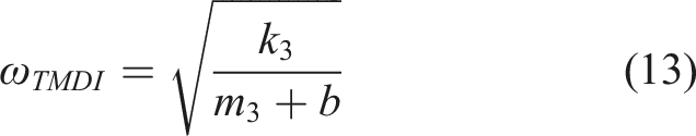
Let ω
TMDI
and ζ
TMDI
denote the natural frequency and equivalent viscous damping ratio of the TMDI system, respectively, defined by

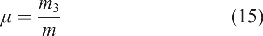
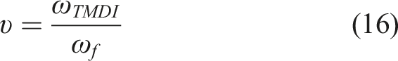
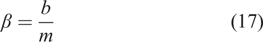
Next, the mass, tuning, and inertance ratios are denoted by μ, υ and β respectively, and are expressed as
Now, in order to conduct a frequency-domain analysis, the following input-output equation for the uncontrolled FPSO model is obtained by applying Fourier transformation to equation (5).

Here, {X(ω)} and {P
w
(ω)} are the vectors of the Fourier transforms of the displacement and wave force, and are provided in equations (19) and (20), respectively. [H(ω)] is the matrix of complex frequency response functions (FRFs) of order (2×2), presented in equation (21).
Here, X i (ω) and P w (ω) represent the Fourier transforms of the time-dependent variables, x i (t) and p w (t), (i=1 to 2), respectively. In equation (21), H11(ω) is the FRF of the displacement of m1, in the 2-DOF lumped mass model depicting the uncontrolled FPSO, under the wave force acting on m1.
Similarly, the Fourier transformation of equation (9) leads to the following input-output relation of the FPSO-TMDI system model.

Here, vectors {X′(ω)} and


Here,
Numerical study
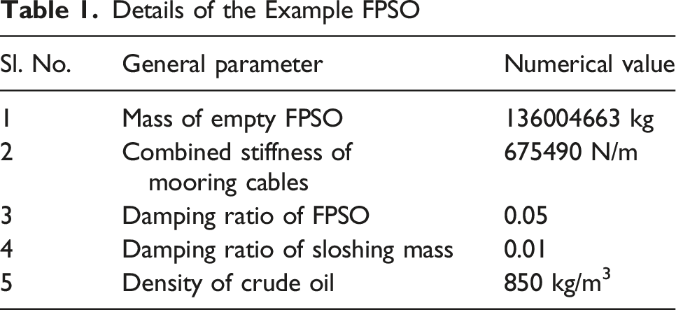
In this section, the performance of the TMDI system coupled with an example FPSO taken from literature (Gurusamy et al., 2019), positioned in the North Sea, exposed to regular wave excitation, is demonstrated. The subsequent sub-sections provide descriptions of the example FPSO, the considered sea states, generation of the regular wave forces, the detailed design of the TMDI system, and the performance of the FPSO-TMDI system.
Description of example FPSO
Details of the Example FPSO
Modal Frequencies (in Rad/s) of Uncontrolled 2-DOF FPSO Model for Different Fill Conditions of Cargo Tanks.

Wave force on FPSO
In the current study, the wave force acting on the FPSO is calculated using the Froude-Krylov theory. The Froude-Krylov theory is a mathematical model that describes diffraction of waves around a medium-sized floating or submerged structure (Chandrasekaran, 2015). This theory is considered where the structure is neither too large nor too small, in comparison to the wavelength, and the Morison equation is not valid. However, a more accurate estimation of the wave load on the FPSO would be possible by means of the complete diffraction theory. According to the Froude-Krylov theory, forces on the structure are calculated by a pressure-area method. The wave force is first calculated, assuming that the structure is not present. It is then modified to account for the presence of the structure, that causes a change in the fluid flow around the structure. With the assumptions of irrotational flow and small diffraction effects, under the condition that the dimensions of the structure fall within a small range with respect to the wavelength, the correction may be applied in the form of a single force coefficient. Here, these assumptions are adopted for the FPSO, which is modelled as a rectangular block.
In case of linear wave theory, a closed-form expression for the wave force may be obtained by integrating the dynamic pressure acting normal to the surface of the submerged portion of the structure. In case of the rectangular block, the net horizontal wave force acting on the block is the difference in the integrals evaluated for the front and rear faces of the block. In case of the FPSO, which falls in the category of large inertia dominated floating structures, linear wave theory may be applied (Chakrabarti, 2005). Thus, the expression of the horizontal regular wave force acting on the submerged rectangular block of the FPSO is given by Eq, (26) (Chakrabarti, 1987).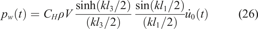
Here, C
H
is the horizontal force coefficient, ρ is the density of water, V is the volume of the rectangular block (=l1l2l3), k is the wave number and
The horizontal water particle acceleration is provided by the following equation (Chakrabarti, 2005).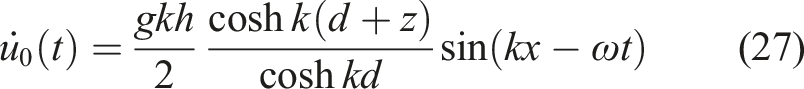
Here, h is wave height, x is the horizontal coordinate of the point at which 

As the surge motion of the FPSO is under study, here, l1 is equal to L, l2 is equal to B and l3 is equal to D. The sea state considered in this study is obtained from field measurements in the North Sea (Christou and Ewans, 2014). The wave height (h) is taken as 6 m and the corresponding wave period (T) is considered as 16 s (0.3927 rad/s). Equations (28) and (29) yield the wavelength and wave number as 399.7 m and is 0.0157 respectively. The force coefficient, C H , is taken as 1.5, which is the recommended value for a rectangular block, provided the diffraction parameter, ka, lies in the range 0 to 5, where k is the wave number and a is the characteristic dimension of the FPSO in the plane of the wave. Here, the characteristic dimension of the FPSO in the plane of the wave (a) is the length (L) of the FPSO, which is equal to 312 m. With the afore-mentioned values k and a, ka is equal to 4.898, which lies in the prescribed range of 0 to 5.
Design and performance of the TMDI system in time domain
As can be observed from Table 2, the natural frequencies of the TMDI are very low, and when compared to the frequency of wave loading, results in a very high ratio of forcing frequency to structural natural frequency. Thus, a high inertia is required to reduce the dynamic response of the structure, which is possible to provide by means of the inerter. In the present study, the values of μ and β are considered as 0.02 and 0.78, respectively (Pietrosanti et al., 2017). This leads to the overall inertance to be 2.338×10⁸ kg. As a demonstration, this can be realized by taking the values of the ratios of r
f
/r
fp
and r
q
/r
qp
as three and 4, respectively, assigning m
f
a value of 10 kg, and the use of six gears (see equation (2)). Next, the optimal values of tuning ratio between the damper frequency and wave frequency, and the damping ratio of the TMDI are investigated. This is carried out with following objective
Initially, the oil tanks are considered to be in the full condition. The FPSO displacement is obtained by solving the equations of motion of the FPSO-TMDI system by using the fourth-order Runge–Kutta method. In this scheme, the derivative is computed four times in every step, once at the starting point, twice at the intermediate points and once at the final point of a time step. By considering a weighted average of these derivatives and the function values at the starting point, the final function value is determined at the conclusion of the time step. This scheme exhibits high accuracy and robustness (Press et al., 1992). The optimization study is conducted by using Genetic Algorithm (GA), vide the toolbox provided in MATLAB (R2016a). GA has earlier been used to optimize inerter parameters, such as in the recent work by Luo et al. (2023), in which GA has been applied for the multi-objective optimization design of different negative-stiffness dampers, namely, negative-stiffness viscous damper (NSVD), negative-stiffness viscoelastic damper (NSVeD), and negative-stiffness inertoviscous damper (NSiVD), individually incorporated into a base-isolated building. In the current study, the parameters used to characterize GA are: (i) Population size – 50 individuals; (ii) Fitness scaling function – Rank; (iii) Crossover function scattered with a crossover fraction – 0.8; (iv) Stopping criteria – 200 (=100*number of variables) generations or function tolerance of 10-6.
Comparison of the Peak displacement (in m) of Uncontrolled FPSO and Controlled FPSO-TMDI With Optimal tuning Ratio and Different TMDI damping Ratios.
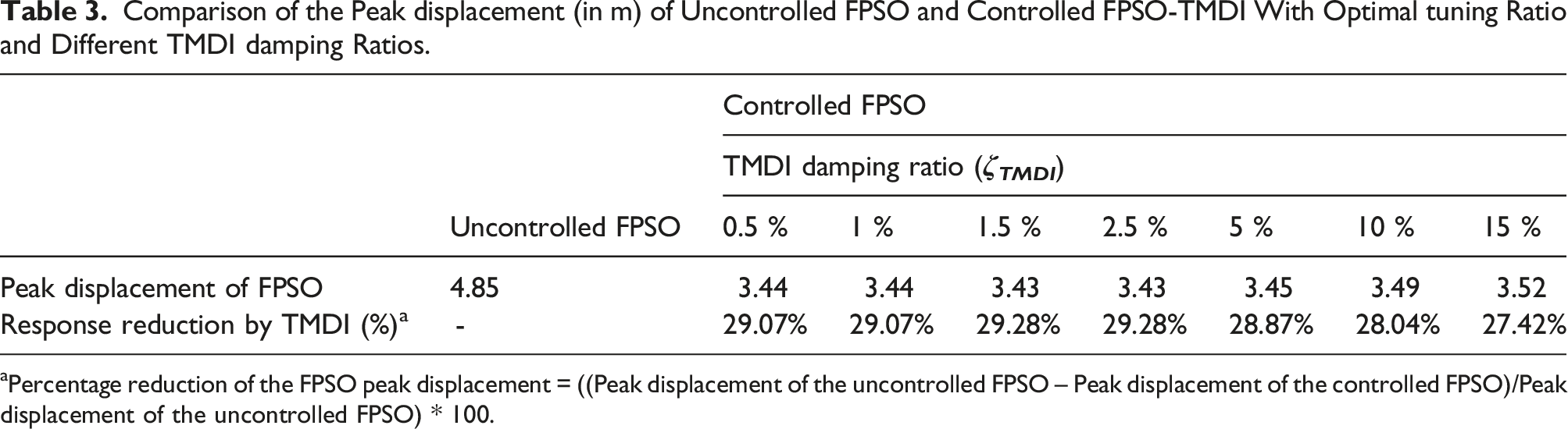
aPercentage reduction of the FPSO peak displacement = ((Peak displacement of the uncontrolled FPSO – Peak displacement of the controlled FPSO)/Peak displacement of the uncontrolled FPSO) * 100.
Comparison of the Peak displacement (in m) of Uncontrolled and Controlled FPSO and Corresponding Response Reductions (υ = 1, ζ TMDI = 1.5%) for Different Fill Condition of Cargo Tanks, by TMDI and Conventional TMD
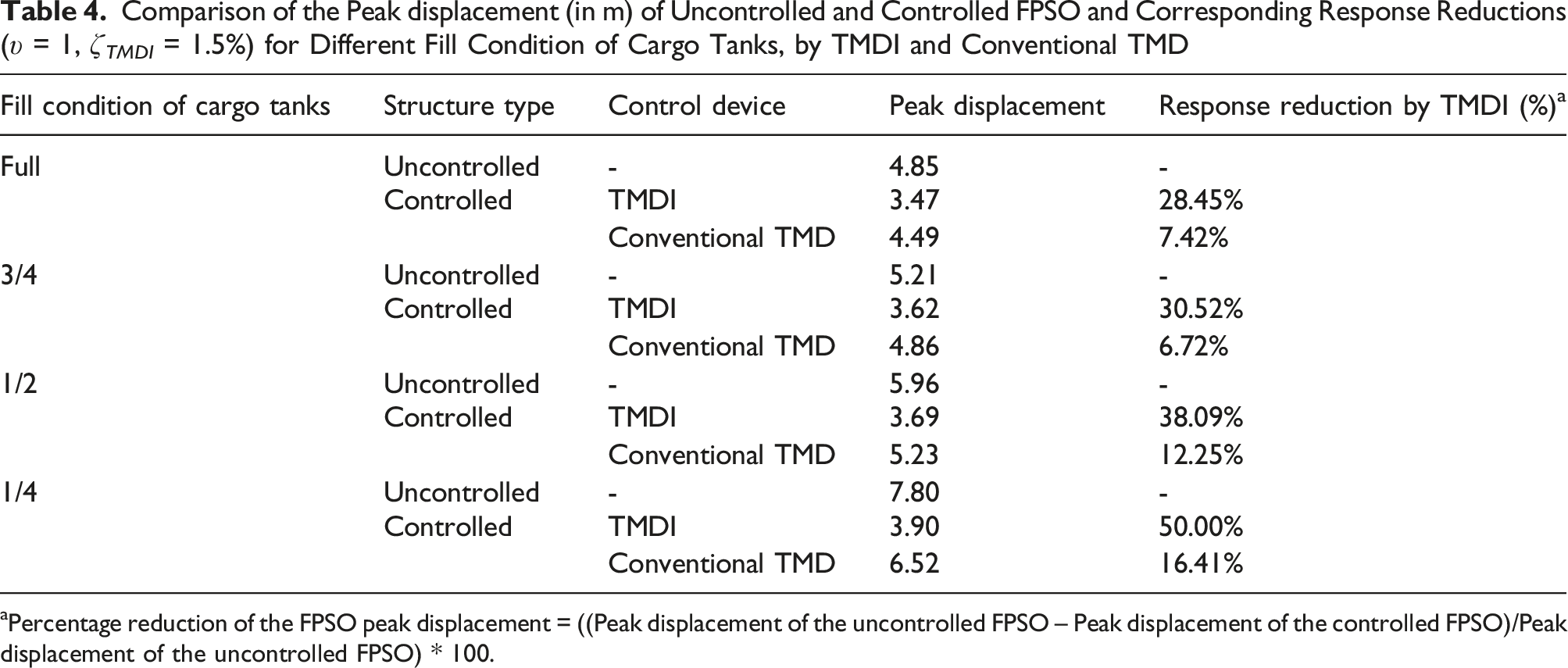
aPercentage reduction of the FPSO peak displacement = ((Peak displacement of the uncontrolled FPSO – Peak displacement of the controlled FPSO)/Peak displacement of the uncontrolled FPSO) * 100.
The displacement time histories of the uncontrolled and controlled surge motion of the FPSO considering tuning ratio unity for the different fill conditions of the cargo tanks are presented in Figure 4(a)–(d). The nature of the uncontrolled time histories is typical of a highly flexible structure subjected to forced harmonic loading that is far stiffer compared to the structural frequency. The oscillations try to take place in the forcing frequency, with rapid fluctuations. The time histories of the controlled structure are far smoother, but with a longer transient phase. The reductions in rms responses are found to be low (around 5%) for all cases, except in the 1/4-fill condition, where it is 21%. The oscillations take place in the fundamental structural frequency. The displacement time histories of the uncontrolled and controlled FPSO with tuning ratio unity, for (a) full, (b) 3/4-fill, (c) 1/2-fill and (d) 1/4-fill condition.
It is also interesting to examine the effect of the TMDI on the response of the sloshing mass in the FPSO-TMDI system. It is seen that the displacement response of the sloshing mass in the model of Figure 3(b) is also reduced with the incorporation of the TMDI with the parameters as used for Table 4. The reductions in peak sloshing displacement for full, 3/4-fill, 1/2-fill and 1/4-fill tank conditions are obtained as 29.66%, 36.52%, 54.53% and 50.00%, respectively. The reduction in sloshing displacement increases the stability of the FPSO and helps to check the spilling of oil on the deck of the FPSO. However, it is to be noted that while this study offers an understanding of the decrease in the movement of the sloshing liquid, it does not precisely depict the motion of fluid within the hull of the FPSO. The TMD displacement for all the mass conditions ranges between 4.18 m to 4.43 m.
Design and performance of the TMDI system in frequency domain
As the FPSOs have a large time period, the transient phase of the motion is present for a significant period of time (1300 s to 1500 s) when the FPSO is subjected to the regular wave loading. The foregoing section has indicated that the peak response of the FPSO can be significantly minimized by means of the TMDI, however, the transient phase remains a prolonged one and rms response reductions are low. This is a source of discomfort for the crew members working on the FPSO and can lead to other serviceability issues. Thus, the reduction in rms response is also important to rapidly achieve small amplitude steady state vibrations. With this objective, a study is carried out on the optimization of the H2-norm of the FRF of the surge motion of the FPSO, 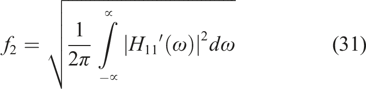
This optimization procedure possesses enhanced robustness and generality, as it does not consider the input wave force. The optimization is carried out by using GA vide the toolbox provided in MATLAB (R2016a). Here, the values of μ and β are kept fixed and are the same as in section 5.3, and the design parameters of the TMDI are its tuning and damping ratios.
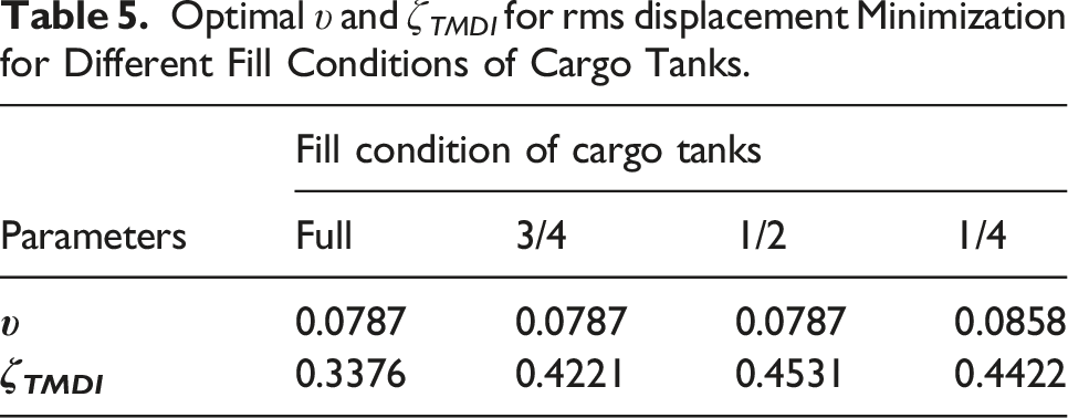
Optimal υ and ζ TMDI for rms displacement Minimization for Different Fill Conditions of Cargo Tanks.
The displacement FRFs of the uncontrolled (H11(ω)) and the controlled Displacement FRFs of the uncontrolled (H11(ω)) and controlled 
Comparison of the rms and Peak displacement (in m) of Uncontrolled and Controlled FPSO With Optimal tuning Parameters for rms displacement Minimization, Under Different Fill Condition of Cargo Tanks.

aPercentage reduction of the FPSO displacement = ((Displacement of the uncontrolled FPSO – Displacement of the controlled FPSO)/Displacement of the uncontrolled FPSO) * 100.
The displacement time histories of the uncontrolled and controlled FPSO with the optimal tuning and damping parameters of the TMDI for the four different fill conditions of the cargo tanks as given in Table 6 are presented in Figure 6(a))–(d). Here, (i) to (iv) have the same definition as in Figure 5(a))–(d). It is observed that in comparison to Figure 4(a))–(d), the transient phase of the FPSO displacement has been greatly reduced by the TMDI, and significantly small amplitude steady state vibrations take place. This is due to the TMDI being designed with optimal parameters corresponding to minimization of rms response reduction rather than minimization of peak response reduction. Further, as evinced from Table 6, the performance of the TMDI is comparatively inferior for the 1/4-fill condition of the cargo tanks, which is reflected in the time histories in Figure 6(d), wherein the amplitude of the steady state vibration is higher than those in Figure 6(a))–(c) It is also observed that there is negligible difference in the controlled FPSO time histories for the optimal and non-optimally designed TMDI cases. This is because the values of the optimal parameters of the TMDI derived for the different fill conditions are very close, especially for the full to 1/2-fill tank conditions, which again is due to the fundamental frequency of the FPSO being very well-separated from the frequency of the input wave excitation. The displacement time histories of the uncontrolled and controlled FPSO under various fill conditions of cargo tanks, with optimal and non-optimal TMDI parameters.
Conclusion
The FPSO is a highly flexible system and its vibration control under wave loading by a TMD will yield results only with very high mass ratio. As it is not feasible to provide such a large physical mass of the TMD, the present study has investigated an inerter linked to the TMD mass to deliver the required high inertia. The equations of motion and the frequency response functions for the uncontrolled FPSO and controlled FPSO-TMDI systems, modelled as lumped mass systems that include the impulsive and convective liquid motions in the cargo tanks, have been formulated. The effect of different fill conditions of the cargo tanks has been studied. Wave load on the FPSO has been calculated from the Froude-Krylov theory, which has further been modified by a force coefficient to account for the change in the fluid flow due to the presence of the structure. Two distinct optimization studies, using GA, have been conducted on the TMDI parameters, to minimize the peak and rms surge response of the FPSO. The performance of the TMDI in the reduction of the surge displacement response of the structure, with optimal and non-optimal parameters, has been examined. The chief conclusions obtained from the investigation are listed below. Tuning of the mass damper to the input wave frequency, and provision of high inertia by the TMDI, can effectively mitigate the peak surge vibrational response of the FPSO under various fill conditions of the cargo tanks. The reductions in the peak surge displacement range between 28% to 50%. However, the transient phase of the vibrational response remains for a prolonged time, and the rms response reductions are marginal. The optimal value of tuning ratio for peak displacement reduction is close to unity and the optimal TMDI damping ratio is low (around 1.5%). However, the peak displacement of the FPSO is insensitive to the variation of the damping ratio of the TMDI. The minimization of the H2-norm of the FPSO displacement FRF provides optimal υ and ζ
TMDI
that reduces the transient phase of the response and quickly reaches a state of small amplitude steady state vibrations. The reductions in rms response of the FPSO with optimal TMDI parameters for full, 3/4-fill and 1/2-fill cargo tanks are as high as 60%, whereas for 1/4-fill tank, the reduction is around 35%. This is due to the higher amplitude of steady state response of the FPSO for 1/4-fill condition. The corresponding peak response reductions are also appreciable, ranging between 20% to 28% for full to 1/4-fill condition. Hence, it may be a better option to adopt this design of the TMDI, in comparison to that corresponding to minimization of peak response reduction. The optimized values of υ for rms response reductions are much lower than unity, and optimized values of ζ
TMDI
are considerably high as compared to those for peak response reduction. There is little performance sensitivity of the TMDI to minor changes in the optimal tuning and damping parameters, as obtained for various mass conditions of the FPSO. The TMDI also offers a reduction in sloshing displacement of the liquid in the cargo tanks, which increases the stability of the FPSO and helps to prevent oil spillage on the deck of the FPSO.
Overall, it can be concluded from the present study that the incorporation of TMDI with the FPSO holds significant potential in the mitigation of wave-induced surge vibrations of the FPSO. Future research is intended to take care of a more sophisticated modelling of the FPSO and including the effect of a compliant connection of the inerter terminal. The FPSO can be modelled through finite element or as a coupled 6-DOF rigid body, and a global performance assessment of the damper can be carried out under coupled motions of the FPSO, such as coupling between surge and pitch, and surge and yaw.
Footnotes
Declaration of conflicting interests
The author(s) declared no potential conflicts of interest with respect to the research, authorship, and/or publication of this article.
Funding
The author(s) received no financial support for the research, authorship, and/or publication of this article.