
Abstract
Composite slab has extensive application in building industrialization. In this study, a novel composite slab with a joint was proposed, where the precast planks with bent-up rebar are only partially prefabricated along the thickness direction at the joint for cast-in-site pouring of concrete, and the rest is fully prefabricated in the factory. The flexural performance of the composite slab was compared with that of a traditional cast-in-site slab with the same geometric dimensions through four-point bending test. The results demonstrate that the bending performance of the composite slab, including cracking load, yield load, and ultimate load, is basically consistent with that of the cast-in-site slab, and can meet the engineering requirements. Based on experimental results, numerical research was conducted on the composite slabs. The effects of slab thickness, diameter of steel bar, concrete strength of precast plank, and slab span on the flexural behavior of composite slab were investigated. The numerical results show that the cracking load, yield load, and load corresponding to the deflection limit of the specimen increase with the increase in slab thickness and decrease with the increase in slab span. Increasing the steel bar diameter can increase the load corresponding to the deflection limit and yield load, while the effect on the cracking load is almost negligible. The concrete strength of precast plank has no significant effect on the flexural behavior of the composite slab.
Introduction
Precast concrete (PC) composite slabs, as a precast structural concrete element, have been widely used in large residential and commercial buildings due to their guaranteed quality, ease of installation, and reduced construction times. The composite slab is composed of a bottom precast plank and a cast-in-situ concrete topping, which combines the benefits of cast-in-situ slab and fully prefabricated slab, and it has undergone extensive research (Elamary et al., 2017; Hou et al., 2016; Ibrahim et al., 2016; Lam et al., 2019; Xiao et al., 2018; Machado, 2019).
The latticed girder composite slab (LGCS) is currently the most common PC composite slabs in China formed by cast-in-site topping with concrete on the precast RC plank with lattice girder. The lattice girder can not only improve the stiffness of the precast plank but also improve the bonding performance between the precast plank and the cast-in-situ concrete topping (Cao et al., 2020; Wang et al., 2016; Xie et al., 2020). However, the thickness and size of the LGSS used in China are relatively small, and the improvement of precast plank stiffness by the lattice girder is limited (Nie et al., 2021; Zhang et al., 2023). During the construction process, it is difficult for precast planks alone to withstand various construction loads, often requiring the installation of a large number of vertical supports, which reduces construction efficiency. Thus, it is necessary to propose a new type of composite slab that requires less support or no support.
Precast plank is a crucial component of composite slab, and its configuration details are the key to determining the mechanical properties of composite slab. In general, the maximum geometric size of a precast plank is limited by transportation capacity and the allowable deflection during construction (Yun et al., 2022). As a result, a reasonable construction joint needs to be adopted to connect pieces of precast plank to form floors in the building structures. Particularly for two-way slabs, the ability of the joint to transfer internal force determines the mechanical properties of the slab. Therefore, when designing a novel composite slab, the reasonable design of the joint should be considered first. Figure 1 depicts the three most common types of joint configurations of LGCS (T/CECS 715-2020, 2020). The joints shown in Figure 1(a) have similar flexural performance to cast-in-situ structures and exhibit a capacity for two-way force transmission. Although the joint shown in Figure 1(b) has certain two-way force transmission performance, the interface between the precast plank and cast-in-situ concrete topping was prone to tearing. For the joints shown in Figure 1(c), it cannot transmit internal forces perpendicular to the joint, so it is applied to one-way composite slabs. In addition, some scholars have proposed some novel joints for composite slabs and evaluated their mechanical properties through experiments. Kim et al. (2015) proposed a loop joint suitable for the composite decks. It found that the bearing capacity and crack resistance of the composite decks connected by this joint can meet the requirements. Chen et al. (2022) developed a novel composite slab with bend-up rebar and conducted flexural bearing capacity research on it, which showed that the presence of bent-up rebar improved the bonding performance of the interface and enhanced the anchorage effectiveness of the lap-splice rebar. Liu et al. (2021) carried out the bending tests on the LGSS connected by joint without gap. The results indicated that the lattice girder within the lapping zone could effectively prevent significant tearing, as was obtained in similar tests by Stehle et al. (2011). Ding et al. (2015) proposed a composite slab with a new type of joint that strengthens the connection between the cast-in-situ area and the bent-up rebar through a multifunctional limiter. The results showed that the flexural behaviors of the composite slab were comparable to those of the cast-in-situ slab. As described above, the designed joint should be able to effectively and continuously transmit the internal force between two precast planks and avoid tearing of the interface. Three types of joints for LGCS.
On the other hand, to achieve unsupported construction of composite slab, it is necessary to increase the stiffness of the precast plank. At present, the method of setting ribs (Ayoub et al., 2021; Zhang et al., 2015), steel tube (Hou et al., 2017; Zhang et al., 2023), or special materials (Wang et al., 2021; Yi et al., 2021) on the top surface of precast plank is commonly used to increases the stiffness of precast plank. However, the amount of cast-in-site concrete for composite slabs using above construction method is still relatively large, and the production of precast plank templates is cumbersome. To achieve unsupported construction and reducing on-site concrete pouring volume, this paper proposed a new type of composite slab with a joint, as shown in Figure 2. The slab of precast plank has removed the lattice girder and only poured concrete at the joints around the edges, the rest of the positions are prefabricated as a whole. A tough surface was designed on the top surface of the precast plank at the joint. The end of the longitudinal steel bars at the bottom of the precast plank was bent up, creating a “bent-up end”. The transverse rebar was mounted vertically above the longitudinal rebar of the precast plank, and concrete was poured at the connection between two precast planks to form the novel composite slab with a joint. In industrial construction, compared to LGCs, the partial prefabrication at the joint of the new composite slab increases the amount of template production but longitudinal steel bars are used instead of lattice girder, greatly reducing the amount of steel used and lowering production costs. To investigate the flexural behavior of novel precast slabs with a joint, two precast planks with a width of 960 mm were connected as formwork of the concrete topping. Flexural tests were carried out on a cast-in-situ slab and a composite slab with a joint to compare and analyze the deformation mode, load-midspan deflection curve, and strain development. In the numerical analysis, the finite element models (FEMs) of slab was established and the reliability of the FEM was verified. The effects of the slab thickness, the concrete strength of the precast plank, the diameter of the longitudinal steel bar, and the slab span on the mechanical performances of the specimens were investigated numerically. This study can provide a basis for the design of the novel composite slab Configuration of novel composite slab with a joint.
Experimental investigation
Material property
The average axial compressive strengths for both the precast plank and cast-in-situ concrete topping were 38.5 MPa and 46.7 MPa, which were obtained from the standard experiment of six cubes with a side length of 150 mm (GB/Y 50,081-2010, 2010). The Young’s modules, yield stress, and ultimate stress of 8 mm diameter steel bars were obtained through tensile coupon tests (GB/T 228.1-2010, 2010), with values of 19.6 GPa, 524 MPa, and 688 MPa, respectively.
Specimen design and production
Two full-scale specimens were designed referring to the specifications for concrete structure design (GB 50,010-2010, 2010) including a traditional cast-in-situ slab (CS) and a precast composite slab with a joint (PS). The geometrical dimensions and steel bar arrangements of the traditional cast-in-situ slab are displayed in Figure 3. For the composite slab with a joint, it consists of two identical precast planks and a cast-in-situ concrete topping. Figure 4 shows the design geometric dimensions and steel bar arrangements of the precast plank. Two layers of rebar mesh were mounted in precast planks, and these bars have a diameter of 8 mm. The bottom bent-up rebar extends 261 mm beyond the side edge of the precast plank with a bend-up angle of 135°. The distance between the top longitudinal steel rebar and the same side edge of the precast plank was also 261 mm. The concrete cover thickness of the longitudinal steel bar was 23 mm. Geometric dimensions and steel bar arrangements of the traditional cast in situ slab. Geometric dimensions and steel bar arrangements of the precast plank.

The composite slab with a joint was divided into two pours. As depicted in Figure 5, after precast planks were poured and installed in place, the longitudinal steel bars were bundled and connected. Transverse steel bars were placed vertically above the longitudinal steel bars. Finally, the cast-in-situ concrete toppings were poured to form a novel composite slab with a joints. The length, width, and thickness of the composite slab with a joint were 3980 mm, 960 mm, and 120 mm, respectively, which are consistent with the cast in situ slab. Configurations of the novel composite slab.
Testing setup, instrumentation, and loading protocol
The testing setup is presented in Figure 6. All specimens were simply supported with a fixed hinge device at one end and a sliding hinge device at the other end. A monotonic loading was applied by the jack. Preloading was conducted before the test. Three cycles of preloading up to about 2.0 kN were performed to check the experimental device and instruments. After the end of preloading, the loading applied increased by 2 kN increments with a loading speed of 0.1 kN/s. when the slab cracks, the load increment of each stage was changed to 4 kN. Stop loading until one of the following conditions was satisfied (GB/T 50,152-2012, 2012): 1) The maximum crack width reaches 1.5 mm. 2) The bending deflection of the slab reaches 1/50 times the span of the slab. 3) The strain value of the steel bar subjected to tensile force reaches 0.01. 4) The compressive strain of the concrete reaches 0.0033 or the concrete is crushed. Testing setup.
The linear variable displacement transducer was installed in the midspan, as shown in Figure 6. In order to get the strain development characteristics of longitudinal steel rebar and concrete during the test, four strain gauges were pasted on the longitudinal steel rebar at the mid-span (#1 and #2) and the longitudinal steel rebar at the interface between the precast and cast in situ concrete topping (#3 and #4). In addition, five strain gauges was attached to the concrete on the midspan of the side surface, and another strain gauge was attached to the concrete on the midspan of the top surface.
Test results
Deformation mode
Figures 7 and 8 depict the typical failure modes and crack development patterns of the specimens. These two slabs have similar failure characteristics. Taking the specimen PS as an example, when the load reached 9 kN, initial transverse cracking occurred on the interface between the precast plank and cast-in-situ concrete topping at the bottom of the slab. With an increase in the applied load, several other parallel cracks appeared at the bottom of the slab and gradually extend to the side surfaces of the slab. Finally, the crack width on the bottom interface reaches 1.5 mm and the specimen fails with the applied load of 28 kN. The precast plank works well with the concrete topping in the loading process. The crack development pattern of the cast-in-situ slab specimen is similar to that of the composite slab, but the initial crack location and the widest crack location were at the midspan of the bottom surface. Overall, both cast-in-situ slab and composite slab exhibited typical flexural ductility failures. Failure mode and bottom crack pattern. Crack development and distributions of specimens in the bottom surface.

Load - deformation behavior
The load-midspan deflection relationship curves of specimens are presented in Figure 9. The curves of the specimens exhibit similar development trends. The whole loading process can be separated into three stages: I) The stage of concrete not cracking, where the curve shows a linear relationship at this time. II) The stage from concrete cracking to rebar yield, where the bending stiffness slightly decreases, and the curve shows an approximate linear relationship between load and displacement. III) The stage where the steel bars begin to yield until the specimen fails, where the tensile steel bar here reaches its yield strength and the bending stiffness of the specimen rapidly decreases, with the curve approximating a straight line. Comparison of load-midspan deflection curves.
Experimental Values of Representative Point.

Strain response of the steel bars and concrete
Figure 10 shows the load-strain relationship curves of the steel bars at the midspan section and the section where the bottom interface is located. The layouts of the strain gauge are depicted in Figures 3 and 5. According to the results of the steel bar material properties test, the steel bar yields when the strain reaches 2670με. As shown in Figure 10, the yield position of the steel bars of the composite slab and the cast-in-situ were different. For the cast in situ slab, the steel bars at the bottom of the mid-span slab yield, while for the composite slab, the steel bars at the interface of the bottom of the slab yield. This is attributed to the overlapping of the steel bars on the bottom surface of the composite slab, where the two steel bars jointly bear the bending moment. Longitudinal strain of steel bar.
Figure 11(a) depicts the load-strain curves of five strain measuring points arranged along the thickness direction of the slab at the midspan side surface. The layout of measurement points is shown in Figure 6, with measurement points a, b, c, d, and e from the top to the bottom of slab. As shown in Figure 11, Compared to cast-in-place slabs, the strain development rate near the bottom of the composite slab is slower, indicating that the composite slab has better crack resistance at the mid-span. Figure 11(c) compares the strain development of the cast in situ slab and the composite slab at the midspan of the top surface. As presented in Figure 11(c), the top concrete of the slab has been in a compressive state throughout the entire loading process, and the strain development speed of the cast-in-place slab is significantly faster than that of the composite slab. Longitudinal strain of concrete.
Finite element analysis
In order to further understand the flexural behavior of the novel composite slab, a FEA model was constructed in this section by using the ABAQUS/Standard module (ABAQUS/CAE, 2014). The accuracy of the FE models was verified by comparing the results acquired from the FE analysis with the experimental data.
Material model
For concrete members, ABAQUS provides two constitutive models, the concrete smeared cracking model and the concrete plastic damage (CDP) model, which are used to describe the characteristics of concrete materials (Hibbitt et al., 1998; Birtel et al., 2006). Some studies have shown that the two constitutive modes have similar numerical results for concrete flexural members under monotonic loads, and both can accurately simulate the bending performance of the members. Zhang et al. (2013) conducted numerical analysis on PK prestressed concrete composite slabs and found that the CDP model is more suitable for simulating the mechanical performance of composite slabs under static load. Based on the above research results, the CDP model provided by ABAQUS was adopted in this numerical simulation for the concrete in the precast plank and the concrete topping.
The CDP model in ABAUQS requires plasticity parameters and uniaxial stress-strain behavior of the concrete inputs to define it. The plastic parameters include dilation angle (

According to the damage law provided by GB50010-2012, the tensile damage parameter dt of concrete is given as:


Under uniaxial compression, the compressive damage parameter dc is determined as:


The bilinear hardening model was adopted to depict the uniaxial stress-strain relationship curves of steel bars as shown in Figure 12, where the hardening modulus Uniaxial stress-strain curve for steel bar.
Interaction setting
Related Parameters of Cohesive Model.

Boundary, loading conditions and solution methods
Four steel plates with a thickness of 20-mm were used to model loading plates and hinged supports. The loads and boundary conditions were set on reference points, which were coupled with the surface of loading plates and supports, respectively. The two ends of the finite element model are hinged constraints consistent with the experiment. The support at one end of the slab restrained its translational degrees of freedom, only releasing the z-axis rotational degrees of freedom. The support at the other end of the slab has fixed translational degrees of freedom except for the x-axis direction, and the z-axis rotational degrees of freedom are also released. Target displacements were applied to RP-1 and PR-2 located above the loading plates for loading, respectively, as shown in Figure 13. The Newton-Raphson algorithm was selected to solve the equations. (Behrooz et al., 2020). FE model of the novel composite slab.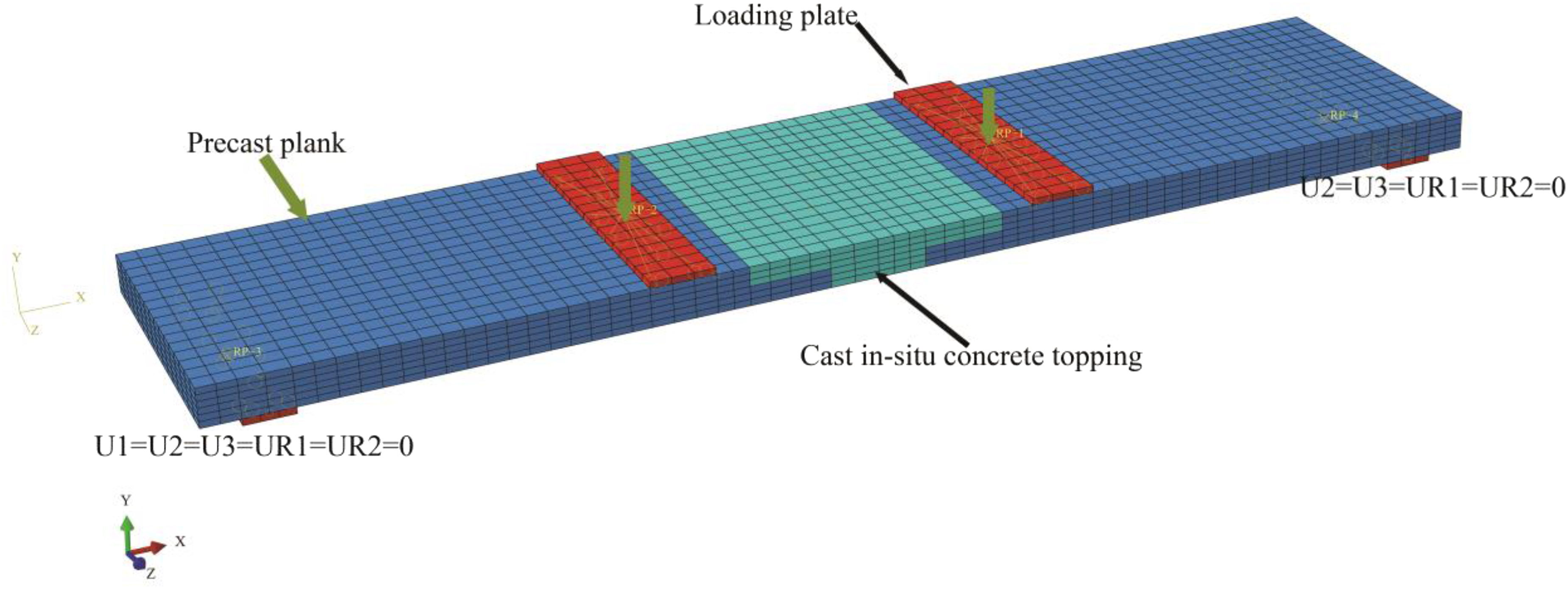
Mesh generation
In this study, Eight-node 3D hexahedral (brick) elements with reduced integration were adopted to simulate the concrete, support, and loading plates, which has good computational efficiency (Nascimbene et al., 2014; Nascimbene et al., 2022). The steel rebar was modeled by two-node linear truss element (T3D2). In addition, mesh density not only affects the efficiency of numerical simulation, but also affects the accuracy of numerical simulation. To achieve a balance between the calculation efficiency and calculation time, the suitable mesh size of the specimen was identified by mesh sensitivity studies. Taking specimen PS as an example, the load-midspan deflection curves obtain from numerical simulation under different mesh sizes is shown in Figure 14. As shown in Figure 14, for models with six and eight elements arranged along the height direction of the slab, compared to models with four elements arranged along the height direction, they can better simulate the mechanical properties of the composite slab after the steel bars yield. When the grid size increases from six along the height direction to eight, the load displacement curves of the two models are basically the same. Therefore, for the finite element model in this study, six elements are arranged in the height direction with each mesh size of 60 mm × 60 mm × 20 mm, as show in Figure 13. Mesh sensitivity analysis results of specimen PS.
Verification of FEM
To validate the accuracy of FEM, the load-midspan deflection and crack distribution characteristics acquired from the FEM were compared with those from the test. Figure 15 displays the comparison of the load-midspan deflection curves of the FE model and tested specimens. The general trend of the load-midspan curves obtained from the FE analysis was in good agreement with the experimental results. The representative points were also compared in Table 1. As shown in Table 1, for the composite slab, the errors of Pcr, Pl/200 and Py obtained from finite element analysis and testing are 11.3%, 4.4%, and 11.3%, respectively. The load value obtained from finite element analysis is higher than the experiment, which is attributed to that the finite element does not take into account the bond slip between steel bars and concrete. In summary, the load-midspan deflection curves derived from the FEM coincided with those from test results pretty well, demonstrating the FEM’s correctness. Comparisons of load-midspan deflection curves for the slabs from experimental and numerical model.
Select the tensile damage cloud map of the composite slab as the basis for distinguishing the development of concrete cracks, as displayed in Figure 16. The location of the first crack at the bottom of the slab in the numerical model remains consistent with the experimental results, both of which are cracks on the bottom interface of the precast plank and cast-in-situ concrete topping, as shown in Figure 16(a). After the loading is completed, the distribution of tensile damage at the bottom surface of the slab in the numerical model is basically consistent with the crack development observed in the experiment. The crack development is mainly in the pure bending section between the two loading points. This also indicates that the numerical analysis model and loading method settings used in this loading are in good agreement with the experiments. The concrete tensile damage factor at the bottom surface of specimen SS-1.
Parametric study
Referring to the validated EF modeling technique of specimen CS-1, the parametric study was carried out to investigate the effect of configuration parameters such as slab thickness, the strength of precast plank concrete, the diameter of steel bar, and slab span on the mechanical behavior of composite slab with a joint. Considering that it is difficult to accurately obtain the width of concrete cracks through finite element simulation, the failure load values in the representative values of flexural performance of the specimen will not be analyzed in this section.
Effect of slab thickness
To study the effect of slab thickness on the flexural behavior of composite slabs, finite element analysis was conducted on composite slabs with thicknesses of 100 mm, 120 mm, and 130 mm, respectively. The comparison results are depicted in Figure 17, and Table 3. As shown in Figure 17 and Table 3, the characteristic loads, Pcr, Pl/200, and Py all significantly increase with the increase of slab thickness. In addition, it can be seen from Figure 4 that increasing the slab thickness can also improve the bending stiffness of the composite slab. Overall, increasing the slab thickness can effectively improve the bending performance of composite slabs. In practical engineering applications, factors such as economy and efficiency should be comprehensively considered to reasonably select the thickness of the composite slab. Load-midspan deflection curves of composite slabs with different slab thickness. Numerical Values of the Representative Points for composite Slab With Different Thickness.

Effect of longitudinal steel bar diameter
To study the effect of longitudinal steel bar diameter on the flexural behavior of composite slabs, finite element analysis was conducted on composite slabs with steel bar diameters of 8 mm, 10 mm, and 12 mm, respectively. The comparison results are depicted in Figure 18, and Table 4. As shown in Figure 17 and Table 4, there is no significant difference in the slope of the load-midspan deflection curves of all specimens before reaching the cracking load for all composite slabs, indicating that diameter of steel bars has a negligible effect on the initial stiffness and cracking load. For the load corresponding to the deflection limit, the composite slab with a steel bar diameter of 12 mm has increased by 41% and 87.9% compared to the composite slab with a diameter of 8 mm and 10 mm, respectively. In addition, the yield load significantly increases with the increase of steel bar diameter. Load-midspan deflection curves of composite slab with different steel bar diameter. Numerical Values of the Representative Points for composite Slab With Different longitudinal Steel Diameter.

Effect of precast plank concrete strength
The effect of precast plank concrete strength on the flexural behavior of composite slabs was studied through the comparison of different composite slabs with precast plank concrete strength grades of C30, C40, and C50, respectively. The comparison results are shown in Figure 19, and Table 5. As depicted in Figure 19 and Table 5, the load-midspan deflection curves of the three specimens are basically consistent until the load reaches the yield load, and then as the load increases, the load-midspan deflection curve of the specimen with C40 strength grade is slightly higher than that of the specimens with C20 and C40. Overall, increasing the strength of precast bottom slab concrete has little effect on the bending performance of the composite slab. Load-midspan deflection curves of composite slab with different precast plank concrete strength. Numerical Values of the Representative Points for composite Slab With Different Concrete Strength of precast Plank.

Effect of composite slab span
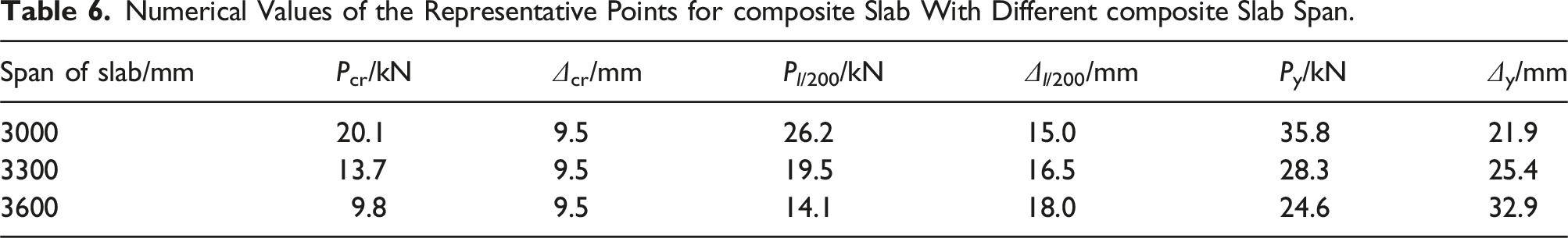
The effect of span on the flexural behavior of composite slabs was studied through the comparison of different composite slabs with spans of 3000 mm, 3300 mm, and 3600 mm, respectively. The comparison results are depicted in Figure 20 and Table 6. As shown in Figure 20 and Table 6, the bending performance of the composite slab decreases with the increase of span. The cracking load, yield load, and deflection limit load of specimens with a span of 3600 mm were 28.5%, 27.7% and 13.1% lower than that of specimens with a span of 3300 mm, respectively. The cracking load, yield load, and deflection limit load of the specimens with a span of 3300 mm were 19.39%, 25.6% and 20.9% lower than that of the specimens with a span of 3000 mm, respectively. The results indicate that the span of the slab has a significant effect on the flexural performance of composite slabs. Load-midspan deflection curves of the composite slab with different span. Numerical Values of the Representative Points for composite Slab With Different composite Slab Span.
Conclusions
The flexural behavior of the novel composite slab was investigated through tests and numerical studies. The main conclusions were obtained: (1) The flexural behaviors of the novel composite slab are similar to those of the cast-in-situ RC slab, both exhibiting ductile failure, that is, the crack width at the bottom of the slab reaches 1.5 mm according the GB/T 50,152-2012, 2012. (2) During the loading process, there was no significant tearing on the interface between the precast plank and cast-in-situ concrete topping, indicating that for this new type of composite slab with a joint, manual roughening to form a concave and convex surface of no less than 4 mm can ensure the bonding performance of the interface. (3) The cohesive model can accurately simulate the mechanical behavior between the precast plank and cast-in-situ concrete topping. (4) Adding diameter of longitudinal steel bars tends can significantly increase the yield load and the load corresponding to deflection limit but not help increase cracking resistance of this novel composite slab. (5) The concrete strength of precast plank when varying between C30 and C50 has a negligible impact on the bending performance of this novel composite slab. (6) The thickness and span of slabs have a great influence on the flexural performance of this novel composite slabs. The critical bending resistances of the composite slab, including cracking load, load corresponding to the deflection limit, and yield load, increase with the increase of thickness and decrease with the increase of span.
Footnotes
Declaration of conflicting interests
The author(s) declared no potential conflicts of interest with respect to the research, authorship, and/or publication of this article.
Funding
The author(s) disclosed receipt of the following financial support for the research, authorship, and/or publication of this article: This work was funded by the Houzhou City Science and Technology Plan Project (2021ZD2029).