



Abstract
This study investigated the effectiveness of carbon fibre-reinforced polymer (CFRP) materials in strengthening the diagonal tension members of steel-truss bridges. Monotonic tensile and cyclic loading tests were performed on CFRP-strengthened specimens with variations in the CFRP-bonding range on the flanges. This study focused on the strengthening methods A and B, which were proposed to address insufficient CFRP anchoring near gusset plates by bonding CFRP sheets to both sides of the flanges of the diagonal tension members. The results of the monotonic tensile loading tests indicated a significant increase in tensile stiffness and substantial improvements in yield strength (27%) and ultimate load-bearing capacity (51%) when the strengthening methods A and B were employed. Delamination of the bonded CFRP sheets was effectively delayed, occurring only after the steel yielded, owing to the use of a ductile adhesive (polyurea putty). On the other hand, the cyclic loading tests demonstrated a significant enhancement in the load-bearing capacities (33% for tensile, 32% for compressive) of the strengthened specimens. Moreover, the energy dissipation capacities of the specimens strengthened by methods A and B exhibited linear increases, with 12% and 14% higher values respectively than those of the non-strengthened specimen. Although the stiffnesses (tensile and compressive) of the strengthened specimens decreased in each loading loop, the strengthening methods A and B maintained the stiffness values at approximately 35% higher than those of the non-strengthened specimen.
Keywords
Introduction
Many of the steel bridges in Japan were constructed during an era of rapid economic growth from the 1950s to the 1970s, and those bridges, which are already over 50 years old, are still in use. In addition, after the Great Hanshin–Awaji Earthquake in 1995 (JSCE, 1995), the seismic design specifications (JARA, 1996) for steel bridges were significantly revised. Specifically, the modified seismic-coefficient method in the old specifications (JARA, 1994) was significantly changed by the cross-sectional design method, which uses dynamic response analyses. Therefore, numerous main structural members of steel bridges that were designed according to the old specifications are in a state of insufficient seismic performance. In particular, in steel-truss bridges with relatively long spans, the dimensions of the lower chord members near the ends of the girders and diagonal members at the midspans had been designed with minimum sizes because of the relatively small regular-bending moments and shear forces acting on them. This design has led to a serious problem: based on a dynamic response analysis performed according to the current seismic design specifications (JARA, 1996), diagonal members and lower chord members, which are always under tensile loads, may suffer local and global buckling (JH, 2016). Therefore, seismic strengthening is highly necessary.
Common techniques for strengthening steel structural members comprise using stiffening plates attached to the members by welding or bolts and replacing deteriorated members with new ones. However, these techniques have limitations because they require the involvement of skilled engineers and heavy machinery. Furthermore, they cause degradation of the steel structural members, including cross-sectional reduction from the use of bolts and heat stress from welding. Additionally, attaching stiffening plates along the entire length of steel structural members using bolted connections for seismic strengthening is considerably challenging. Therefore, scientists and structural engineers have been attempting to develop an effective and simpler strengthening method for steel structural members. Numerous studies have demonstrated that carbon fibre-reinforced polymer (CFRP) is a highly effective material for strengthening and repairing steel structures because of its excellent mechanical properties: high elastic modulus (1.2–3 times that of steel), high strength (5–9 times that of steel), low weight (0.2–0.3 times that of steel), corrosion resistance, and ease of creating any shape (Colombi et al., 2003; Kaan et al., 2012; Pham et al., 2018a, 2018b, 2020, 2021, 2022; Silva et al., 2019; Takamori et al., 2021; Yang et al., 2019; Yasuda et al., 2024; Zhao et al., 2023). Furthermore, CFRP can easily be attached to steel structures without heavy equipment, requires less maintenance post-application, and has no impact on dead loads. CFRP has been extensively studied worldwide: in the USA since the 1970s (McCormick, 1972); in Switzerland, Japan (Ueda and Dei, 2005), and China since the 1980s (Ye et al., 2004); and in the UK since the early 1990s (Hollaway, 1993). In particular, Japan has been a pioneer country in the production and application of CFRP materials in civil infrastructures, accounting for approximately 75% of the global fibre market (Ueda and Dei, 2005) for over 20 years.
Various types of CFRP (high-modulus, intermediate-modulus, and high-strength) with different shapes (rods, cables, sheets, plates, and grids) have been extensively studied for repairing and strengthening steel structures, which are subjected to natural disasters, accidents, corrosion, and fatigue (Pham et al., 2018a, 2018b, 2020, 2021a, 2022; Colombi et al., 2003; Kaan et al., 2012; Silva et al., 2019; Takamori et al., 2021; Yang et al., 2019; Zhao et al., 2023). Furthermore, CFRP has been employed to increase the load-bearing capacities of steel structures with modified initial functions (Hattori et al., 2018; Selvaraj and Madhavan, 2019), in which the most common use of CFRP is to improve fatigue and corrosion factors. Steel structural members are generally subjected to tensile, compressive, flexural, shear, and cyclic loads. However, there are no general CFRP-bonding methods for repairing and strengthening damaged steel structures (Abed et al., 2017; Tafsirojjaman et al., 2022; Zhao and Zhang, 2007). Different types of damage and loads require specific CFRP-bonding methods (Abed et al., 2017; Tafsirojjaman et al., 2022; Zhao and Zhang, 2007). For example, wrapping CFRP sheets around box-section and circular steel members subjected to repeated flexural and compressive loads can increase their load-bearing capacity and delay local buckling (Matsumura et al., 2004; Okazaki et al., 2017). With sufficient anchoring length in the longitudinal direction of steel structural members, CFRP-bonding methods can enhance the load-bearing capacity of members subjected to tensile, compressive, and flexural loads (Miyashita and Nagai, 2010; Pham and Miyashita, 2020; Pham et al., 2022). Additionally, numerous previous studies have indicated that the effectiveness of CFRP-based strengthening depends on several parameters: configuration and type of strengthening technique, type of CFRP materials, number and orientation of CFRP materials, and initial imperfections and slenderness of steel structural members (Abed et al., 2017; Nhut and Matsumoto, 2020; Phan et al., 2020; Tafsirojjaman et al., 2022; Zhao and Zhang, 2007). The corrosion level of the steel surface and the geometric shape of steel parts at the strengthened areas also affect strengthening efficiency due to the CFRP-bonding performance (Silva et al., 2019; Yang et al., 2019; Zhao et al., 2023).
Thus far, various studies have investigated the effectiveness of CFRP-based strengthening techniques for steel structural members under axial stresses. These studies focused on the strengthening of the chord members of steel-truss bridges (Miyashita and Nagai, 2010), slender steel braces (Fengky et al., 2022; Gao et al., 2013; Sakurai et al., 2024), and columns of industrial buildings constructed with hollow cross sections (Abu-Sena et al., 2019; Aguilera and Fam, 2013). In particular, the strengthening of the members of I-girder steel bridges, such as ageing and corroded lower flanges, which are subjected to axial stresses, has received significant attention (Afefy et al., 2016; Kumaraguru and Paramasivan, 2021). Moreover, in 2023, Pham et al. (2023) investigated the efficiency of CFRP retrofitting on diagonal members of steel-truss bridges via axial cyclic loading tests. Their report highlights improvements in the load-bearing capacity, stiffness, and ductility of the retrofitted specimens. However, there has been no investigation related to finding an effective solution that addresses insufficient CFRP anchoring near gusset-plate connections, where the presence of numerous bolts makes it challenging to achieve sufficient CFRP anchoring. Therefore, this study proposes CFRP-bonding methods for use near gusset-plate connections to enhance the load-bearing capacities and seismic performance of strengthened diagonal tension members. The proposed CFRP-bonding methods were evaluated via monotonic axial tensile and axial cyclic loading tests on diagonal tension member specimens. Axial tensile loading was intentionally selected for the specimens because, in actual bridges, diagonal tension members experience primarily axial tensile forces. Conversely, axial cyclic loading was implemented to simulate the inertial forces exerted by the slabs of steel-truss bridges acting along the longitudinal axes of bridges during an earthquake. These inertial forces subject diagonal tension members to repeated loading. Thus, diagonal tension members with thin-plate elements experience compressive forces due to the cyclic loading of earthquakes, and their seismic-resistance behaviour is a significant concern.
The loading tests in the study were performed on a total of two non-strengthened specimens and 9 CFRP-strengthened specimens, which were varied in terms of the CFRP-bonding range on the flanges. Monotonic axial tensile loading tests were conducted to evaluate the effectiveness of CFRP in enhancing the load-bearing capacities of strengthened specimens. On the other hand, axial cyclic loading tests were conducted to investigate the seismic behaviour of the specimens after strengthening. Based on the test results, a method for determining the stiffnesses (compressive and tensile) of the strengthened diagonal tension members under cyclic loading was devised.
Experimental overview
Specimen shape
The main truss system of a steel-truss bridge consists of upper chord members, lower chord members, and diagonal members, which are connected using gusset plates. The diagonal members include diagonal compressive and diagonal tension members, corresponding to box- and H-shaped cross sections, respectively. Figure 1 illustrates the gusset-plate connection shape at the end of a diagonal tension member in an actual steel-truss bridge. One-sided friction joints were used to connect between the flanges of the diagonal tension members and the gusset plates via splice and filler plates. This required a significant number of bolts for the gusset-plate connections, which would have posed a major challenge to bonding CFRP sheets to the bolted areas during strengthening. Additionally, the creation of bolt holes in the gusset-plate connections resulted in an increase in flange thickness of more than 3 mm compared with that of the diagonal member (JH, 1981). There was also a distance of more than 100 mm between the cross-sectional change areas of the flanges and the gusset plate (Figure 1) (JH, 1981). Gusset-plate connection.
Considering the characteristics of the actual diagonal tension members described earlier, this study employed dumbbell-shaped specimens, as illustrated in Figure 2. The upper portions of the dumbbell are connections with the gusset plates, whereas the middle section is the diagonal tension member that requires strengthening. The cross-sectional dimensions of the specimens were determined based on the maximum capacity of the testing machine (3000 kN) and the relative thinness of the actual members. The selected dimensions were 250 mm × 8 mm for the flanges and 320 mm × 8 mm for the web. These dimensions resulted in width–thickness ratio parameters (R) (JARA, 2012) before strengthening with 0.79 for the web and 0.92 for the flanges. The specimens in the study were considered as short columns with a potential for local buckling on the web (R = 0.79) and flange (R = 0.92) under cyclic loading tests. Hence, the diagonal tension member was designed to have a height of 1300 mm, resulting in a total specimen height of 2332 mm (Figure 2). The distance from the area where the cross-section of the flanges changed to the gusset plate was maintained at 100 mm, matching that of actual members. Additionally, the part of the diagonal tension member that required strengthening had a height of 1100 mm (Figure 2). The dimensions of the gusset plates were intentionally increased compared to those of the diagonal tension member (henceforth referred to as “the diagonal member”) to prevent early yielding. Consequently, the gusset plates had a thickness of 12 mm and a width of 450 mm. Furthermore, two steel plates, each 16 mm thick, were added at the ends of the specimens to establish connections with the loading equipment. In the strengthened specimens, which had CFRP sheets bonded to the gusset-plate areas, high-strength bolts (M22(F10T)) were added as actual gusset-plate connections. By contrast, for the other specimens, the presence of bolts on the gusset plates was ignored. Shape of non-strengthened specimen.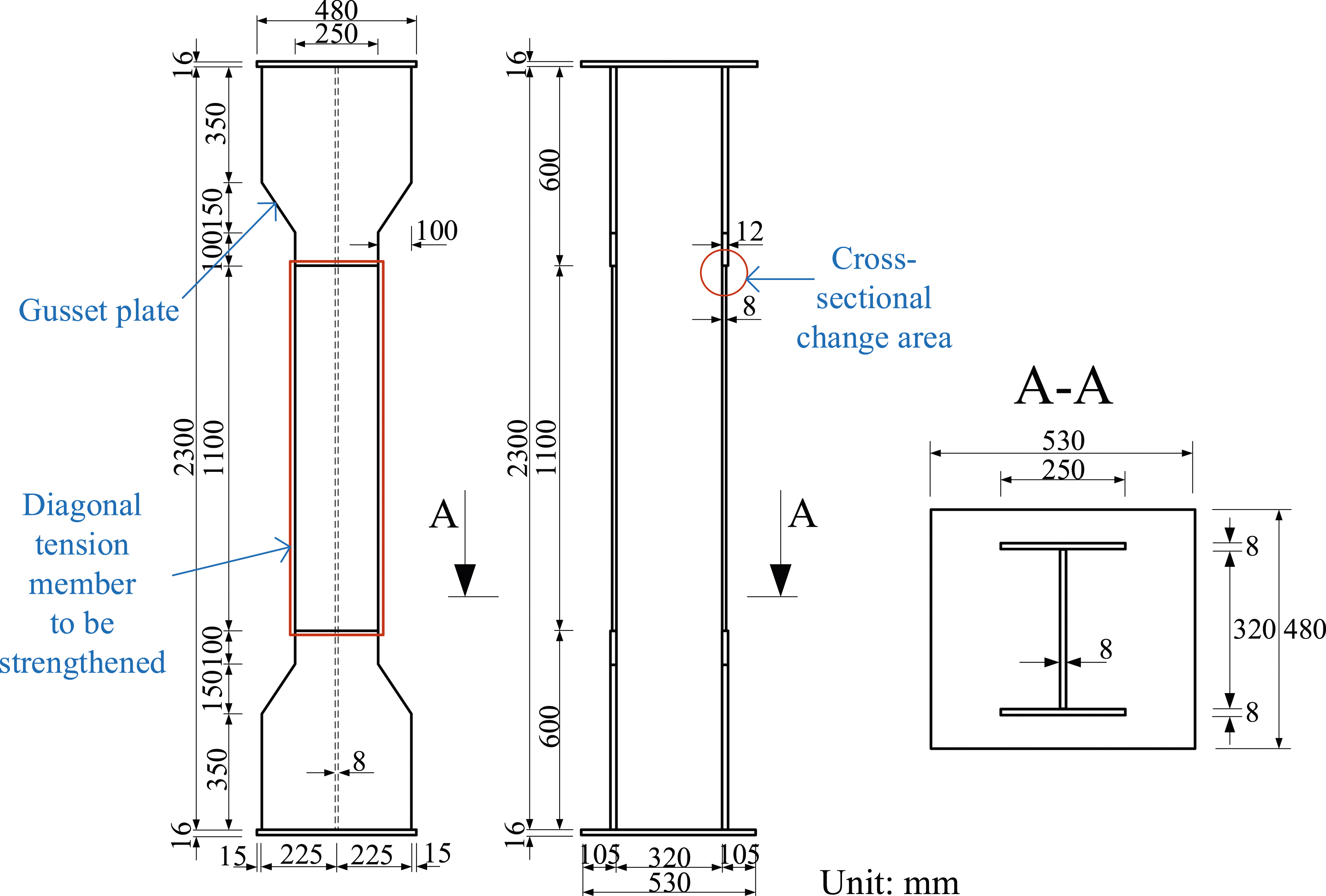
Materials
Material properties.

In CFRP-based strengthening techniques (Nagai et al., 2012; Narmashiri et al., 2012; Zeng et al., 2018), wherein CFRP sheets are directly bonded to steel members using brittle adhesives, CFRP sheets tend to delaminate prematurely under large deformations of steel members such as buckling. Consequently, the full effectiveness of strengthening methods using CFRP sheets is not achieved. Therefore, to enhance the bonding performance between the steel members and the first CFRP layer, a ductile adhesive called polyurea putty was used (Miyashita et al., 2015; NERI, 2015). This adhesive had a low elastic modulus of 72 MPa and a high elongation of 431%. The effectiveness of employing polyurea putty at suppressing the premature delamination of CFRP sheets due to large deformations has been emphasised in numerous studies (Hidekuma et al., 2019; Pham et al., 2021b, 2022). In the strengthened specimens, which had CFRP sheets bonded to the bolted parts, a smoothing agent was used to fill the areas around the bolts. Additionally, a brittle epoxy resin was employed as an adhesive to connect the CFRP sheets to each other.
Experimental parameters
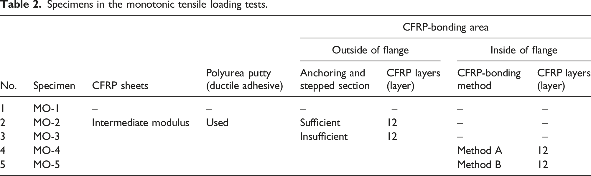
Specimens in the monotonic tensile loading tests.
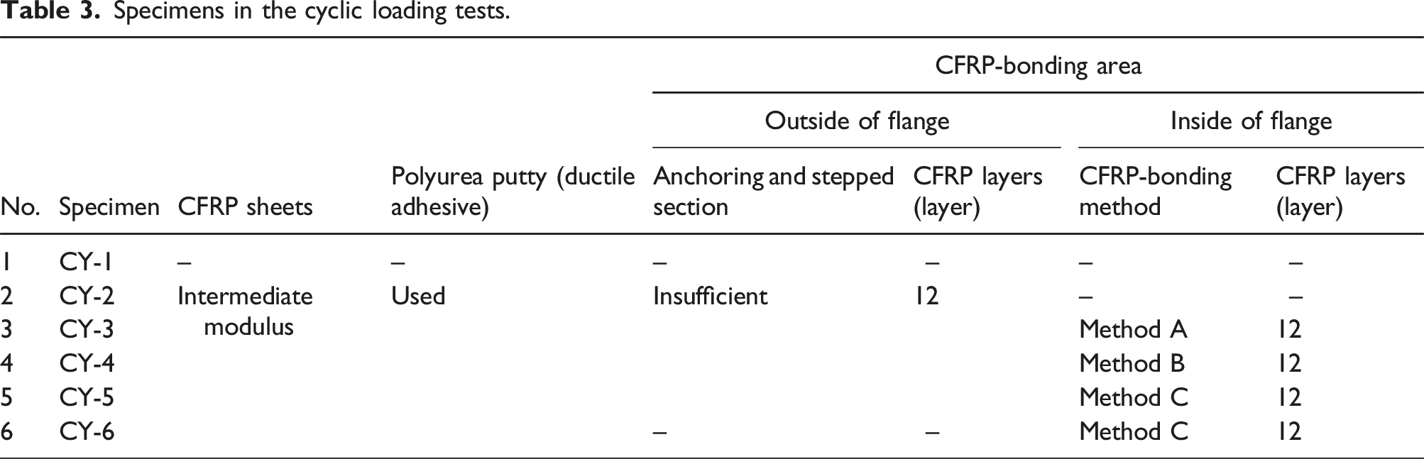
Specimens in the cyclic loading tests.
In actual steel-truss bridges, diagonal members have notched end sections of the web at the gusset-plate connections (Figure 1). In these areas, it is challenging to achieve continuous bonding of CFRP sheets to the webs. Therefore, the focus of this study was to strengthen diagonal members using only CFRP sheets on the flanges. To overcome the local buckling of the plate element, the steel thickness of the flanges of the strengthened specimens must be increased by 3 mm. Thus, after strengthening, the parameter (R) (JARA, 2012) of the width–thickness ratio of the flange was R = 0.68. This value fell within the range in which no reduction in load-bearing capacity occurs owing to local buckling, as specified in the Japan Specifications for Highway Bridges (JARA, 2012). The CFRP layers required to increase the steel thickness by 3 mm were determined using equation (1) (NERI, 2015). This equation implies that, after considering the impact of employing a ductile adhesive material, the combined tensile stiffness of the CFRP layers must exceed the required tensile stiffness of the steel part. According to equation (1), the number of CFRP layers required for strengthening was 12.
The bonding of CFRP sheets along the entire lengths of the diagonal members of steel-truss structures is crucial because the diagonal members experience primarily axial forces and require strengthening. For effective CFRP-based strengthening, constructing sufficient anchoring (200 mm) and stepped sections (25 mm) for each CFRP layer (Figure 3(a) (Miyashita et al., 2015; NERI, 2015)) is essential. This approach ensures the establishment of a full composite cross-section in the strengthened areas, connecting the steel members and CFRP sheets (Miyashita et al., 2015; NERI, 2015). However, in practice, bonding CFRP sheets on the upper side of gusset-plate connections, where numerous bolts are present, to create the required lengths for sufficient CFRP anchoring and stepped sections is a highly challenging task. Therefore, this study proposes methods that involve bonding the CFRP sheets near the gusset plates to address the insufficient CFRP anchoring and validates these methods in monotonic tensile loading tests (Table 2 and Figure 3). In Specimen MO-2, the CFRP sheets were continuously bonded to the outside of the flanges, extending from the diagonal member to the gusset plates (Figure 3(a)). The bonding process included lengths that provided sufficient anchoring and stepped sections of the CFRP sheets. Notably, Specimen MO-2 served as a control specimen for comparing the effectiveness of CFRP-based strengthening with those of other CFRP-bonding methods. In Specimen MO-3, the CFRP sheets were bonded in a limited manner to the edges of the gusset plates without stepped sections, such that there was an insufficient anchoring of 100 mm, as shown in Figure 3(b). To counter this limitation, in Specimens MO-4 and MO-5, part of the CFRP sheets was added to the inside of the flanges, with sufficient anchoring (200 mm) and stepped sections (25 mm) (Figure 3(c) and (d)). On the other hand, under cyclic loading, it was expected that applying CFRP sheets to both sides of the flanges would be highly effective at reducing the eccentric moment in the cross-sectional change areas of the flanges. Specifically, in the bonding method A on Specimen MO-4, the outside of the flanges was overlaid with 12 layers of CFRP sheets, but had an insufficient anchoring of 100 mm. On the inside of the flanges, the CFRP sheets were anchored with sufficient length (200 mm) and stepped sections (25 mm), but only towards the inner direction of the diagonal member. By contrast, the bonding method B on Specimen MO-5 involved bonding the CFRP sheets on the inside of the flanges towards both the inner direction of the diagonal member and the bolted areas. The bonding method B has been deemed feasible for a construction site because only the bolt head was present on the inside of the gusset plates (Figure 1). To supplement the insufficient CFRP anchoring on the outside of the flanges, it was decided that the number of CFRP layers applied on the inside should be similar to that applied on the outside, with 12 layers. CFRP-bonding methods.
In the cyclic loading tests, the CFRP-bonding method used for the control Specimen MO-2 was excluded from this study to optimize the number and configuration of the specimens. Instead, the simplest CFRP-bonding method, characterised by insufficient anchoring solely on the outside of the flanges, was used on Specimen CY-2 (Figure 3(b)). Moreover, Pham et al. (2023) demonstrated that the strengthening effectiveness of the bonding method used on Specimen MO-2 in the compressive direction was approximately the same as that of Specimen CY-2, due to bonding the CFRP sheets to only one side of the flanges. For Specimens CY-3 and CY-4, the same bonding methods A and B used in the monotonic tensile loading tests (Figure 3(c) and (d), respectively) were implemented. Additionally, to investigate the impact of noncontinuous CFRP sections (the bonding methods A and B) bonded in the inner direction of the diagonal member under cyclic loading, another bonding method, C, is proposed. This method involved the continuous bonding of the CFRP sheets on the inside of the flanges and was applied to Specimens CY-5 and CY-6, as shown in Figure 3(e) and (f), respectively. The difference was that in Specimen CY-5, the CFRP sheets were bonded with 12 layers on the outside of the flanges, whereas in Specimen CY-6, there were no CFRP sheets on the outside of the flanges. Consequently, the strengthening level for the diagonal member in Specimen CY-5 was 6 mm, which was twice that for the other cases.
CFRP-bonding process
CFRP sheets were used to reinforce the flanges of the strengthened specimens along the diagonal members’ longitudinal axes. The CFRP-bonding process involved five steps, as illustrated in Figure 4. In the first step, the surfaces of the flanges were prepared by removing rust and old paint using disk sanding. The remaining smears were then cleared using an organic solvent, followed by the immediate application of a primer. Once the primer had dried, a 0.8-mm-thick layer of polyurea putty was applied according to the designed thickness. To ensure an even coverage of the polyurea putty on the flange surfaces, the application was carefully monitored using a weighing scale. After the polyurea putty had dried, the bolted areas were smoothed using an epoxy-type putty. Finally, once the epoxy-type putty had partially hardened, the CFRP sheets were bonded one by one using an epoxy resin. CFRP-bonding process.
Loading method
Figure 5 shows the loading system used for the monotonic tensile and cyclic loading tests. All the specimens were tested using a 3000 kN universal testing machine (Shimadzu, Tokyo, Japan). The specimens were fastened to the loading system using high-tension bolts. A support jig was placed on the lower side, following a link frame positioned on the upper side. Both of these components were designed to function effectively in the linear elastic range of steel. In the monotonic tensile loading tests, the specimens were loaded until they reached the ultimate failure state. For the non-strengthened Specimen MO-1, the loading process was stopped when the strain measured at its central cross-section entered the strain-hardening region of the steel. Loading test condition.
The cyclic loading tests were performed under the same conditions as those for the monotonic tensile loading tests (Figure 5). The relative displacement (δ) of the area 1300 mm apart on the flanges was used to control the applied load, following the loading plan shown in Figure 6. All the specimens were tested until they reached a displacement of 6δ
y
, where δ
y
represents the initial yield relative displacement of the area 1300 mm apart on the flanges of Specimen CY-1 without strengthening. The value of δ
y
was theoretically calculated as 1.8 mm for a variable-cross-section column fixed at both ends. Moreover, the theoretically calculated yield axial force (P
y
) for the non-strengthened specimen was determined to be 1870 kN. Loading plan.
Measurements set up
Figure 7 shows the critical locations for measuring the strain and displacement of the non-strengthened and strengthened specimens. During the loading process, strain gauges with cross- and single-element were attached to the surfaces of the flanges and web. From calculations of the bending strain based on the measured strains on the inner and outer surfaces, the occurrence of local buckling on the web and flanges was confirmed. To measure the deformation of the diagonal members, their vertical displacement on the specimens was considered as the relative displacement within a 1300 mm length range of the flanges, as shown in Figure 7. For this purpose, eight general displacement transducers were installed in these areas. In the analysis of the loading test results, the average relative displacement value in this 1300 mm length range was used to evaluate the load–displacement relationship of the specimens. On the other hand, the out-of-plane displacements at critical locations on the flanges of the strengthened specimens were measured to determine the timing of plastic buckling. Strain gauges were also bonded to the surfaces of the CFRP sheets and steel to evaluate the strain reduction effectiveness on the strengthened diagonal members and to monitor the timing of delamination of the CFRP sheets. Measurements of specimens.
Results and discussion
Monotonic tensile loading cases
Load–displacement relationship
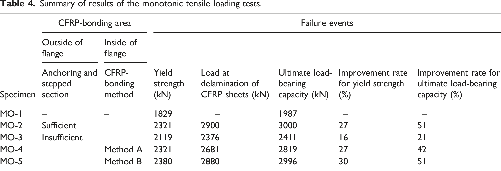
Summary of results of the monotonic tensile loading tests.

Load–displacement relationship in the monotonic tensile loading tests.

Average strain on the diagonal member.
Figure 8 shows that the initial tensile stiffnesses of all the strengthened specimens were greater than that of the non-strengthened Specimen MO-1. The increased initial tensile stiffnesses of the strengthened specimens, after application of the proposed CFRP-bonding methods, are evident in the enlarged view of the load–strain relationship shown in Figure 9(b). The initial tensile stiffness of Specimen MO-3, which had insufficient CFRP anchoring, was improved compared with that of the non-strengthened Specimen MO-1. However, its stiffness was still considerably smaller than that of Specimen MO-2, which was bonded with sufficient CFRP anchoring and stepped sections. On the other hand, through the addition of part of the CFRP sheets to the inside of the flanges, as proposed in the methods A and B, the initial tensile stiffnesses of Specimens MO-4 and MO-5 achieved the same level as that of Specimen MO-2 (Figure 9(b)). This was because bonding CFRP sheets to both sides of the flanges improved stress-transfer effectiveness from the gusset plates to the CFRP sheets. This improvement was necessary to counteract the insufficient CFRP anchoring on the outside of the flanges, leading to a reduction in the strain on the diagonal members. Moreover, Figure 10 shows the measured average strain of the outermost CFRP layer bonded on the outside of the flanges. Figure 10 indicates that the strain of the CFRP sheets with insufficient anchoring in the bonding methods A and B more effectively contributed to bearing the load compared to that of the bonding method used in Specimen MO-3. Furthermore, the strain of the CFRP sheets in the bonding methods A and B reached a similar level as that in the bonding method of Specimen MO-2. These results demonstrate the enhancement of stress-transfer effectiveness from the gusset plate to the CFRP sheets in the methods A and B. Average strain on the CFRP sheets.
In the loading test, Specimen MO-1 without strengthening entered the yield plateau of the steel after yield failure occurred. Thus, its displacement increased significantly, whereas its load-bearing capacity remained almost unchanged (Figure 8). By comparison, the application of the proposed CFRP-bonding methods significantly improved the yield strength of the strengthened specimens. Specimen MO-3 exhibited a 16% increase in yield strength, whereas Specimens MO-2, MO-4, and MO-5 demonstrated an approximately 27% improvement compared to the non-strengthened Specimen MO-1 (Table 4 and Figure 9). Furthermore, strengthening both sides of the flanges with the CFRP sheets reduced the strain of the diagonal members. Thus, the yield strengths of Specimens MO-4 and MO-5 exceeded that of Specimen MO-3 and reached the same yield strength level as that of Specimen MO-2. Moreover, the strengthening methods based on using CFRP sheets significantly increased the ultimate load-bearing capacity of the diagonal members by 21% for Specimen MO-3, 42% for Specimen MO-4, and 51% for Specimens MO-2 and MO-5 (Table 4 and Figure 8). Therefore, these results confirmed the high strengthening effectiveness of the proposed bonding methods A and B, addressing the insufficient CFRP anchoring on the outside of the flanges. These methods achieved the same level of strengthening for the diagonal tension members as that produced with sufficient CFRP anchoring and stepped sections in terms of the initial tensile stiffness, yield strength, and ultimate load-bearing capacity. Additionally, CFRP-sheet delamination in all the strengthened specimens was confirmed to occur only after the yield failure of the steel, as shown in Table 4 and Figure 8. This delayed delamination of the CFRP layer was due to the effectiveness of employing a polyurea putty with a high elongation and low elastic modulus. The delayed delamination of the CFRP layer was an important factor contributing to the improvement in the load-bearing capacity of the strengthened diagonal tension members.
Failure condition
The non-strengthened Specimen MO-1 was damaged by the complete yielding of the diagonal member. Figure 11 shows the observed failure modes in the strengthened specimens after the loading tests. In all the strengthened specimens, the delamination at the interface between the CFRP-sheet group and flanges occurred as a typical form of damage, primarily at the topmost areas of the CFRP-sheet group bonded to the outside of the flanges. Additionally, in Specimen MO-5, delamination failure occurred not only on the outside of the flanges but also on the inside, where they were bonded towards the inner direction of the diagonal member (Figure 11(d)). In this direction, delamination was observed both on the surface of the flanges and between the CFRP sheets. However, the smoothing agent filled the surroundings of the bolted connections, and the CFRP sheets bonded to these areas showed no failure. This was achieved because the bolts embedded in the smoothing agent reduced the shear stress on the surface of the flanges around the bolted connections. In addition, the compressive stress on the smoothing agent caused by the face pressure force of the bolts was predicted to be lower than the compressive strength of the smoothing agent. Failure modes in the monotonic tensile loading tests.
Overall, the bonding method applied to Specimen MO-2, which had sufficient CFRP anchoring and stepped sections, demonstrated the highest strength effectiveness. However, in actual steel-truss bridges, gusset-plate connections are present at the ends of diagonal members with numerous splicing plates and bolts, posing challenges for bonding CFRP sheets. The monotonic tensile loading tests validated that the strengthening effectiveness of the CFRP-bonding methods A and B, proposed in Specimens MO-4 and MO-5, respectively, at enhancing the yield strength and ultimate load-bearing capacity of the diagonal members reached the same level as that of the bonding method employed on Specimen MO-2. However, considering the maintenance work for gusset-plate connections at construction sites and the workability of bonding CFRP sheets, this study strongly recommends the CFRP-bonding method A.
Cyclic loading cases
Load–displacement relationship
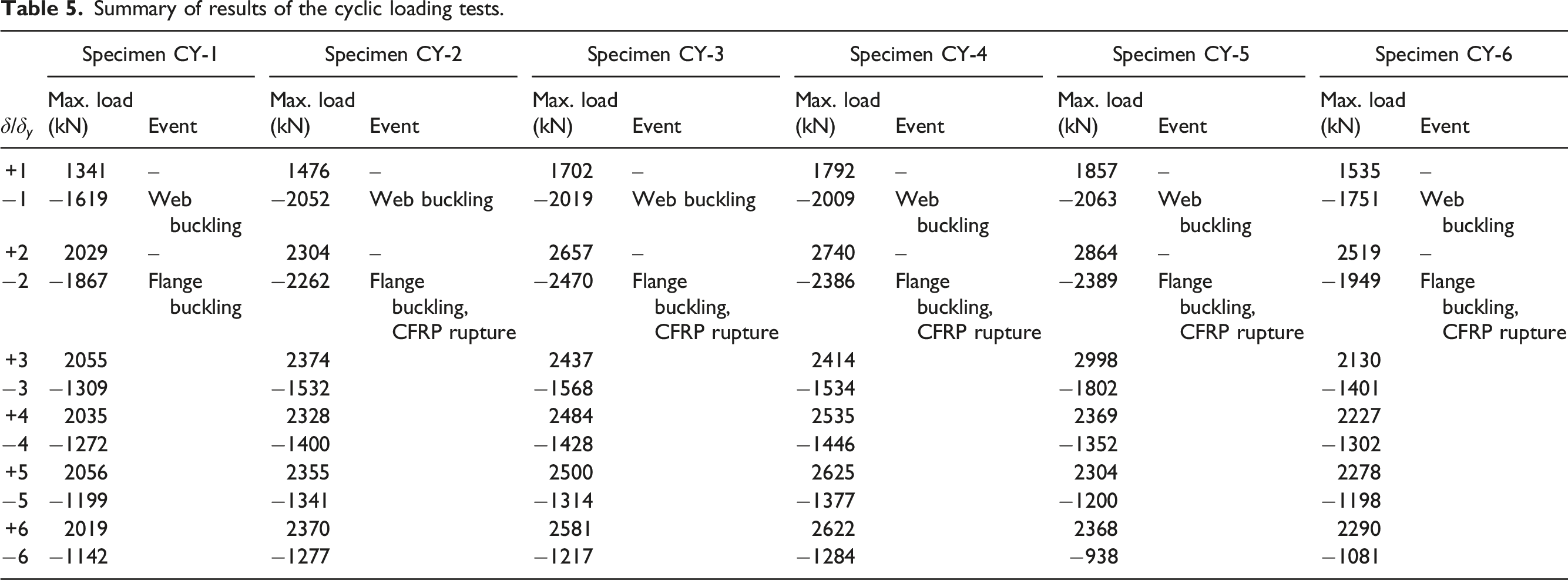
Summary of results of the cyclic loading tests.

Load–displacement hysteresis curves.

Load–displacement envelope curves.
Among these, Specimen CY-2, in which the CFRP sheets laminated only the outside of the flanges, and Specimen CY-6, in which the CFRP sheets were continuously bonded only on the inside of the flanges, had the lowest strengthening effectiveness. The reason for this low effect was that, as exhibited by Specimen CY-2, the yield strength improved by only approximately 10% when the CFRP sheets was applied with insufficient anchoring. On the other hand, for Specimen CY-6, the eccentric moment at the cross-sectional change area of the flanges increased because the CFRP sheets were bonded only on the inside of the flanges. This bonding method resulted in the load-bearing capacity of the strengthened specimen not improving in the compressive direction (Figure 13). Therefore, the load-bearing capacity of Specimen CY-6 was almost the same as that of the non-strengthened Specimen CY-1.
For Specimens CY-3, CY-4, and CY-5, the loading test results confirmed that attaching CFRP sheets to both sides of the flanges produced high strengthening effectiveness in both the tensile and compressive directions. Specifically, in the tensile direction, the improvement rates for the ultimate load-bearing capacity were 29% for Specimen CY-3, 33% for Specimen CY-4, and 46% for Specimen CY-5. In the compressive direction, the improvement rates for Specimens CY-3, CY-4, and CY-5 were 32%, 28%, and 28%, respectively (Figure 13). The ultimate load-bearing capacity of Specimen CY-5 in the tensile direction was larger than those of Specimens CY-3 and CY-4 because Specimen CY-5 had twice as many CFRP layers bonded in it. However, the improvements in the ultimate load-bearing capacity in the compressive direction were the same for these specimens. Therefore, this result confirmed that the noncontinuous CFRP sections bonded on the inner side of the diagonal member, as proposed for the methods A (CY-3) and B (CY-4), had no impact on the strengthening effectiveness against repeated forces. However, at a loading level of −2δ y , after plastic buckling occurred on the flanges, the load-bearing capacity of all the strengthened specimens rapidly decreased. This decrease was primarily due to the significant CFRP rupture caused by the large deformation of the flanges from buckling. Furthermore, in the remaining loading loops, the load-bearing capacity of the strengthened specimens in the tensile direction also decreased owing to CFRP rupture. Therefore, future research studies will examine suppressing rapid decreases in the load-bearing capacities of strengthened specimens to increase their ductility.
Failure condition
Figure 14 shows the failure modes observed in all the test specimens after completion of the cyclic loading tests, whereas Table 5 lists the order of the failure modes. According to the loading test results, the initial failure mode for all the specimens was local buckling on the web, which occurred in the first loading loop (±1δ
y
). This early web buckling is attributed to the actual initial deflection of the web, measuring an average of 2.92 mm before the loading tests were conducted, exceeding the allowable value (h/250 = 1.28 mm, h was the height of the web) required by the Japan Specification for Highway Bridges (JARA, 2012). However, the buckling of the web did not reduce the load-bearing capacity of the diagonal member specimens. Instead, plastic buckling of the flanges occurred at a loading level of −2δ
y
in all the specimens. The large deformation resulting from the buckling of the flanges was the primary factor contributing to the substantial decrease in their load-bearing capacity in the compressive direction. In addition, the large deformation of the flanges caused CFRP rupture failure. Nevertheless, because of the polyurea putty with delamination-suppressing properties inserted between the CFRP sheets and steel, delamination failure did not occur between the CFRP-sheet group and steel, except in the areas where the CFRP sheets ruptured (Figure 14). Consequently, the effectiveness of the composite cross-section between the CFRP sheets and steel was maintained even after the CFRP sheets ruptured. Because of this effectiveness, the load-bearing capacity of the strengthened specimens in both the tensile and compressive directions remained greater than that of the non-strengthened specimen after the CFRP sheets ruptured (Figure 13). In Specimen CY-5, where the CFRP sheets were continuously bonded on both sides of the flanges, the CFRP sheets ruptured simultaneously on both sides of the flanges after plastic buckling occurred. Furthermore, the extent of CFRP rupture in Specimen CY-5 after the loading test was greater than those in Specimens CY-3 and CY-4. Therefore, the load-bearing capacity of Specimen CY-5 in the final loading loop (±6δ
y
) was lower than those of Specimens CY-3 and CY-4. Failure modes in the cyclic loading tests.
Energy dissipation capacities
Figure 15 shows the energy dissipation capacities of the test specimens, calculated as the area enclosed by the hysteresis curve of the load–displacement for each loading loop. This energy represents the cumulative energy dissipated by the diagonal member specimens owing to plastic deformation under repeated forces. It is also an indicator of the seismic performance of the diagonal member specimens in response to earthquakes. Figure 15 shows that as the number of loading loops increased, the cumulative energy dissipation capacity of all the specimens increased almost linearly after the first loading loop (±1δ
y
). For Specimens CY-2 and CY-6, which had the CFRP sheets bonded on only one side of the flanges, the strengthening effectiveness was limited because of insufficient CFRP anchoring and eccentric moments at the cross-sectional change areas. As a result, their energy dissipation capacities were not significantly different from that of the non-strengthened Specimen CY-1. Specifically, in Specimen CY-2, the energy dissipation capacity was approximately 6% higher than that of CY-1, whereas that of Specimen CY-6 was almost the same as that of CY-1. However, in Specimens CY-3, CY-4, and CY-5, which had the CFRP sheets applied on both sides of the flanges, there was an increasing trend in the energy dissipation capacity in each loading loop compared to that of the non-strengthened Specimen CY-1. This increase was due to the application of the CFRP-bonding methods A, B, and C, which were proposed for these specimens. These bonding methods secured the CFRP anchoring length and improved the influence of the eccentric moment on the cross-sectional change areas. In the second loading loop (±2δ
y
), where all the specimens reached the maximum load-bearing capacity in the compressive direction, the rates of increase in the energy dissipation capacity for Specimens CY-3, CY-4, and CY-5 were approximately 12%, 13%, and 12%, respectively, in comparison to Specimen CY-1. Furthermore, in the final loading loop (±6δ
y
), the energy dissipation capacity was 40.9 kN⋅m for the non-strengthened Specimen CY-1, 45.7 kN⋅m for Specimen CY-3, and 46.8 kN⋅m for Specimen CY-4, corresponding to rates of increase of 12% and 14%, respectively. However, in Specimen CY-5, the CFRP sheets ruptured in the fifth and sixth loading loops (±5δ
y
and ±6δ
y
) on both sides of the flanges to a significant extent. Consequently, in these loading loops, its energy dissipation capacity closely resembled that of the non-strengthened Specimen CY-1. Cumulative energy dissipation.
Tensile and compressive stiffnesses
Figures 16 and 17 illustrate the tensile and compressive stiffnesses, respectively, of the test specimens within the elastic range of the steel for each loading loop. In these figures, the dashed lines represent the theoretical calculation values for the non-strengthened case, whereas the dash-dotted lines represent the theoretical calculation values for the strengthened case with sufficient CFRP anchoring. The theoretical stiffnesses in the tensile and compressive directions were assumed to be equal. Furthermore, the theoretical calculation for the strengthened case includes the coefficient c
n
(as described in equation (1)). The tensile and compressive stiffnesses in the cyclic loading tests were calculated based on the relationship between the applied load and the average relative displacement measured within the 1300 mm length range of the diagonal members using equation (2). Tensile stiffness. Compressive stiffness.


As shown in Figure 16, in the first loading loop (±1δ y ), the tensile stiffness from the cyclic loading test on non-strengthened Specimen CY-1 matched the theoretical calculation. This consistency was also observed in the strengthened Specimens CY-3, CY-4, CY-5, and CY-6. These results confirm that the tensile stiffnesses of Specimens CY-3 and CY-4, on which the proposed bonding methods A and B, respectively, were applied, reached the same level of stiffness as those of Specimens CY-5 and CY-6, with sufficient CFRP anchoring. This trend was the same as that of the initial tensile stiffness of the specimens obtained from the monotonic tensile loading tests. Additionally, in the first loading loop (±1δ y ), the tensile stiffness of Specimens CY-3 and CY-4 was larger than that of the non-strengthened Specimen CY-1 by approximately 28%.
Figure 16 also shows that Specimen CY-2, with insufficient CFRP anchoring, exhibited a significantly lower tensile stiffness than those of Specimens CY-3 and CY-4. Further, in the first loading loop (±1δ y ), Specimen CY-5 had slightly higher tensile stiffness than the theoretically calculated value because of the use of twice as many CFRP sheets. After the first loading loop, the tensile stiffness of all test specimens was reduced in the subsequent loading loops owing to the large residual deformations of the web and flanges caused by buckling and the influence of CFRP rupture. Furthermore, there were no significant differences in the tensile stiffness between the strengthened Specimens CY-2 and CY-6 compared to that of the non-strengthened Specimen CY-1. However, in Specimens CY-3, CY-4, and CY-5, although the tensile stiffness decreased in each loading loop, the tensile stiffness remained approximately 35% higher than that of the non-strengthened Specimen CY-1. Moreover, the tensile stiffness behaviours of Specimens CY-3 and CY-4 in all loading loops were identical to that of Specimen CY-5, even though the CFRP sheets in these specimens were not continuously bonded to the inner side of the diagonal member.
Similar to the tensile stiffnesses, the compressive stiffnesses, shown in Figure 17, of all the test specimens decreased in each loading loop due to flange and web buckling, along with CFRP rupture. Moreover, Specimen CY-6 exhibited a compressive stiffness identical to that of the non-strengthened Specimen CY-1, owing to the influence of the eccentric moment at the cross-sectional change areas. However, the compressive stiffness of Specimen CY-2 improved slightly by approximately 16% compared with that of Specimen CY-1 in each loading loop. In particular, for Specimens CY-3, CY-4, and CY-5, the compressive stiffnesses obtained were at the same level across all loading loops and were higher than that of the non-strengthened Specimen CY-1 by 31%. Therefore, this result confirmed that the noncontinuous CFRP sections bonded on the inner side of the diagonal member, as proposed for the methods A (CY-3) and B (CY-4), had no impact on the effectiveness at enhancing the stiffness under repeated forces.
Conclusions
The study conducted monotonic tensile and cyclic loading tests on 11 diagonal tension member specimens to evaluate the effectiveness of the proposed CFRP-bonding methods in enhancing load-bearing capacity and seismic behaviour. The main findings of this study are outlined below: (1) The monotonic tensile loading tests showed that all the strengthened specimens exhibited higher initial tensile stiffness than the non-strengthened specimen, especially with the CFRP sheets bonded on both sides of the flanges in strengthening methods A and B. (2) Methods A and B significantly improved the yield strength and ultimate load-bearing capacity of the specimens by approximately 27% and 51%, respectively, achieving the same strengthening level as the specimen with sufficient CFRP anchoring. (3) Under the monotonic tensile loading tests, the delamination of the CFRP sheets occurred only after steel yield failure in all the strengthened specimens owing to the application of polyurea putty with high elongation and a low elastic modulus. (4) The cyclic loading tests confirmed that strengthening methods A and B exhibited high strengthening effects, with an increase in the ultimate load-bearing capacity by approximately 33% and 32% under tension and compression, respectively. Moreover, the noncontinuous CFRP sections bonded on the inner side of the diagonal tension member in Methods A and B had no impact on the strengthening effectiveness under repeated forces. (5) As the number of loading loops increased, the energy dissipation capacities of all the specimens showed a linear increase after the first loading loop (±1δ
y
). In the final loading loop (±6δ
y
), the energy dissipation capacity increased by 12% and 14% in the specimens strengthened by Methods A and B, respectively, compared to the non-strengthened specimen. (6) The cyclic loading tests showed a decrease in tensile and compressive stiffness of all the specimens at each loading loop due to flange and web buckling and CFRP rupture. However, strengthening with Methods A and B maintained approximately 35% higher stiffnesses than the non-strengthened specimen. Furthermore, the stiffness behaviours of the specimens strengthened using Methods A and B were the same across all the loading loops.
Suppressing rapid decreases in the load-bearing capacities of strengthened diagonal tension members due to CFRP rupture under repeated forces to increase their ductility will be investigated in future studies. Additionally, there is a need to construct a nonlinear finite element model to predict the relationship between the number of bonded CFRP sheets and the ultimate load-bearing capacity of strengthened diagonal members to establish appropriate methods for enhancing strength.
Footnotes
Acknowledgements
The authors are grateful to Dr. Masafumi HATTORI of Nippon Expressway Research Institute Co. and Dr. Yuya HIDEKUMA of Nippon Steel Chemical & Material Co. for their assistance during the loading tests.
Author contributions
Declaration of conflicting interests
The author(s) declared no potential conflicts of interest with respect to the research, authorship, and/or publication of this article.
Funding
The author(s) disclosed receipt of the following financial support for the research, authorship, and/or publication of this article. This work was supported by the University of Danang, University of Science and Technology, code number of Project: T2023-02-45.

Data availability statement
All data, models, and codes generated or used during the study appear in the submitted article.