
Abstract
Given the rapid expansion of the wind energy sector, many wind farms are being constructed in regions susceptible to earthquakes, making it crucial to assess the seismic fragility of wind turbines. However, limited research efforts have been devoted to investigating the influence of earthquake ground motion types on the responses of wind turbines. In the present study, an elaborate three-dimensional finite element model of an example wind turbine is developed using ABAQUS, and the dynamic responses of the wind turbine under four types of ground motion are recorded in the same earthquake, namely a near-field pulse-like record with the forward-directivity effect ground motion, a near-field pulse-like record with the fling-step effect ground motion, a near-field non-pulse ground motion, and a far-field ground motion, are analysed and compared. In addition, an investigation is carried out into the influence of permanent ground displacement on the seismic responses of the wind turbine. Following that, the fragility curves for the specified damage states of the wind turbine tower are constructed, considering different ground motion types and pulse periods. The results show that the seismic responses of wind turbines are significantly influenced by the ground motion type and pulse period, while the permanent ground displacement has a marginal effect.
Keywords
Introduction
As environmental issues become more prominent and traditional energy sources continue to deplete, the development and utilization of wind energy, one of the most potential renewable energy sources, has gained increasing attention (Li et al., 2015). The Global Wind Energy Council (2023) reported that the annual onshore wind power installations are expected to exceed 100 GW for the first time by 2024, and the cumulative installed capacity is projected to reach 680 GW over the next 5 years. As the output power of wind turbines is proportional to the rotor area, current wind turbines tend to be built with huge rotors and slender towers to extract more wind resources, making them vulnerable to external dynamic excitations. In addition, many wind farms are developed in seismically-prone regions, such as the west coast of the US and the east coast of Asia (Prowell and Veers, 2009a). It is crucial to estimate the safety and reliability of wind turbines when subject to earthquakes.
Over the last few decades, extensive experimental research and numerical studies have been carried out to investigate the seismic behaviour of wind turbines. For example, Prowell et al. (2009b) performed full-scale shaking table tests of a 65 kW wind turbine and developed a beam-column finite element (FE) model to simulate the tower responses under seismic loads. Their results showed that the tower response was governed by the first vibration mode. However, for taller wind turbines, the tower response is also affected by higher vibration modes. Patil et al. (2016) concluded that the wind turbine tower was most susceptible to overturning during an earthquake event, followed by yielding, permanent deformation and overall buckling. Li et al. (2019) investigated the seismic responses of wind turbines during long-period ground motions. Sadowski et al. (2017) considered initial welding imperfection to investigate the ground motion intensity at which damage initiates and the failure location of a 1.5 MW wind turbine. In addition to horizontal seismic motion, as a high-rise structure, vertical seismic motion has attracted particular attention in wind turbine analyses. The results in previous studies indicated that the vertical ground motion not only transferred plastic hinges to more slender (weaker) parts of the tower (Sadowski et al., 2017) but also increased the acceleration responses of wind turbines in the vertical direction, potentially leading to the nacelle’s acceleration-sensitive electronic products to fail (KjφRlaug and Kaynia, 2015), as well as affecting the buckling stress of the tower (James and Haldar, 2022). Therefore, vertical seismic motion is also deemed a critical load in the wind turbine design.
It should be noted that the above-mentioned studies did not consider the influence of different ground motion types. Earthquake ground motion is impacted by various factors, including site conditions, fault distance, and source mechanism, which possess inherent randomness and discreteness. The specific characteristics of ground motion play a critical role in determining the structural seismic responses. As a result, many researchers opt to utilize the earthquake ground motion as prescribed in Ref. (ATC, 2009) for structural fragility analyses. It is important to note, however, that the recommended ground motions in Ref. (ATC, 2009) encompass three types: far-field (F-F) earthquake ground motion, near-field non-pulse (N-F-N-P) earthquake ground motion, and near-field pulse-like (N-F-P) earthquake ground motion. The report does not distinguish the two forms of N-F-P ground motion. In fact, for N-F-P earthquake ground motion, there are two primary forms of velocity pulse effects. The first is the directional velocity pulse resulting from fault rupture propagation. This pulse is caused by the movement of the fault during an earthquake and can have a significant influence on the ground motion characteristics. The second form is the velocity pulse accompanied by the fling-step effect, which is generated by the permanent ground displacement. Both velocity pulse effects contribute to the unique characteristics of N-F-P earthquake ground motion and should be taken into consideration when analyzing the structural seismic responses. Some research works have been carried out in this area, and they are summarized below.
Sadowski et al. (2017) found that N-F-P ground motions with high vertical accelerations caused larger tower responses. Comparing the N-F-P earthquake ground motion with the F-F earthquake ground motion, Fan et al. (2019) observed that the mean displacement at the tower top when subjected to the N-F-P ground motion was larger than that under the F-F ground motion due to the sudden release of energy in the pulse-like ground motion. Zheng et al. (2022) reported that N-F-P ground motions not only amplified the fore-aft and side-to-side displacements at the top of the tower but also led to higher failure locations than F-F ground motions. Sahraeian et al. (2023) compared the seismic responses of wind turbines under N-F-P and F-F ground motions. The results showed that despite the shorter duration and lower intensity, the responses under N-F-P ground motions were larger. Eslami and Ghorbani (2023) concluded that offshore wind turbines exhibited similar ranges of acceleration response for both N-F-P and F-F ground motions, but other response parameters (e.g., lateral displacement, rotation, and settlement) under N-F-P ground motions were more significant. Stamatopoulos (2013) investigated the effect of N-F-P ground motions on the seismic responses of wind turbines. The results indicated that the elastic response spectrum provided by the Greek National Aseismic Code was inaccurate in addressing the unique response characteristics of wind turbines under N-F-P ground motions. Xu et al. (2021) and Ali et al. (2020) studied the effect of near-field (N-F) seismic records with and without pulses on the failure mode of wind turbines, and the results showed that the seismic response of the wind turbine under N-F ground motions with pulses was significantly larger than that under N-F ground motions without pulses. Ren et al. (2021) performed shaking table tests of a 1/20 scale 2 MW wind turbine under N-F-P ground motions, and the test results confirmed that pulse-like records could considerably increase the strain, shear forces, and accelerations of the tower. This observation highlights the significance of considering N-F-P effects when conducting seismic analysis for wind turbines again.
Furthermore, as evidenced by the strong ground motions recorded during previous severe earthquake events, some N-F ground motions contain significant permanent displacements, and this special characteristic is mainly induced by the fling-step effect. Chaudhari and Somala (2021, 2022) compared the behaviour of offshore wind turbines between near-field pulse-like records with the forward-directivity effect (N-F-F-D)earthquake ground motion and near-field pulse-like record with the fling-step effect (N-F-F-S) earthquake ground motions. The results indicated that the wind turbine responses were significantly influenced by the number of pulses and the pulse period, and with the increased pulse period, the wind turbine exhibited greater sensitivity to the velocity pulse with the forward-directivity effect than that with the fling-step effect. Moreover, Sigurðsson et al. (2020) investigated the wind turbine responses under a total of 69 N-F-F-D earthquake ground motions. The results demonstrated that peak ground velocity and main pulse period were two key parameters that influence the structural responses, especially when the pulse period was nearly similar to the fundamental period of the wind turbine, larger responses were obtained. This indicates that, in addition to the type of seismic motion, the period of N-F-P ground motions is another parameter that should be considered in the dynamic analysis of wind turbines.
The above critical literature review reveals that although some research has been conducted to examine how ground motion impulse affects the seismic responses of wind turbines, limited research efforts are devoted to the influences of ground motion type, permanent ground displacement, and pulse period.
To this end, the seismic behaviours of a 5 MW wind turbine subjected to different ground motion types, permanent ground displacements, and pulse periods are systematically investigated in this paper. Firstly, a three-dimensional (3D) FE model of the wind turbine is established in ABAQUS and validated against the previous study. Subsequently, the seismic responses of the wind turbine are investigated and compared under different ground motion types and permanent ground displacements in one historic earthquake record. Fragility curves are developed for different ground motion types and pulse periods.
Numerical model
Properties of the 5 MW wind turbine.

FE model
The NREL 5 MW wind turbine is developed in ABAQUS. It should be noted that only the masses of the nacelle, hub, and blades were considered and modelled by a concentrated mass element at the top of the tower in the previous studies (Fan et al., 2019; Patil et al., 2016; Zuo et al., 2018). However, the dynamic responses of wind turbine structures are influenced by the coupling effect within these structural components (i.e., the tower, nacelle, hub, and blades) (Ke et al., 2015). Therefore, the nacelle, hub, blades, and tower are modelled explicitly in the present study. The detailed modelling techniques are introduced as follows.
The nacelle and hub are modelled by solid elements (C3D8R element type) and the tower and three blades are developed by shell elements (S4R element type). The nacelle and hub are connected by using a tie connection in ABAQUS and they are also tied to the top of the tower and the root of the blades. Compared to the nacelle, hub, and tower, the modelling of the blades is more complicated due to the irregular cross-sections of the blades. Eight distinct airfoil sections are first created in Solidworks and the geometrical model of the blade is developed by lofting these airfoil sections then it is imported into ABAQUS and assembled with the nacelle, hub, and tower. Moreover, the element size for the nacelle, hub, and tower is set to 1 m, and the element size for each blade is set to 0.5 m in the developed model to balance the computational accuracy and efficiency. Notably, the blade’s mesh undergoes uniform refinement via local partitioning to avoid convergence problems in subsequent dynamic analysis. Figure 1 shows the FE model of the NREL 5 MW wind turbine. The modelling method adopted in this study can be extended to other wind turbines with various sizes and power capacities. However, it should be noted that the rotation of the rotor is not considered in this study, because the seismic responses of wind turbines are of interest. During an earthquake, wind turbines are in an emergency shutdown state, causing the blades to remain stationary. When considering the rotation of the blades, a hinge connection between the tower and the blades should be defined, and thus the rotational degree of freedom along the outer plane of the rotor is released. FE model of the wind turbine.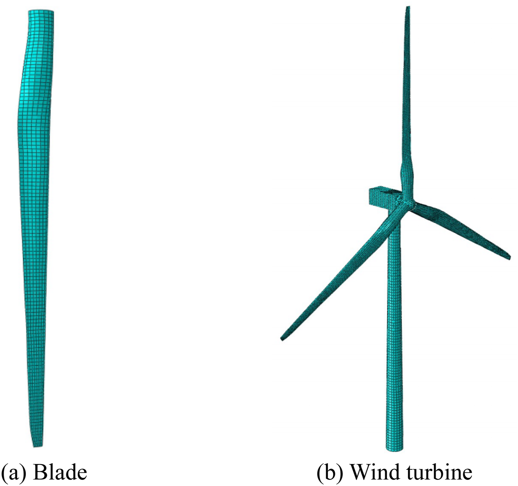
Material properties of the 5 MW wind turbine.

The damping of an onshore wind turbine is comprised of two components: aerodynamic damping and structural damping. The aerodynamic damping is generated by the relative velocity between the inflow wind and the rotating blades and it is dependent on the wind speed and the rotational speed and difficult to be accurately predicted. However, wind turbines normally stop rotating when they are subjected to earthquakes. Therefore, the aerodynamic damping is ignored and only the structural damping is considered by using Rayleigh damping in this study. The structural damping ratios of the blades and tower are 0.5% and 1%, respectively, as given in Table 1.
Model validation
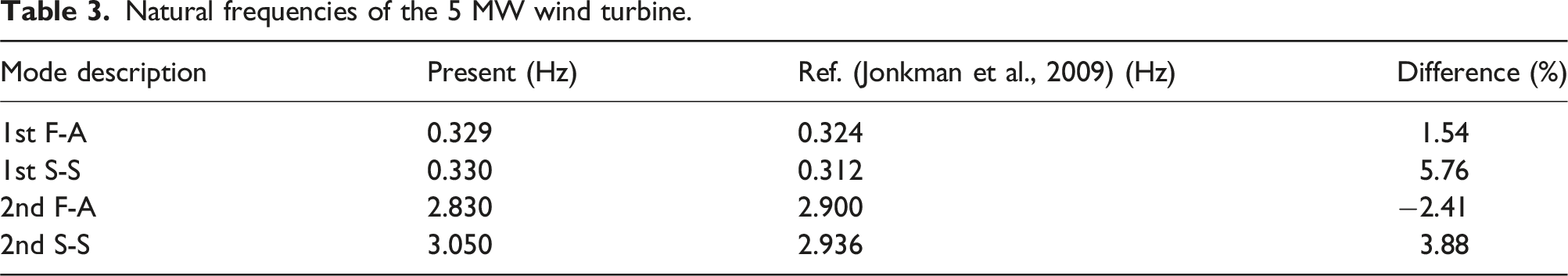
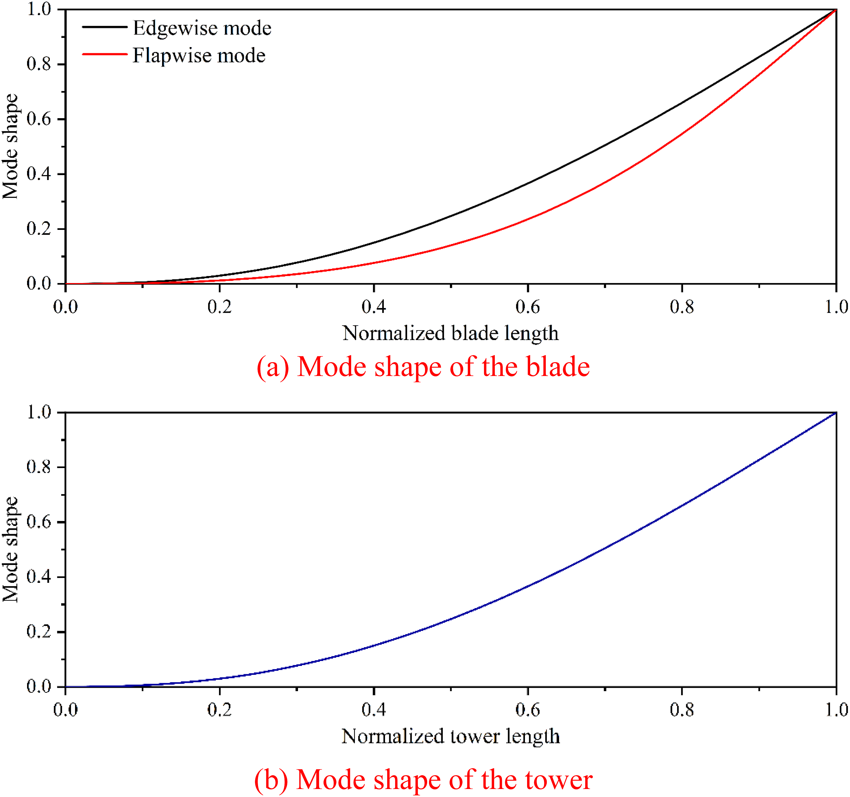
To verify the accuracy of the developed FE model, an eigenvalue analysis is conducted to determine the natural frequencies and mode shapes. Figure 2 shows the first two vibration modes of the tower in the fore-aft (F-A) and side-to-side (S-S) directions, and their corresponding frequencies are then compared with study Ref. (Jonkman et al., 2009) in Table 3. As the tower is almost symmetrical, the first two vibration modes in the F-A and S-S directions are thus almost the same. For each blade, the flapwise and edgewise stiffnesses are different, and higher vibration modes occur in Figure 2. The natural frequencies agree well with those reported in Ref. (Jonkman et al., 2009), and the largest difference is 5.76%. To validate the developed model further, the first mode shapes of the blade and tower are shown in Figure 3. The mode shapes are consistent with those reported in Ref. (Sun and Jahangiri, 2018). Mode shapes of the tower in ABAQUS. Natural frequencies of the 5 MW wind turbine. Mode shapes of the blade and tower.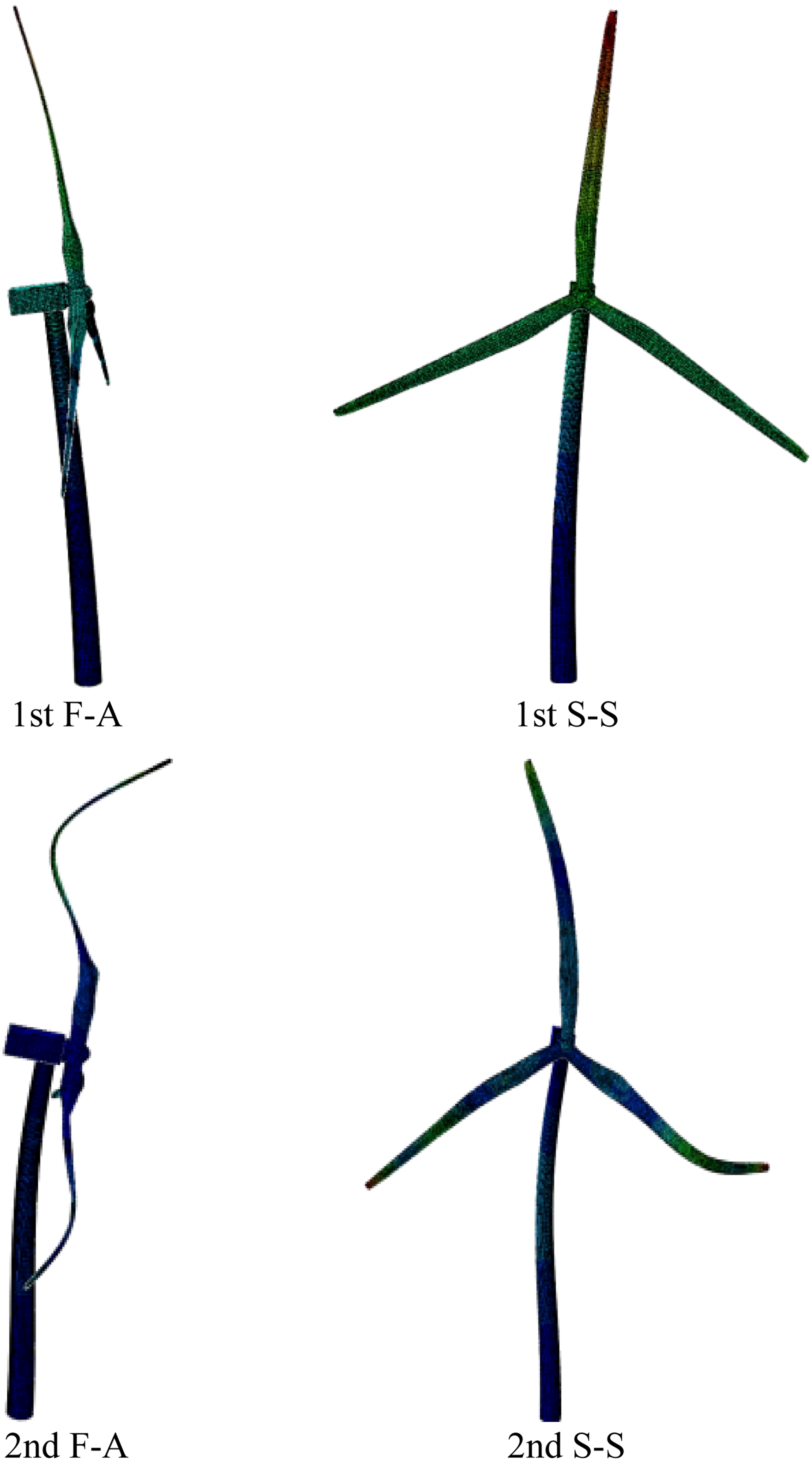
Seismic fragility method and damage state definition
Seismic fragility method
Structural fragility is referred to as the proportional likelihood of a prescribed structural demand reaching or exceeding the structural capacity at a specific stimulation intensity. As mentioned above, the seismic damage to the tower is of interest in the present study, therefore, only the fragility curves of the tower are constructed by using the rotational and displacement responses obtained from numerical simulations. In seismic response analysis, fragility curves can be generated by using various methods, including incremental dynamic analysis (IDA) (Chaudhari and Somala, 2021), cloud analysis (Ali et al., 2020), and multiple stripe analysis (Yuan et al., 2017), etc. In the IDA method, all considered seismic motions are scaled to the selected seismic intensity levels and nonlinear time history analyses are conducted to assess the structural responses under each seismic motion. Although a large number of numerical simulations are required by using the IDA method, this method is very straightforward and adopted in the present study to generate the fragility curves of the wind turbine tower. The conditional probability of exceeding a predefined threshold (i.e., the fragility function) is defined as
The structural demand of the wind turbine tower under seismic loads is estimated by a power law function as (Cornell et al., 2002)
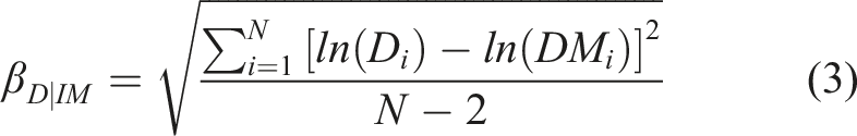
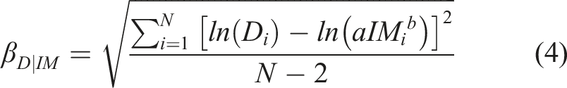
By substituting equations (2) and (3) into equation (1), the final probabilistic demand model can be expressed as equation (5).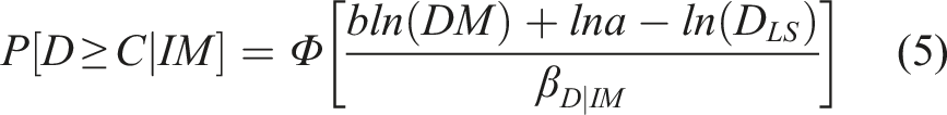
Damage state definition
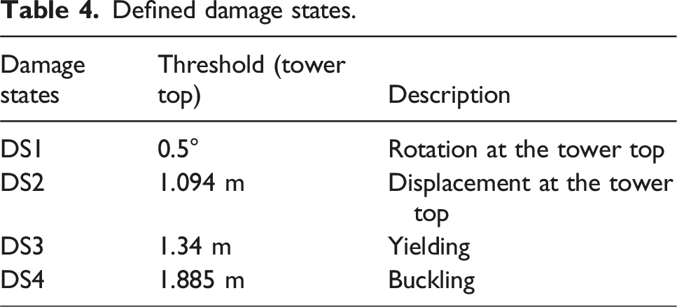
The structural damage state serves as a parameter for evaluating the extent of damage incurred by a structure during ground motions. The selection of damage states depends on the specific characteristics of the structure. Referring to Ref. (Nejad et al., 2019), the evaluation of wind turbine damage levels takes into account both the serviceability limit state (SLS) and the ultimate limit state (ULS). Considering the distinct requirements of wind turbines, four damage states are defined in the present study and summarized as follows:
Wind turbine towers are equipped with long cantilevered blades at their tops. Excessive rotation and displacement at the top of the tower can reduce power efficiency and potentially lead to collisions between the blades and the tower (Mo et al., 2017). According to Det Norske Veritas (2014), the allowable rotation threshold for the monopile at the mudline is ±0.5°. However, this standard does not address the rotation at the tower top, and the criterion for the monopile rotation is out of the scope of this study. For simplicity, some researchers (e.g., Ali et al., 2020; Bisoi and Haldar, 2014; Risi et al., 2018) used ±0.5° of the rotation at the tower top as the damage threshold. Therefore, in this study, Damage State 1 (DS1) is defined as a maximum tower top rotation of 0.5°, aligning with the serviceability limit state. In addition, Asareh et al. (2016) proposed a threshold displacement ratio of 1.25% of the tower height to ensure safe wind turbine operation, which is defined as Damage State 2 (DS2). For a tower height of 87.6 m, as listed in Table 1, this 1.25% displacement ratio corresponds to a displacement of 1.094 m at the tower top. While these two damage states (i.e., DS1 and DS2) do not necessarily indicate tower failure, they are crucial safety measures during seismic events.
Moreover, the tower is susceptible to yielding or buckling during earthquake events, which can ultimately result in collapse. Kim et al. (2014) found that pushover analysis, although static, provided results that were consistent with dynamic analysis. This is because wind turbines, as an inverted cantilever structure, exhibit a one-to-one relationship between maximum displacement and maximum stress under simple loading conditions. For this reason, a pushover analysis is conducted on the tower to examine its nonlinear behaviour characteristics and establish appropriate thresholds for different ULSs. This analysis allows for a comprehensive understanding of the tower’s response under seismic conditions and aids in setting criteria for assessing its structural integrity. The pushover analysis is conducted by incrementally applying displacement at the top of the tower in the F-A direction and an initial imperfection of 1/1000 of the first buckling mode is considered (Dimopoulos and Gantes, 2012). The maximum bending moment and shear force are observed at the bottom of the tower, and the pushover analysis results can illustrate the correlation between the bending moment and shear force at the tower bottom and the displacement at the tower top. The present study adopts the normal stress as the yield criterion for the wind turbine tower (Zuo et al., 2020), which is calculated by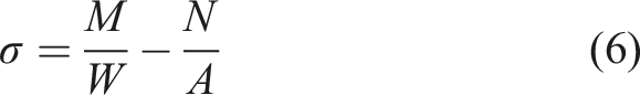
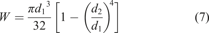
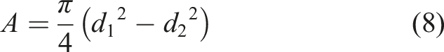
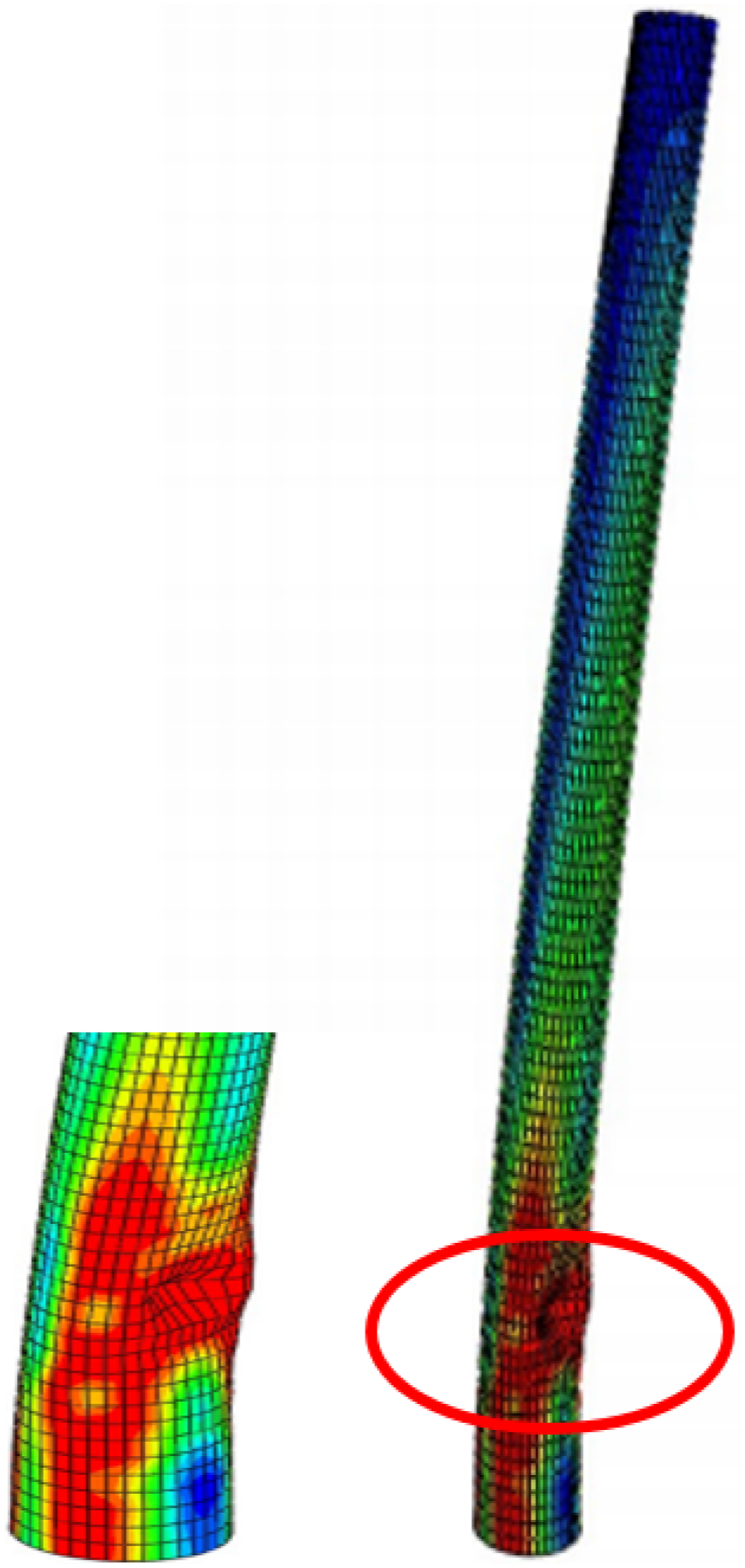
Figure 4(a) shows the relationships between the bending moment and shear force at the bottom of the tower and the displacement applied at the top of the tower, and Figure 4(b) shows the normal stress at the tower base by substituting the bending moment and shear force into equations (6)–(8). It is clear that the internal forces (bending moment and shear force) and normal stress linearly develop with increasing the displacement imposed at the tower top before the yielding. The nonlinear behaviour of the tower initiates at a displacement of 1.34 m, signifying the onset of yielding in the structure. In addition, when the displacement at the top of the tower is 1.885 m, the internal force/normal stress-displacement relationships show a snap-back behaviour because of the local buckling of the tower. After that, the internal forces and normal stress decrease with the increment of the displacement. Figure 5 shows the local buckling phenomenon observed in the tower from the pushover analysis. In order to enhance the clarity of the results, the blades are not included in the figure. As indicated, the buckling of the tower appears at a location of approximately 15 m above the tower base. Asareh et al. (2016) observed that buckling damage occurs approximately 20 m above the tower base when the tower top displacement reaches 2.2 m. The discrepancy between these results is mainly due to the different steel material properties used for the tower, leading to slightly different buckling locations and tower top displacements. Therefore, DS3 and DS4 are defined as displacements of 1.34 m and 1.885 m at the tower top, respectively, and the four damage states defined are shown in Table 4. Relationships between bending moment, shear force, normal stress and displacement. Tower buckling. Defined damage states.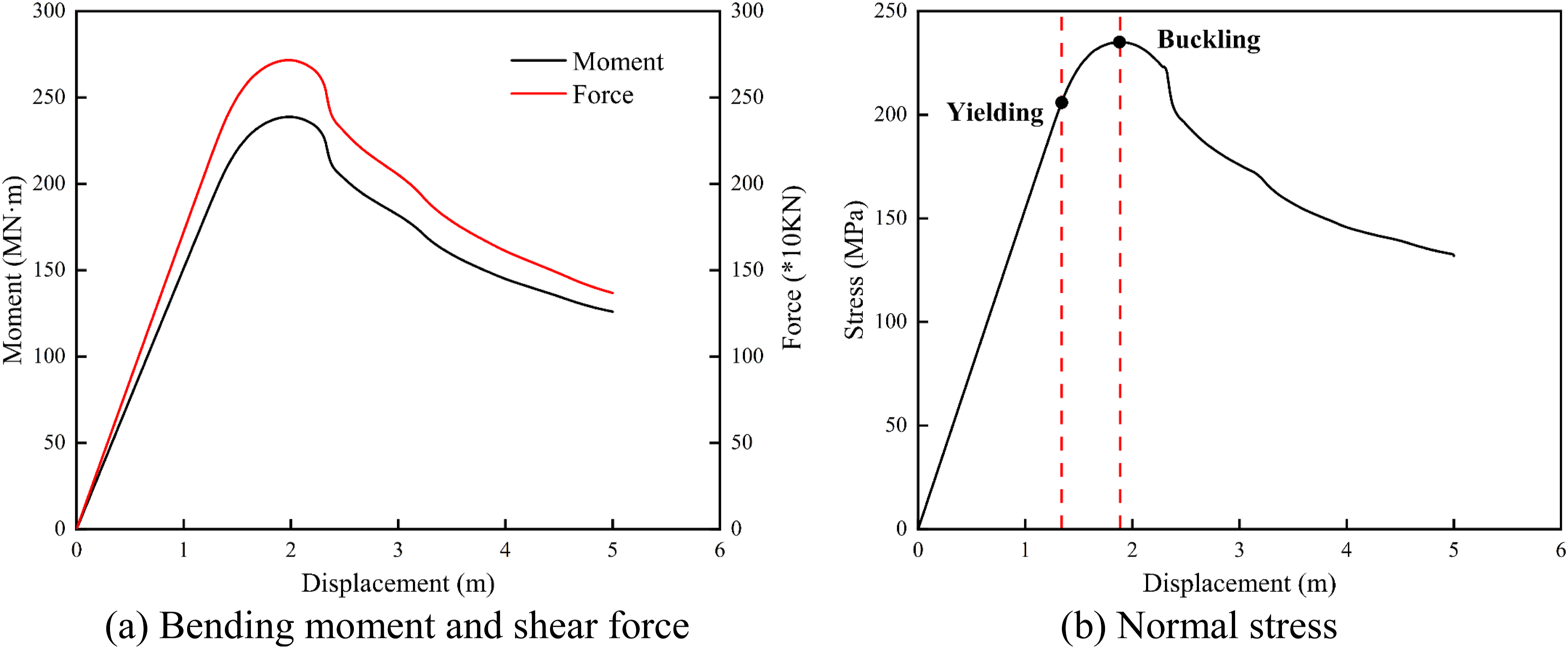
In summary, the steps for constructing the fragility curves of the wind turbine tower under earthquake ground motions are as follows: (1) Develop and validate the FE model; (2) Define the damage states; (3) Select appropriate earthquake ground motions, which will be introduced in the following section; (4) Perform IDA to obtain the structural demand; (5) Develop the fragility curves by using equation (1).
Considered earthquake ground motions
To systematically investigate the seismic performances of wind turbine structures under different ground motion excitations, four cases are considered. In the first case, four earthquake ground motion types recorded at different locations in the same earthquake are used as inputs to enquire about the influence of different ground motion types. In the second case, earthquake ground motions with different permanent ground displacements are investigated. In the third and fourth cases, more sets of ground motions with different ground motion types and pulse periods are selected to further investigate their influences on the seismic fragility of the wind turbine.
Different types of ground motions in one earthquake
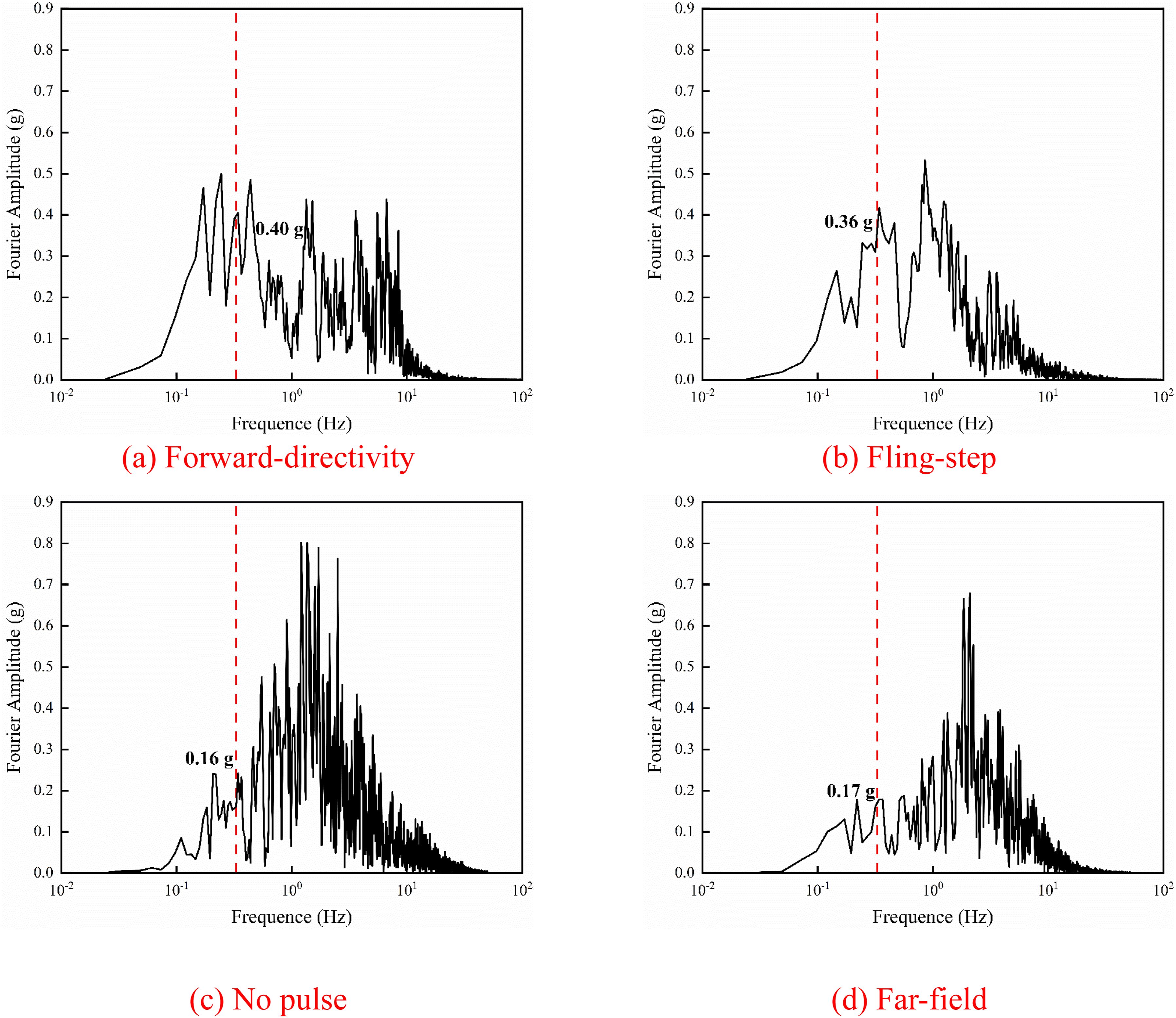
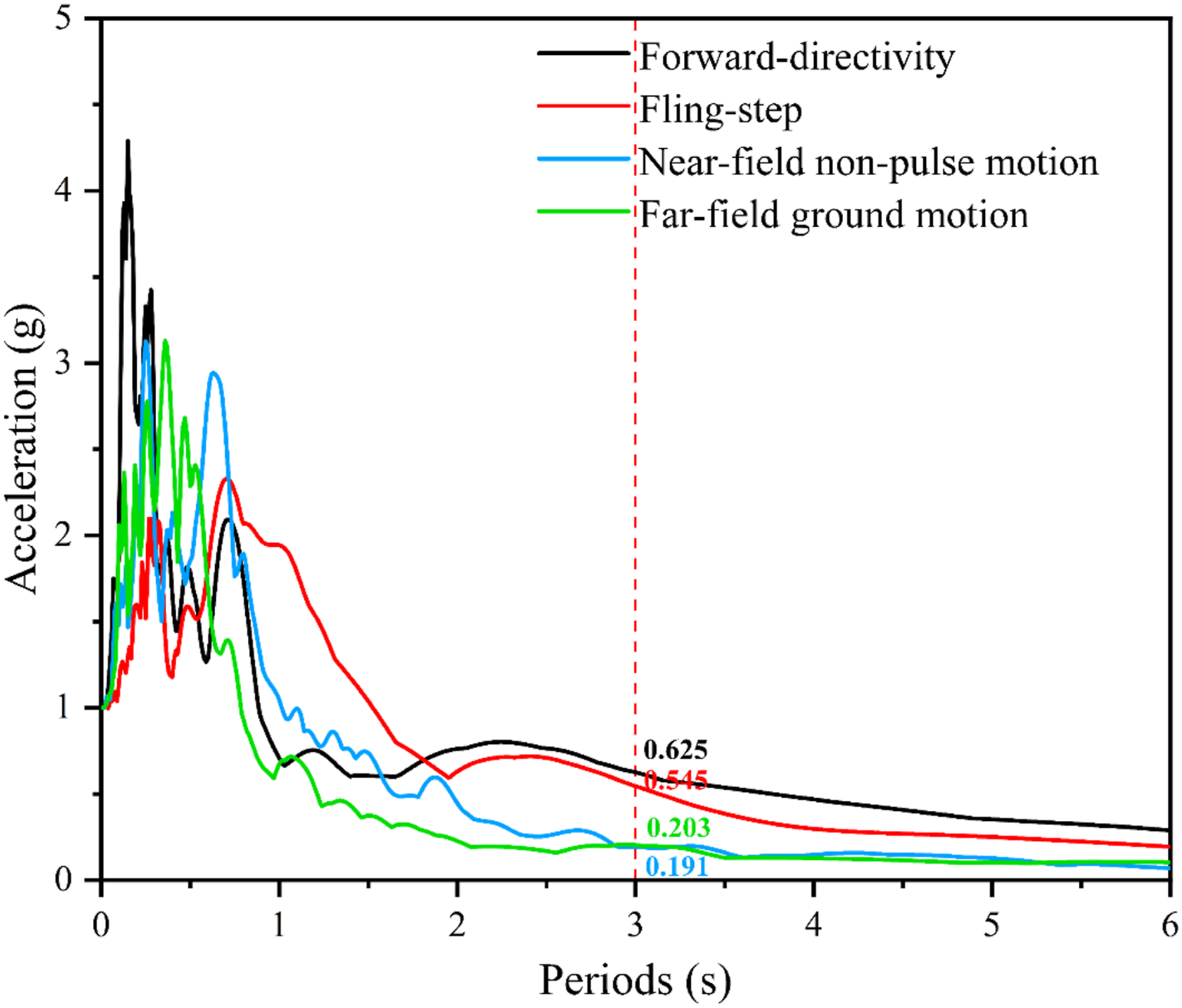
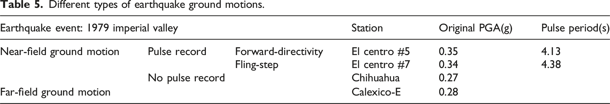
As discussed in the introduction, the earthquake forward-directivity effect could lead to the obvious velocity pulse in the ground motion, and the fling-step effect may result in permanent ground displacement. Due to the significant differences in structural dynamic response caused by N-F and F-F ground motions, it largely depends on the influence of fault rupture mechanisms. Therefore, to investigate the influence of ground motion types on the responses of wind turbines, this study selects four earthquake ground motions recorded from the same event 1979 Imperial Valley earthquake. These include the N-F ground motions with and without pulses, as well as the F-F ground motion. It is important to note that various earthquake events can exhibit these ground motion types, and the event chosen for this study is selected at random for investigation. Figure 6 shows the acceleration, velocity, and displacement time histories, in which all the PGAs are scaled to 1 g to remove the influence of ground motion amplitudes. The typical analytical pulse curves are also shown in Figure 6 to more clearly show the pulses (the red and green curves). It can be seen that antisymmetric and symmetrical velocity pulses exist in Figure 6(a) and (b), which are typical characteristics of N-F-F-D and N-F-F-S ground motions, respectively. Figure 7 shows the Fourier spectra of the ground motions recorded during the 1979 Imperial Valley earthquake. The frequency content differs among the four types of ground motions. Particularly, the N-F-F-D ground motion contains a higher proportion of high-frequency components. Figure 8 shows the normalized response spectra. Acceleration, velocity, and displacement time histories of different earthquake ground motion types. Fourier spectra of different earthquake ground motions. Acceleration response spectra of different earthquake ground motions.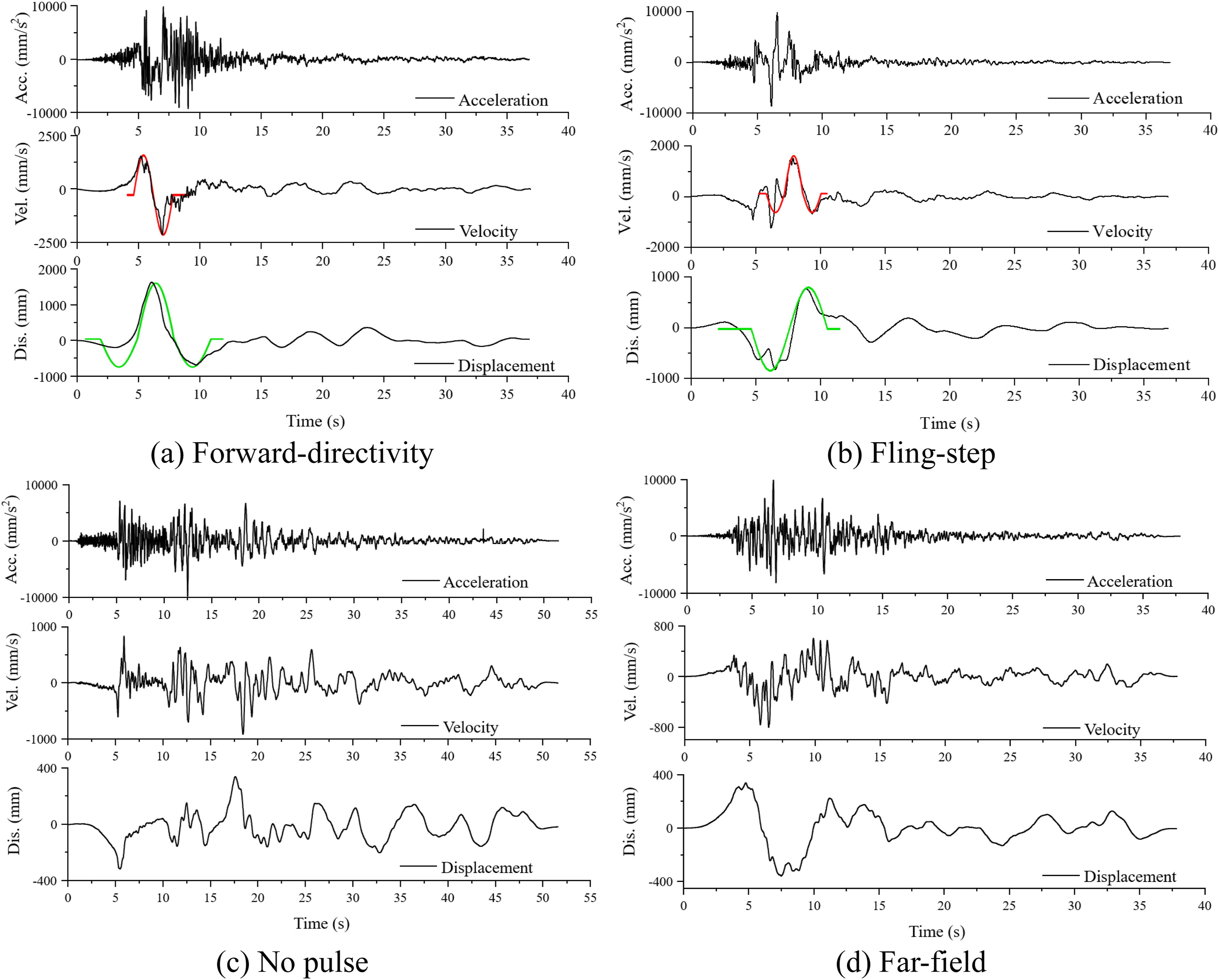
Ground motions with different permanent ground displacements
The fling-step effect is caused by permanent static displacements in the sliding direction of the ground, which is manifested as a “step-like” function in the displacement time history of earthquake ground motions. However, it should be noted that there is no permanent displacement in the earthquake records downloaded from the Pacific Earthquake Engineering Research Centre (PEER, 2011). This is because the permanent ground displacements are filtered out to avoid the baseline errors in the acceleration time history of seismic motions (Burks and Baker, 2014). To investigate the influence of permanent ground displacements caused by the fling-step effect on wind turbines, the baseline correction method proposed by Lin et al. (2018) is adopted in the present study, and three different permanent ground displacements of 400 mm, 800 mm, and 1200 mm are added to the ground motions shown in Figure 6(b). Figure 9 shows the time histories of acceleration, velocity, and displacement for N-F earthquakes featuring varying permanent ground displacements. Similar to the different ground motion types discussed in Figure 6, the PGAs of the ground motions with different permanent ground displacements are scaled to 1 g. As depicted in Figure 9, although the permanent ground displacements are different, the acceleration and velocity time histories of the four seismic motions are almost the same because the baseline correction method only corrects the quasi-static component of the ground motion without altering its dynamic component. N-F-F-S ground motions with different permanent ground displacements.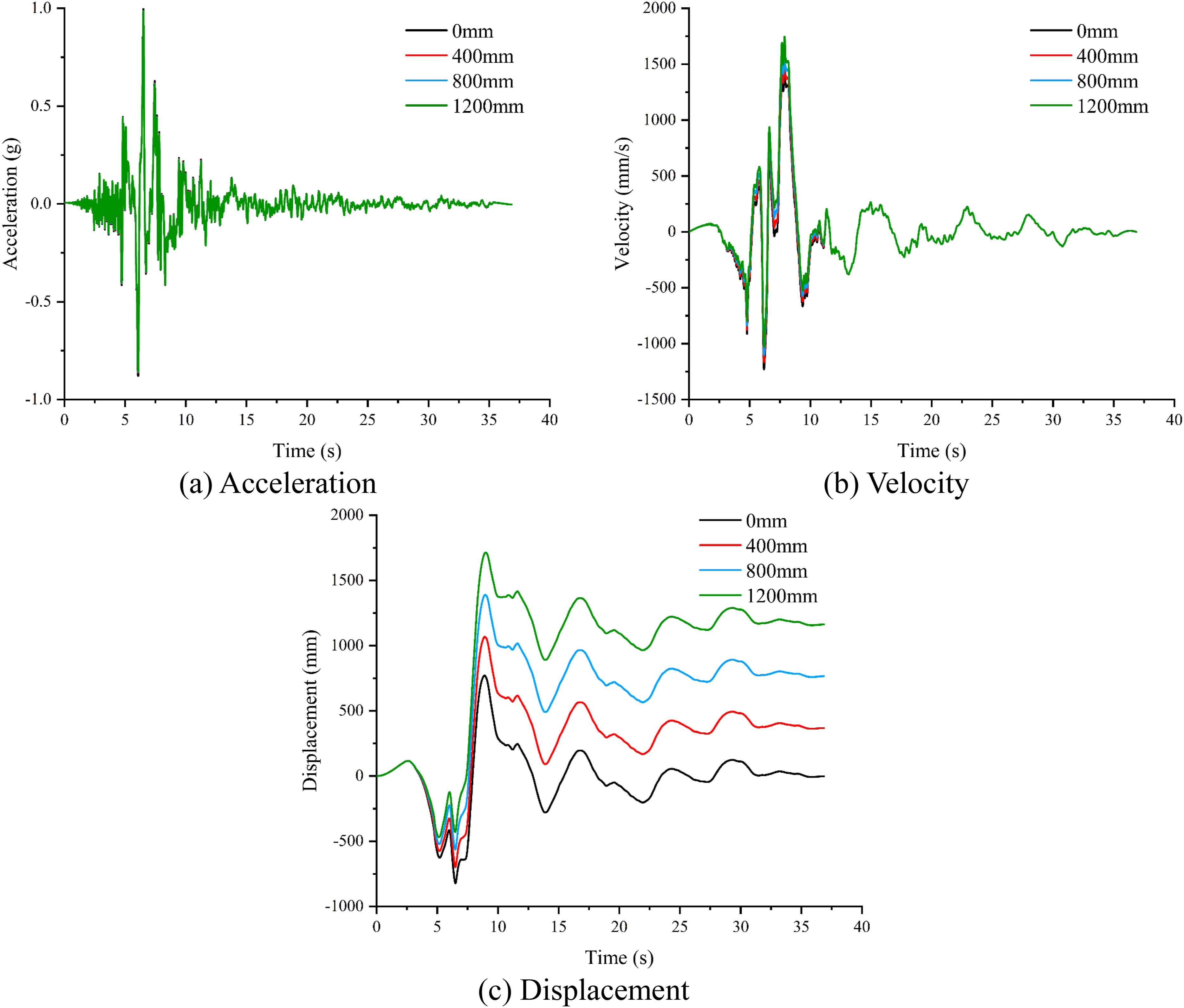
Ground motions with different types and pulse periods
To comprehensively explore the influences of ground motion type and pulse period on the seismic responses of the wind turbine, five different earthquake ground motion types in different earthquake events are also considered, namely A, B, C, D, and E sets. Specifically, set A consists of 20 F-F earthquake ground motions, and set B has 20 N-F-N-P earthquake ground motions. Moreover, PGV/PGA is normally used to estimate the forward-directivity effect of an earthquake ground motion’s velocity pulse patterns (Liao et al., 2001), and the larger the value, the more obvious the pulse characteristics. Therefore, the N-F-F-D earthquake ground motions are further divided into two sets, which are PGV/PGA <0.15 (N-F-F-D(PGV/PGA <0.15), set C) and PGV/PGA >0.15 (N-F-F-D(PGV/PGA >0.15), set D), respectively. In addition, there are 10 N-F-F-S earthquake ground motions in set E. All the earthquake ground motions in the five sets are downloaded from the PEER (2011), and their detailed information is shown in Table A1 in the appendix. Figure 10 shows the acceleration response spectra of the ground motions and the mean spectra in each ground motion type are compared in Figure 10(f). Acceleration response spectra of different ground motion types.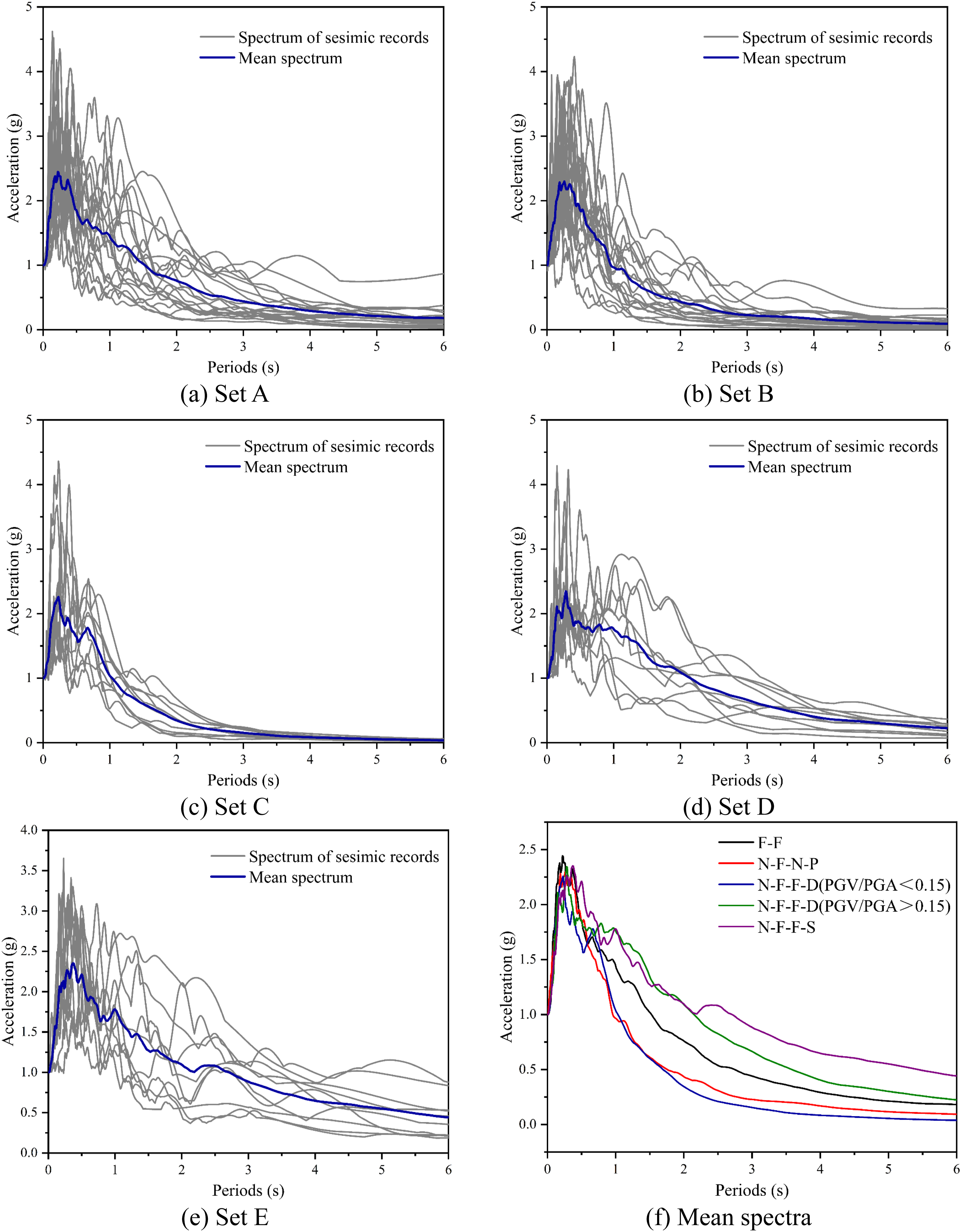
Furthermore, the seismic responses of structures are not only related to the type of earthquake ground motions but also significantly dependent on the pulse period of N-F earthquake ground motions. The influence of the pulse period on the structural response can be described by the ratio of the structural fundamental period to the pulse period (Alavi and Krawinkler, 2004; Sigurðsson et al., 2020). This study adopts the normalized period index (i.e., Acceleration response spectra of ground motions with different pulse periods.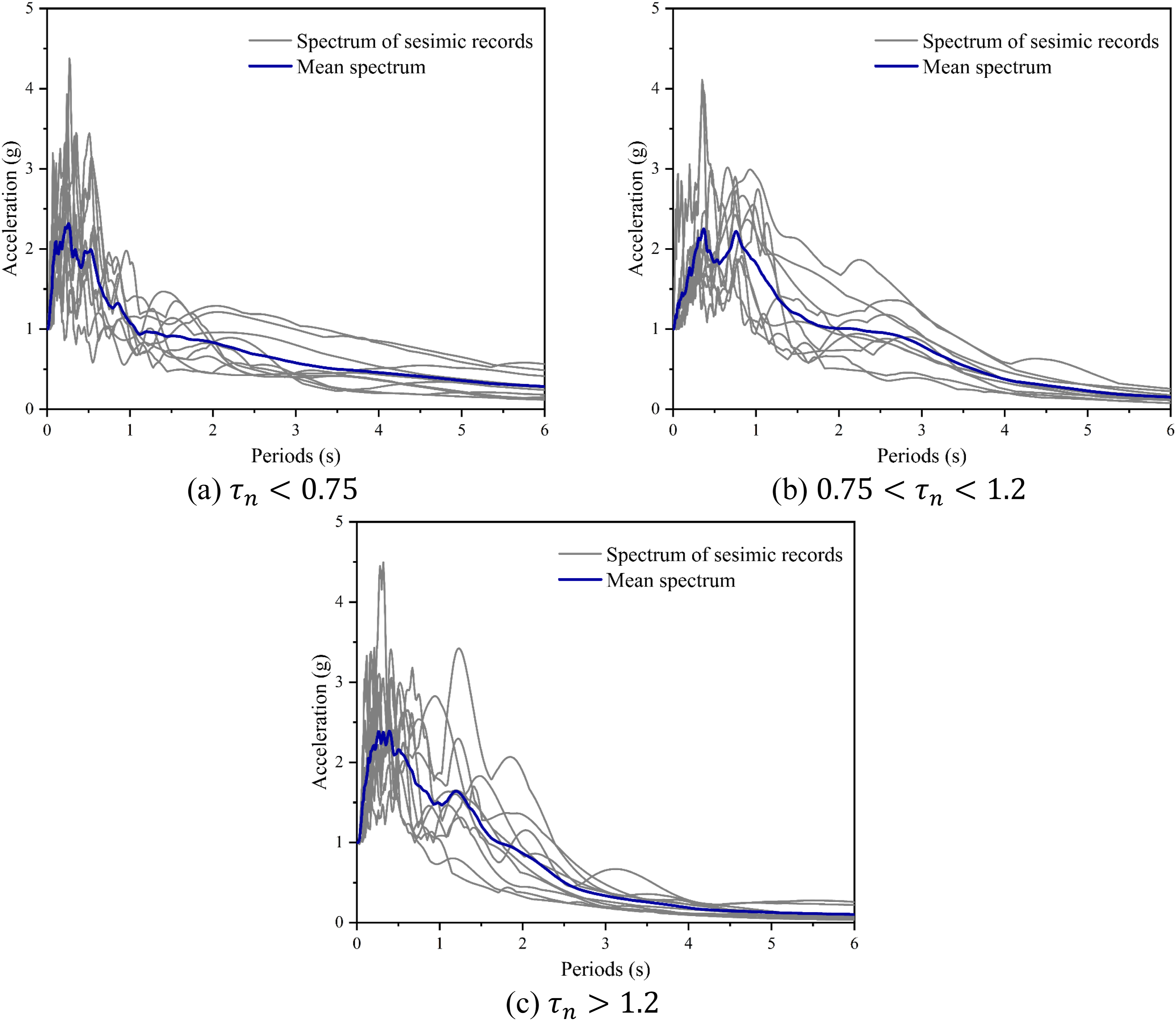
Results and discussion
The considered ground motions in the previous section are inputted to the tower base and the total simulation time is the same as the duration of each ground motion. Moreover, the calculation time step is set the same as the time interval of the recorded seismic ground motions. The influences of ground motion type, permanent ground displacement, and pulse period on the seismic responses of the wind turbine tower are discussed accordingly in this section.
Influence of ground motion types
Different types of earthquake ground motions.
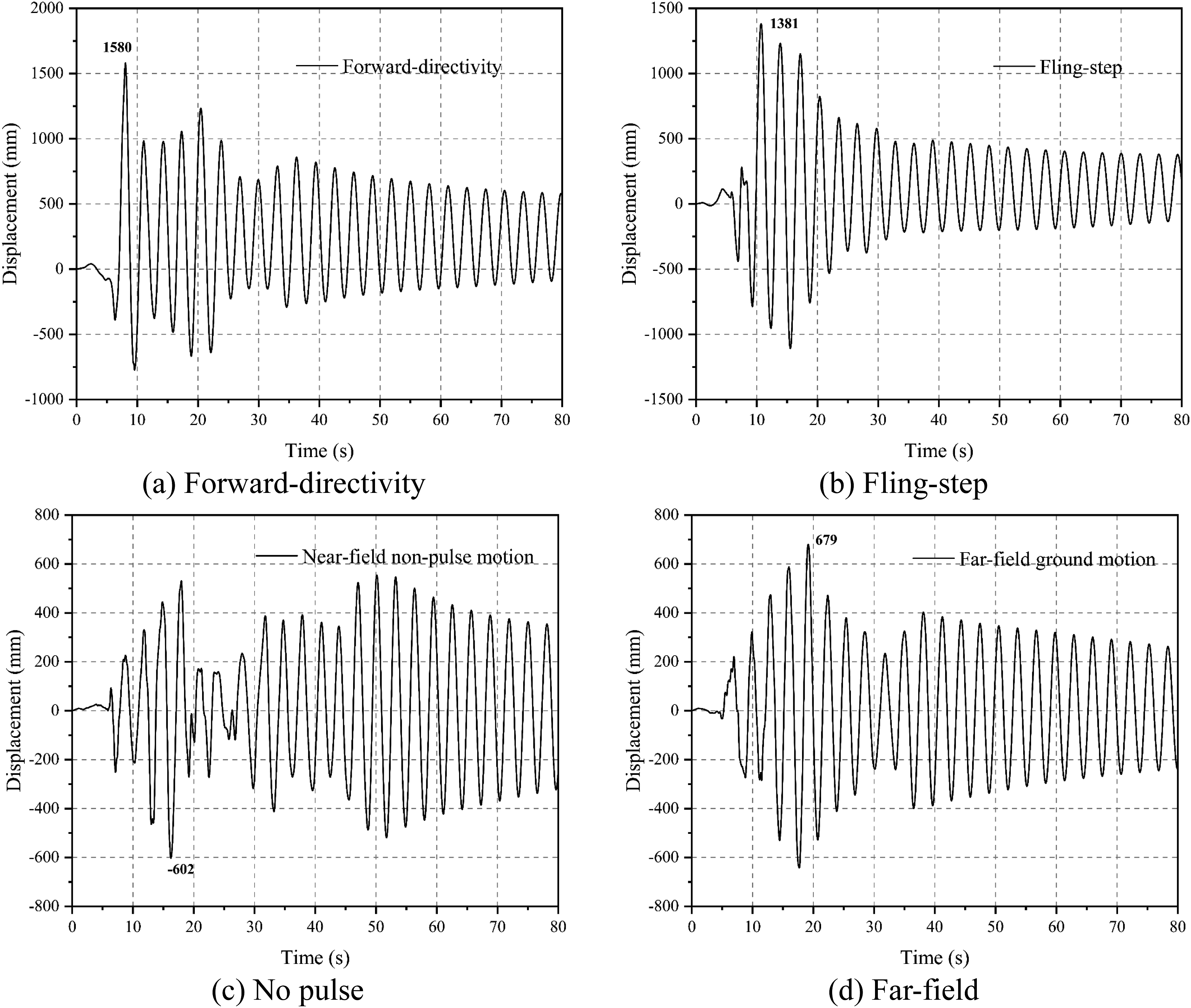
Tower top displacement time histories under different earthquake ground motions.
Furthermore, the residual displacements can be observed when the wind turbine is exposed to the N-F-F-D and N-F-F-S earthquake ground motions, while the tower vibrates around a mean displacement of zero under the N-F-N-P and F-F earthquake ground motions. This is because the maximum displacements are 1.58 m and 1.381 m under the N-F-P earthquake ground motions, which exceed the yield displacement of 1.34 m of the tower, indicating that the tower yields and plastic deformations occur. However, the maximum displacements under the N-F-N-P and F-F earthquake ground motions are smaller than the yield displacement, and the tower is in a linearly elastic state.
It needs to be reiterated that only four typical ground motions recorded in the same earthquake are used as the inputs to demonstrate the influence of ground motion types on the seismic responses of the wind turbine in Figure 12. To further investigate the influences of different ground motions recorded in different earthquake events on the seismic responses of the wind turbine, the fragility curves of the wind turbine tower under different ground motion types are also presented herein. Specifically, the PGA of the five different types of ground motions in Table A1 are scaled linearly from 0.1 g to 2.0 g, with an increment of 0.1 g and they are applied to the tower base, then the maximum response is recorded for each ground motion. Subsequently, five fragility curves corresponding to five different types of ground motions are generated and compared. Figure 13 shows the resulting fragility curves, illustrating the wind turbine’s failure probability under different damage states when subjected to various ground motion types. As shown in Figure 13, the damage probabilities for DS1-DS4 are consistent under the same ground motion type, i.e., the damage probability of DS1 is the largest, followed by DS2, DS3, and DS4. Taking F-F as an example, the likelihood of exceeding the four defined damage states is discussed as follows: (1) The rotation at the tower top is easy to happen, and the failure probability of DS1 is 99% when the PGA reaches 0.9 g. (2) When the PGA is less than 0.3 g, the damage probability of DS2 is near zero, indicating that the wind turbine is unlikely to experience DS2 under earthquake ground motions with PGA less than 0.3 g. However, with the PGA exceeding 0.3 g, the fragility curve of DS2 increases rapidly. (3) When the PGA is 1.2 g, the probabilities for DS2, DS3, and DS4 are 55%, 39%, and 17%, respectively. Additionally, Figure 13 also shows that regardless of the types of ground motion, the wind turbine is more prone to experiencing DS1 under low PGA conditions, such as PGA ≤0.2 g, while the damage probability of DS2-4 is near zero. Fragility curves of the wind turbine tower under different ground motion types.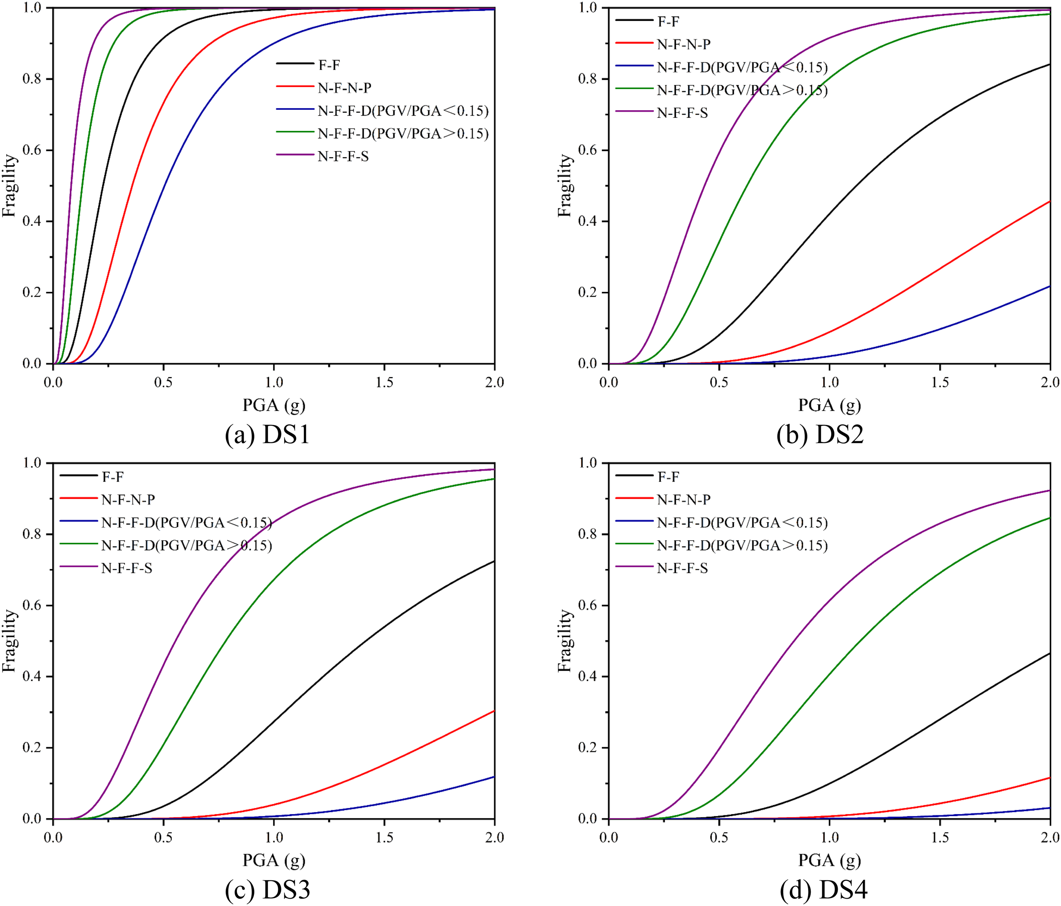
In terms of the influence of ground motion types, the fragility curve of N-F-F-S ground motions is the highest, followed by N-F-F-D (PGV/PGA >0.15), F-F, N-F-N-P, and N-F-F-D (PGV/PGA <0.15) earthquake ground motions. This can be explained by the mean acceleration response spectra presented in Figure 10(f) again. As shown in Figure 10(f), the order of the average response spectrum value at the fundamental period of the wind turbine (i.e., 3 s) from large to small is N-F-F-S earthquake ground motions, N-F-F-D (PGV/PGA >0.15) earthquake ground motions, F-F earthquake ground motions, N-F-N-P earthquake ground motions, and N-F-F-D (PGV/PGA <0.15) earthquake ground motions. It is concluded that the wind turbine response is the largest under the N-F-F-S earthquake ground motions. Moreover, the fragility curves of DS2-4 are more sensitive to the ground motion type than DS1.
More specifically, compared to N-F-N-P earthquake ground motions, the ground motion intensity required (or the damage probability) for DS1-4 is smaller (or larger) under F-F earthquake ground motions. For example, when the likelihood exceeding the threshold of DS1 is 50%, the PGAs are 0.36 g and 0.23 g for N-F-N-P and F-F earthquake ground motions, respectively. When the PGA reaches 1.5 g, the likelihood of DS2-4 for F-F ground motion is 69%, 54%, and 28%, respectively, which are 27%, 15%, and 4%, respectively, for N-F-N-P ground motions. The fragility curves of N-F-F-S are higher than F-F. When the PGA is 0.3 g, the failure probabilities of DS1-DS4 caused by N-F-F-S ground motion are 29%, 16%, 12%, and 5% larger than those caused by F-F ground motion, respectively, because of the sudden energy release and low structural damping. In addition, the probability of DS1-4 under N-F-F-D earthquake ground motions is dependent on the PGV/PGA ratio. As shown in Figure 13(c) and (d), when PGV/PGA >0.15, the probabilities of DS3 and DS4 under a PGA of 2 g are 96% and 85%, respectively, however, they are only 12% and 2% when PGV/PGA <0.15, indicating that less structural damage is caused by N-F-F-D earthquake ground motions with a small PGV/PGA ratio.
Influence of ground motion with different permanent ground displacements
To investigate the influence of permanent ground displacement amplitude on the seismic responses of the wind turbine, the assumed seismic motions with permanent ground displacements of 0 mm, 400 mm, 800 mm, and 1200 mm shown in Figure 9 are applied to the tower base, and Figure 14 shows the corresponding results. As shown, the responses of displacement are the same irrespective of the permanent ground displacement at the tower top. In other words, the responses of the wind turbine are governed by the dynamic component of the earthquake ground motion, and the quasi-static component has a negligible effect. Therefore, the fragility curves of the tower when exposed to seismic motions with different permanent ground displacements are not analysed and discussed. Displacement time histories at the tower top under seismic motions with various permanent ground displacements.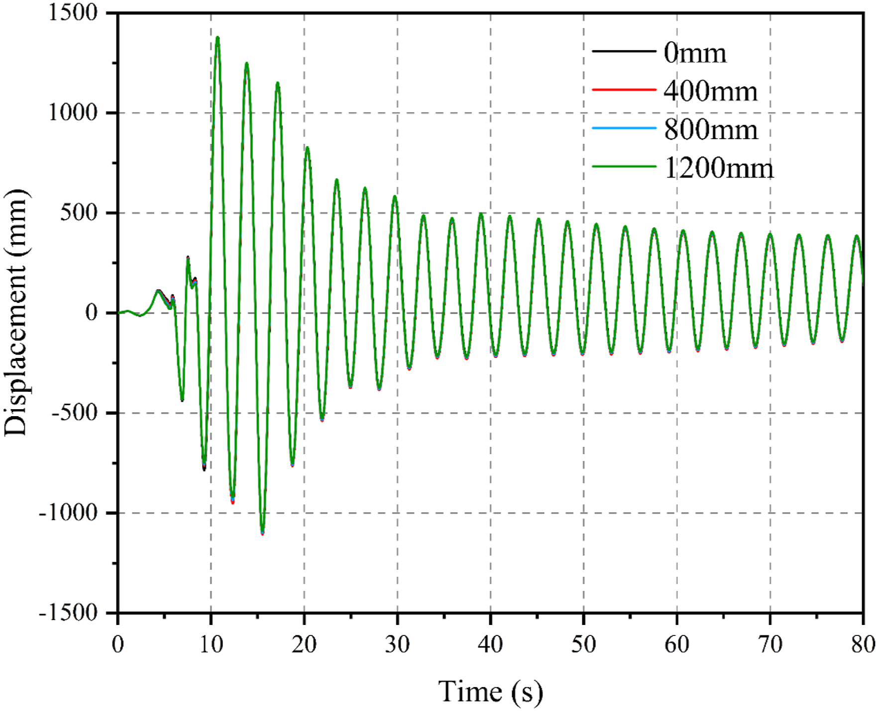
Influence of pulse period
To investigate the influence of the pulse period on the seismic responses of the wind turbine, the fragility curves of the tower under different pulse periods are presented herein. As mentioned before, three different ranges of the ratio between the structural fundamental period and the pulse period are considered in the present study, and these earthquake ground motions in Table A2 are used as external excitations. Figure 15 shows the resulting fragility curves of the tower under different damage states, specifically highlighting the influence of varying pulse periods. Fragility curves of the wind turbine tower under different pulse periods.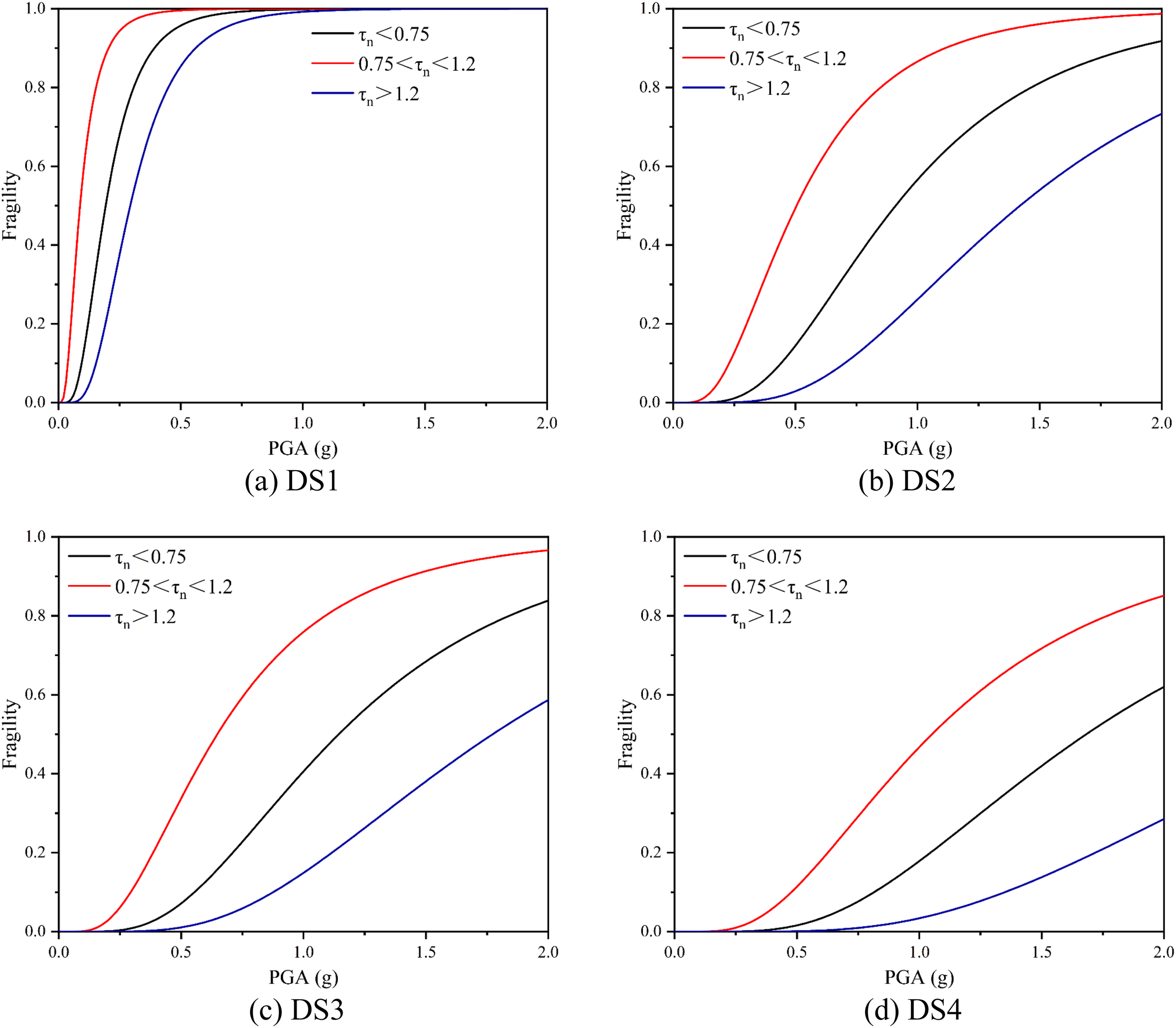
Similar to the influence of ground motion type, the influence of the pulse period on the fragility curves of DS1-DS4 is the same. Specifically, when
Conclusions
In this study, the seismic responses of the wind turbine are systematically investigated by considering the influences of earthquake ground motion type, permanent ground displacement, and pulse period. Four damage states are defined based on the SLS and ULS, and the seismic fragility curves of the tower are developed under different ground motion types and pulse periods. The main conclusions are summarized as follows: (1) Compared to F-F and N-F-N-P earthquake ground motions, the wind turbine experiences larger responses when subjected to the N-F earthquake ground motions with pulses due to the sudden energy release. In this study, the wind turbine tower even undergoes yielding under these conditions. However, the effect of the permanent ground displacement on the seismic responses of the wind turbine is minimal. (2) When PGA is fixed, the probability of failure decreases as the damage level increases. In other words, during an earthquake, the top of the wind turbine tower is likely to undergo excessive rotation, which could lead to a collision between the blades and the tower. In addition, excessive displacement can damage the tower. However, the likelihood of yielding and buckling is relatively low. (3) The probability of the wind turbine exceeding its predetermined damage states varies significantly with different types of ground motions and PGV/PGA ratios. N-F-F-S and N-F-F-D ground motions with high PGV/PGA result in larger seismic responses of the wind turbine, increasing its vulnerability to failure. (4) The fragility of the tower is also affected by the pulse period. When the pulse period is close to the fundamental period of the wind turbine, structural resonance can occur, resulting in larger structural responses and a higher probability of damage. (5) The type of ground motion and pulse period have a more significant effect on the displacement response at the top of the wind turbine tower, while their effect on the rotation at the top of the tower is relatively minor.
This paper selects PGA as the
Supplemental Material
Supplemental Material - Influence of earthquake ground motion types on the seismic responses of wind turbines
Supplemental Material for Influence of earthquake ground motion types on the seismic responses of wind turbines by Yufeng Yuan, Kaiming Bi and Haoran Zuo in Advances in Structural Engineering.
Footnotes
Acknowledgments
The authors would like to acknowledge the support from Guangdong Basic and Applied Basic Research Foundation (No. 2023B1515250002) and Australian Research Council Discovery Early Career Researcher Award (DE250100236) for carrying out this research.
Declaration of conflicting interests
The author(s) declared no potential conflicts of interest with respect to the research, authorship, and/or publication of this article.
Funding
The author(s) disclosed receipt of the following financial support for the research, authorship, and/or publication of this article: This work was supported by the Guangdong Basic and Applied Basic Research Foundation (No. 2023B1515250002) and the Australian Research Council Discovery Early Career Researcher Award (DE250100236) for carrying out this research.
Supplemental Material
Supplemental material for this article is available online.
References
Supplementary Material
Please find the following supplemental material available below.
For Open Access articles published under a Creative Commons License, all supplemental material carries the same license as the article it is associated with.
For non-Open Access articles published, all supplemental material carries a non-exclusive license, and permission requests for re-use of supplemental material or any part of supplemental material shall be sent directly to the copyright owner as specified in the copyright notice associated with the article.