




Abstract
The bending moment resistance of cold-formed steel channels can be improved by combining two channel sections with a pair of screw fasteners in the webs spaced intermediately along the member. By combining the two channels in this way, the moment capacity of the beam can be increased beyond the capacity of two single channels. Another advantage of this type of section is the coincidence of the centroid and shear centre which reduces the effects of stresses due to eccentric load and torsion. Most research on back-to-back channels in bending has focused on local and distortional buckling while data on flexural-torsional buckling is scarce. The flexural-torsional buckling resistance of a beam depends on various section properties which include the minor axis second moment of area, and the torsion and warping constants of the section. Although the flexural-torsional buckling moment can be easily determined for a single channel section because these section properties are relatively straightforward to calculate, the calculation of the flexural-torsional buckling moment for back-to-back channels with intermediately spaced screw fasteners is much more complicated due to the discontinuity of the cross-section along the length of the beam. In this paper, the shear stiffness of the screw fasteners connecting the channels is obtained from test results. The shear stiffness is then used to model the screw fasteners in a finite element analysis to analyse a beam composed of back-to-back channels under bending and torsion. The results are compared with two single channel sections and with back-to-back channels assuming full composite action. The effect of different screw fastener spacings is also investigated. Simple relationships between the bending and torsion section properties for single channels and back-to-back channels are presented. Suggestions for the design of back-to-back channels in bending are also proposed.
Keywords
Introduction
Background
The bending moment resistance of cold-formed steel channels can be improved by combining two channel sections with a pair of screw fasteners in the webs spaced intermediately along the member, as shown in Figure 1. By combining the two channels in this way, the moment capacity of the beam can be increased beyond the capacity of two single channels. Another advantage of back-to-back channel sections is the coincidence of the centroid and shear centre which reduces the effects of stresses due to eccentric load and torsion. Back-to-back channels with screw fasteners through the webs.
Because of their thin plate elements, cold-formed steel structures are prone to buckling. The types of buckling modes include local buckling, distortional buckling, flexural-torsional buckling and combinations of these modes. Local and distortional buckling are the predominant buckling modes in braced beams while long unbraced beams are more susceptible to flexural-torsional buckling. Figure 2 shows these three buckling modes for back-to-back channels under bending moment. Buckling modes of back-to-back channels under bending moment.
When a beam is bent about the major axis, it may undergo flexural-torsional buckling by bending about the minor axis and twisting, as shown in Figure 2. Therefore, the elastic flexural-torsional buckling moment of beams depends on the minor axis second moment of area I y , torsional constant J and warping constant I w . Although these section properties can be easily determined for a single channel, their calculation for back-to-back channels with intermediate screw fasteners is much more complicated because the screw fasteners cause a discontinuity of the cross-section along the length of the beam. The presence of intermediately spaced screw fasteners in back-to-back channels leads to the effect known as partial composite action. If the back-to-back channels are welded along their full length, the abutting surfaces of the webs will undergo the same strain and full composite action is achieved. Conversely, if the channels are not connected at all, they bend as individual sections and there is no composite action. Between these two limiting cases, for most types of screw fasteners the back-to-back channels undergo relative longitudinal (shear) displacements at the fastener points and develop shear forces in the screw fasteners. In this case, the sections display partial composite action and the elastic flexural-torsional buckling moment lies somewhere between the limiting cases of full and no composite action.
Literature review
Although there has been substantial research on the flexural-torsion buckling of single cold-formed steel sections (Hancock, 2022; Yu and LaBoube, 2010), to the authors knowledge research on the flexural-torsional buckling of back-to-back cold-formed steel channels in bending is limited to only a few studies. Manikandan and Thulasi (2019) conducted tests and finite element analysis to investigate the bending strength of screw fastened back-to-back plain lipped channels and back-to-back channels with web and return lip stiffeners and found that the channels with the extra stiffeners had a higher moment capacity. Fitrah and Melinda (2020) performed bending tests on screw fastened back-to-back channels with different thicknesses and observed local buckling and flexural-torsional buckling failure modes. Roy et al. (2021) conducted an experimental and numerical investigation on screw fastened back-to-back channels subjected to four-point bending and concluded that the current direct strength method (DSM) design equations are conservative if the flexural capacity of a single channel is simply doubled to obtain the flexural capacity for back-to-back channels. Ungureanu et al. (2022) conducted tests on bolted back-to-back plain and lipped channels and observed that at long spans failure occurred by interaction of local and flexural-torsional buckling.
Research on back-to-back channels in bending has mainly focused on local and distortional buckling. Zhou and Shi (2011) investigated the flexural strength of back-to-back channels through testing and finite element analysis. Based on their results, they derived a new effective width method and strength-reduction method for the ultimate moment capacity. Laim et al. (2013) conducted an experimental and numerical investigation on single, back-to-back and boxed channels and found that the strength-to-weight ratio of back-to-back channels is superior to that of single channels. Wang and Young (2018) conducted an experimental and numerical investigation on the local and distortional buckling of back-to-back and boxed channels with different screw arrangements in the web. They found that the screw arrangement in the web had little influence on the moment capacity but the spacing of the screws along the beam was more significant. Ye et al. (2018, 2019) also studied the local and distortional buckling of back-to-back channels and concluded that the current DSM design equations are adequate for these failure modes. Dar et al. (2019) conducted bending tests on back-to-back channels bolted together through the webs and found that an increase in strength can be achieved by welding an angle section to the inside of the lip in the compression flange. Ghannam (2019) studied the bending strength of back-to-back channels using finite element analysis and concluded that both the EWM and DSM are conservative for back-to-back channels. Lukacevic et al. (2021) used a non-linear finite element analysis to study the local and global buckling resistance of back-to-back channels with different connections and concluded that the bending capacity is highly affected by the type of connection. Sujitha et al. (2022) investigated the bending behaviour of back-to-back and boxed channels with web stiffeners by testing and finite element analysis.
The behaviour of screw fasteners under shear has a major influence on the behaviour of built-up members and so this has also received considerable attention from researchers. These studies generally involved tests on screw fastener connections to determine the initial shear stiffness of the screw fasteners and/or the ultimate capacity of the connection. Such tests have been performed by Rogers and Hancock (1999), LaBoube and Sokol (2002), Casafont et al. (2006), Serrette and Peyton (2009), Francka and LaBoube (2010), Moen et al. (2014), Pham and Moen (2015), Phan and Rasmussen (2018), Huynh et al. (2018) and Roy et al. (2019). Finite element modelling has also been used to investigate the behaviour of screw fastened connections by Roy et al. (2019), Huynh et al. (2020), Kalo and Peterman (2020) and Quan et al. (2021).
Experimental, numerical and analytical methods were employed by Phan and Rasmussen (2019) to study the minor axis flexural rigidity of back-to-back channel sections. Mechanics-based solutions for the bending, torsion and buckling of built-up sections have been derived by Rasmussen et al. (2020). The results from these investigations show that the effective minor axis second moment of area I y,eff for beams with screw fasteners lies between the values for full and no composite action. The uniform torsion analysis showed that there is no shear deformation induced in the fasteners and therefore the effective torsion constant J eff is equal to the value for no composite action. Although there were no definitive results for the warping constant, it was conservatively suggested that the ratio of the effective value of the warping constant I w,eff to the full composite value be equal to that for I y until further research proves otherwise.
Flexural-torsional buckling
For a simply supported beam subjected to equal and opposite end moments as shown in Figure 3, the theoretical elastic flexural-torsional buckling moment M
b
is given by (Trahair, 1993) Beam in uniform bending.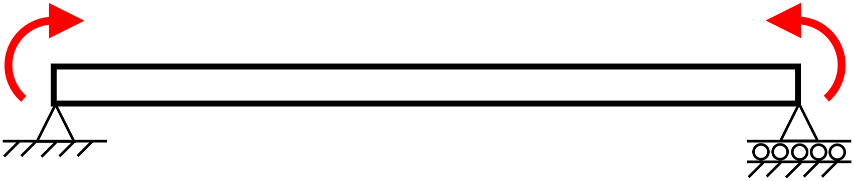

Bending
For a beam subjected to equal and opposite end moments, the maximum deflection δ in the beam occurs at mid-span and can be calculated as (Timoshenko, 2004)

Uniform torsion
When a beam is subjected to a pair of equal and opposite end torques T and the ends are free to warp as shown in Figure 4, the rate of change of the angle of twist rotation is constant along the beam and the beam is in a state of uniform torsion. The relationship between the torsion constant J and angle of twist rotation ϕ is given by (Trahair and Bradford, 1998). Beam in uniform torsion.

Non-uniform torsion
When a cantilever beam which is fixed at one end is subjected to a torque T at the free end as shown in Figure 5, the rate of change of the angle of twist rotation varies along the beam and the beam is in a state of non-uniform torsion. The relationship between the torsion constant J, warping constant I
w
and angle of twist rotation ϕ at the free end is given by (Trahair and Bradford, 1998). Beam in non-uniform torsion.


Research objectives
The elastic flexural-torsional buckling moment for a beam is used in many design standards as the basis for determining the flexural-torsional buckling moment capacity for beams with different moment distributions, restraints and load height. Thus, the elastic flexural-torsional buckling moment is a very important quantity for designers of cold-formed steel beams. The calculation of the elastic flexural-torsional buckling moment is a simple procedure for single sections where I y , J and I w can be easily calculated by computer programs such as THIN-WALL-2 (Nguyen et al., 2015; Papangelis and Hancock, 1995) and CUFSM (Schafer and Adany, 2006). However, the calculation of these section properties for back-to-back channels is more difficult and so structural designers are in need of guidance to determine the elastic flexural-torsional buckling moment.
In this paper, the bending, torsion and flexural-torsional buckling behaviour of back-to-back channels is investigated. First, the shear stiffness of the screw fasteners connecting the channels is obtained from test results. The shear stiffness is then used to model the screw fasteners in a finite element analysis for the bending, torsion and flexural-torsional buckling of back-to-back channels. The results are compared with two single channel sections and with back-to-back channels assuming full composite action. The effect of different screw fastener spacings is also investigated. Simple relationships between the bending and torsion section properties for single channels and back-to-back channels are presented. Suggestions for the design of back-to-back channels in bending are also proposed.
Finite element model
General
The commercial finite element analysis program Strand7 (Strand7 Pty Ltd, 2024) was used to analyse the back-to-back channel beams under bending, uniform torsion and non-uniform torsion. The back-to-back channel sections were modelled using 4-node shell elements which were developed for Strand7 based on the thin shell theory described by Jetteur and Frey (1986). Each node has six degrees of freedom comprising of translational displacements along the horizontal X, vertical Y and longitudinal Z axes and rotational displacements about the X, Y and Z axes. A convergence study for a 203 mm deep channel showed that a mesh size of approximately 5 × 5 mm was sufficient to give an accurate result. The screw fasteners were modelled as short solid cylindrical beam elements positioned between adjacent nodes on the two webs. The complete finite element model of a back-to-back channel beam subjected to equal and opposite end moments is shown in Figure 6. All the beams analysed in this study have a length of 5 metres. Finite element model of back-to-back channels in uniform bending.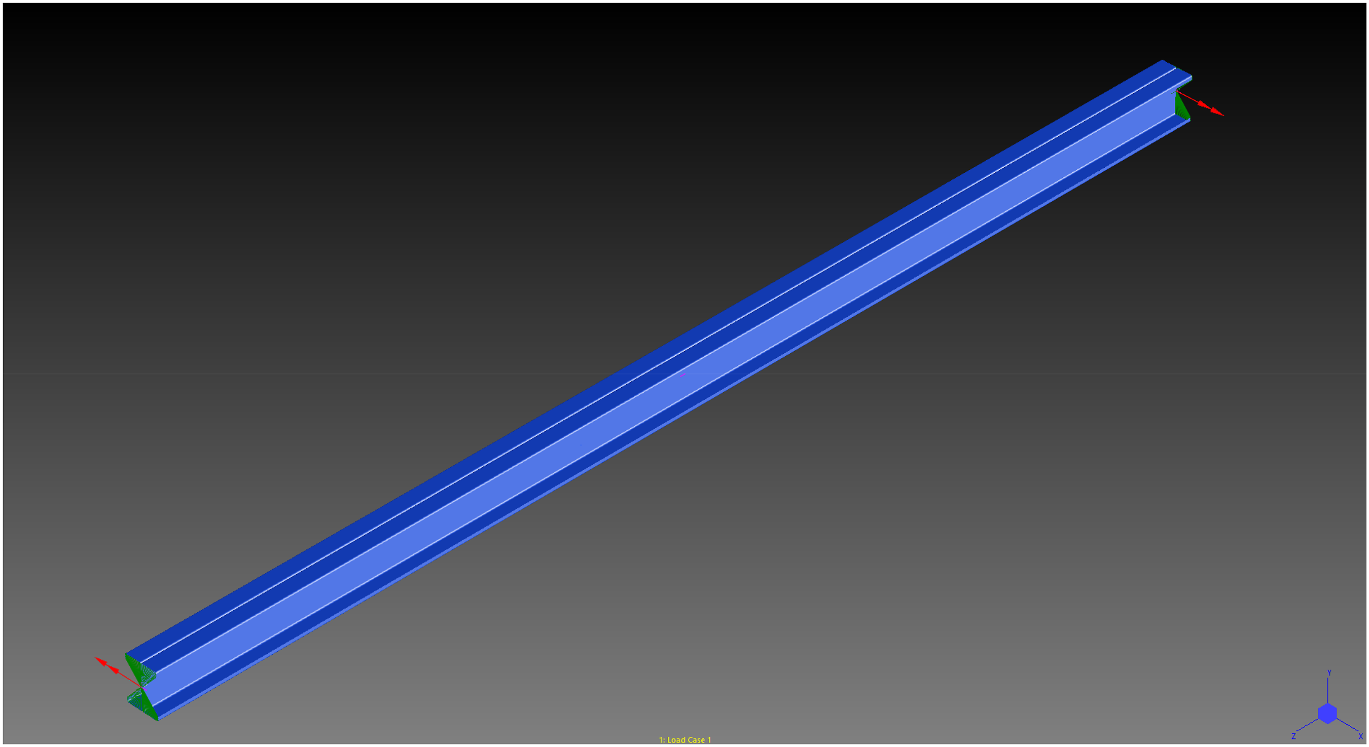
In order to calculate the elastic flexural-torsional buckling moment of the back-to-back channels, a

The deformations from the finite element linear static analysis are used in the theoretical equations to calculate the effective section properties for bending and torsion. The deflection from the minor axis bending analysis is used to calculate the effective minor axis second moment of area I y,eff from equation (2). The twist rotation from the uniform torsion analysis is used to calculate the effective torsion constant J eff from equation (3). The twist rotation from the non-uniform torsion analysis is used to calculate the effective warping constant I w,eff from equation (4).
It should be noted that the finite element analyses in this study are all linear because the aim of this research was to calculate the elastic flexural-torsional buckling moment and section properties for back-to-back channels. Therefore, initial geometric imperfections, residual stresses and stress-strain curves are not required. These parameters are only required if a geometric and material non-linear analysis is to be performed. Furthermore, a reliability analysis is not required as this type of analysis is only performed when ultimate moments obtained from either test results or non-linear analysis are to be compared with design equations. In this study, ultimate moments are not calculated, only elastic buckling moments.
Loading and boundary conditions
For the channels in bending, in order to allow each channel to displace in the longitudinal direction independently of the other channel, half of the end moment was applied to each channel by using an interpolated multi-point link (MPL) to distribute the moment to multiple nodes around the section, as shown in Figure 7. In Strand7, an interpolated MPL is a useful way to apply load to many locations from a single point without influencing the stiffness of the structure. The beam is simply supported which means displacements in the X and Y directions and rotation about the Z axis are restrained at both ends. The displacement in the Z direction is restrained at mid-span to prevent rigid body displacement of the beam in the longitudinal direction. Moment about minor axis applied to each channel using interpolated multi-point links.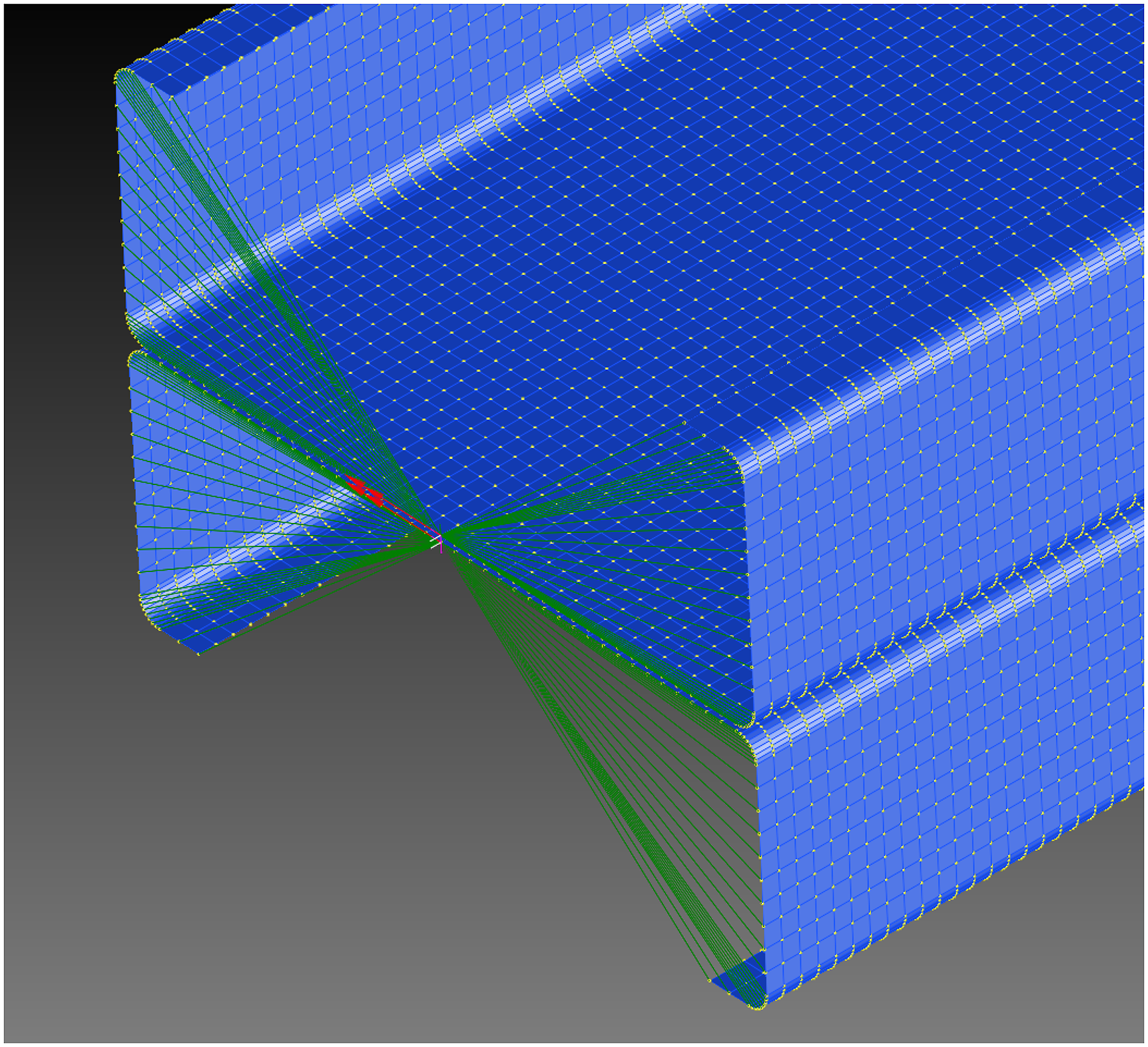
For the channels in torsion, a torque is applied to the centroid at one end using rigid links which transfer the torque to the whole cross-section, as shown in Figure 8. The rigid links provide rigidity in the XY plane to prevent distortion of the cross-section while simultaneously allowing the ends to warp. The centroid is also restrained from displacing in the X and Y directions at this end. For uniform torsion, at the other end of the beam the displacements of the centroid in all three directions and rotation about the Z axis are restrained. For non-uniform torsion, the beam is built-in at the other end to simulate a cantilever beam. Torque applied to channels using rigid links.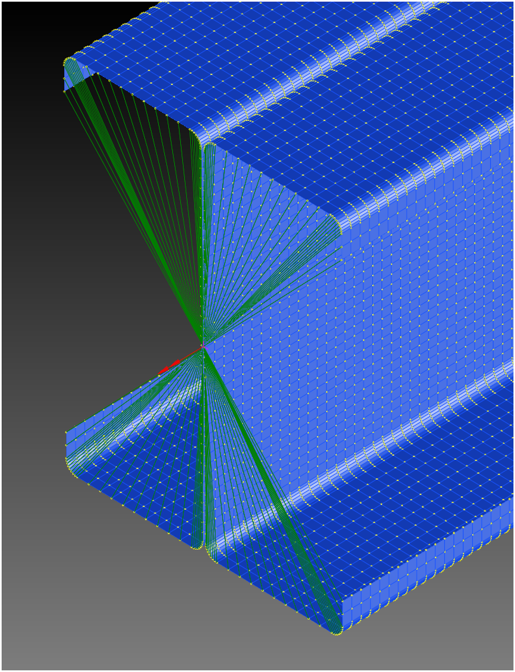
Section dimensions
Dimensions of Channels.
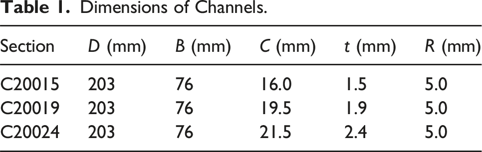
It is seen in Table 1 that the thinnest section is 1.5 mm even though thinner sections are available. The reason that thinner sections are not included is because they did not exhibit a pure flexural-torsional buckling mode in the finite element analysis. Instead, these thinner sections buckled in a mode which involves both flexural-torsional buckling and local buckling of the top flanges and web. Only the sections in Table 1 were analysed because these sections buckled in a pure flexural-torsional mode.
Material properties
The material properties of the channel sections include the elastic modulus E = 200,000 MPa and Poisson’s ratio ν = 0.3. These are the recommended values given in AS/NZS 4600 (Standards Australia/Standards New Zealand, 2018). The shear modulus G is calculated as (Timoshenko and Gere, 1961).
Screw fastener spacings
Screw Fastener Spacings.

Validation of finite element model
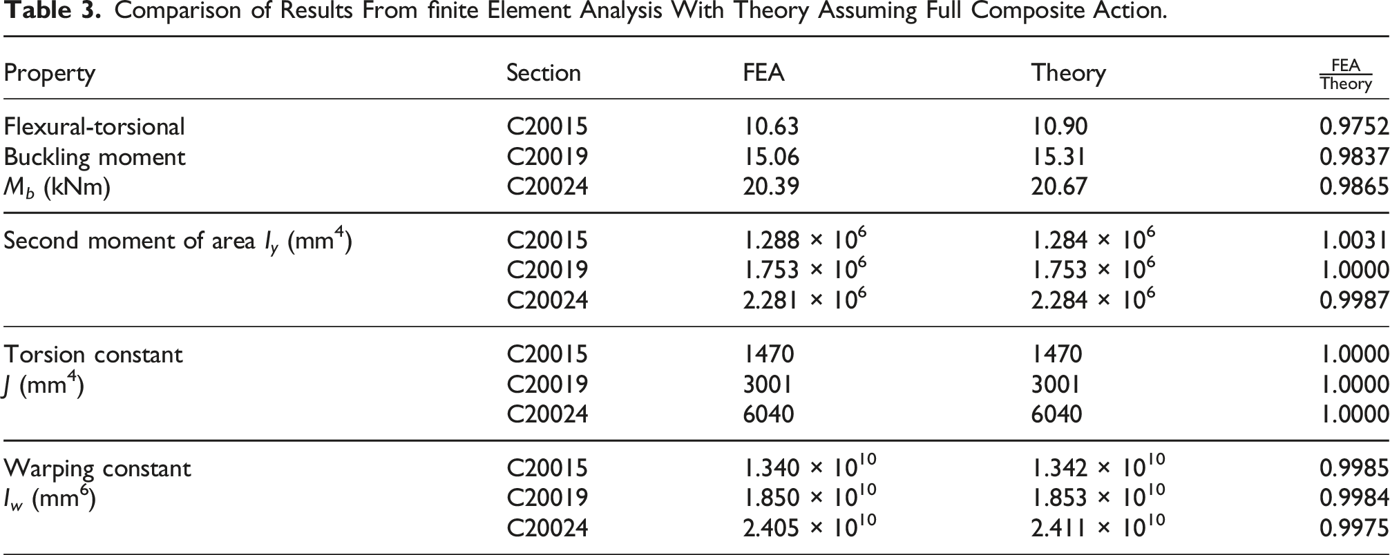
The finite element model described in the previous sections can be used to calculate the elastic flexural-torsional buckling moment for back-to-back channels by using the linear buckling analysis in Strand7. The finite element model can also be used to calculate the section properties (I y , J, I w ) by substituting the maximum deflection or twist rotation from the finite element linear static analysis in the theoretical Equations (2)–(4).
Theoretical values for the section properties of back-to-back channels assuming full composite action can be calculated by the program THIN-WALL-2. These section properties can be used to calculate the theoretical value for the elastic flexural-torsional buckling moment using equation (1). Hence, the validity of the finite element model can be checked by analysing the channels in Table 1 as back-to-back sections assuming full composite action and comparing the results with the theoretical values.
Comparison of Results From finite Element Analysis With Theory Assuming Full Composite Action.
Screw fasteners
Behaviour of screw fasteners
The response of built-up cold-formed steel members to loading very much depends on the behaviour of the screw fasteners used to connect the different sections. As back-to-back channels buckle laterally and undergo minor axis bending and torsion, the individual channels move relative to each other and the screw fasteners undergo substantial tilting and associated shear deformation (Rasmussen et al., 2020). Hence, back-to-back channels with screw fasteners are very much susceptible to partial composite action. A typical load-displacement curve for a screw fastener in shear is shown in Figure 9. This curve displays an initial linear-elastic range followed by yielding and non-linear behaviour up to the ultimate shear capacity and then an extensive post-ultimate response which is associated with screw tilting. Typical load-displacement curve for screw fastener in shear.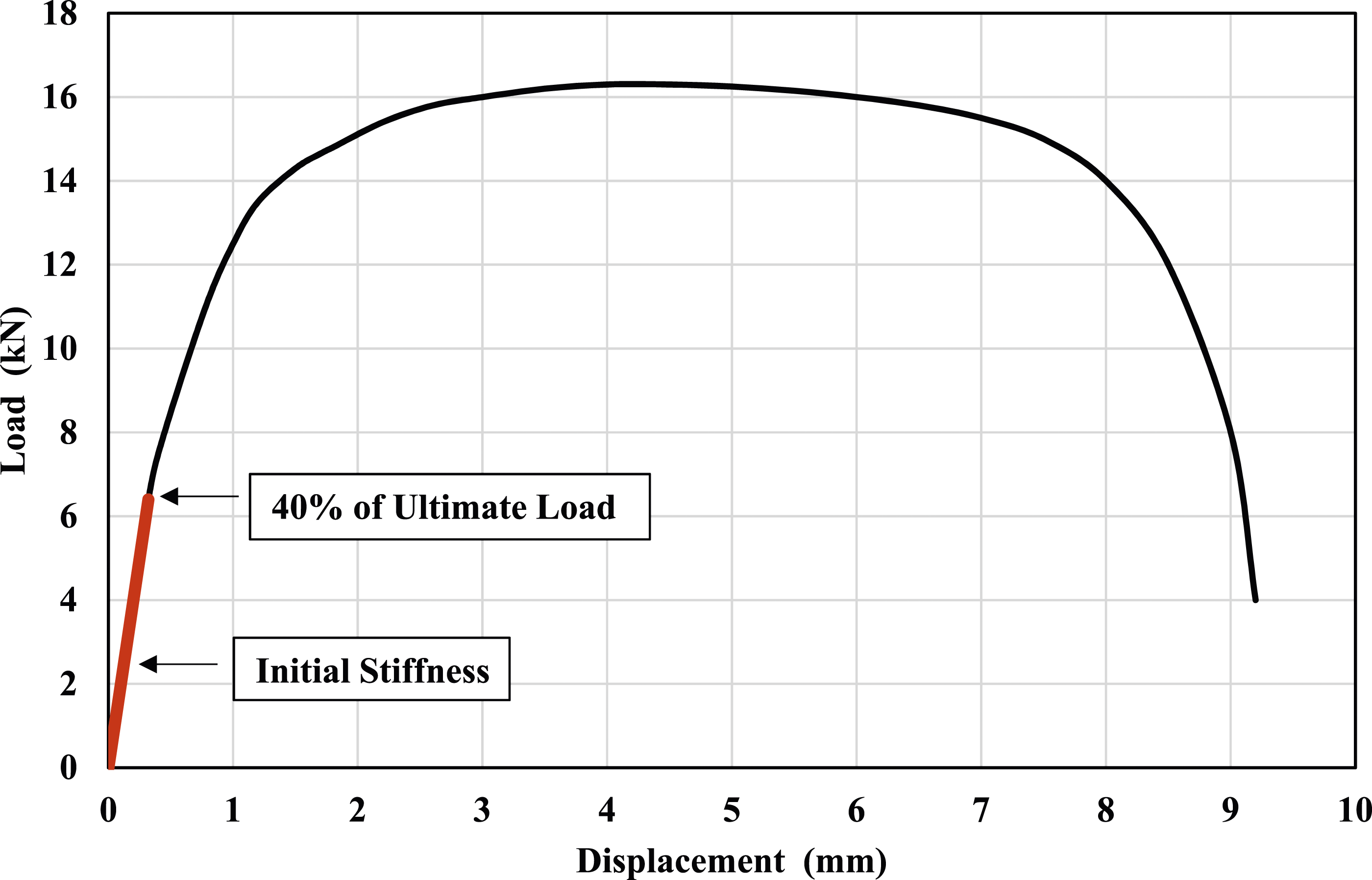
Screw fastener tests
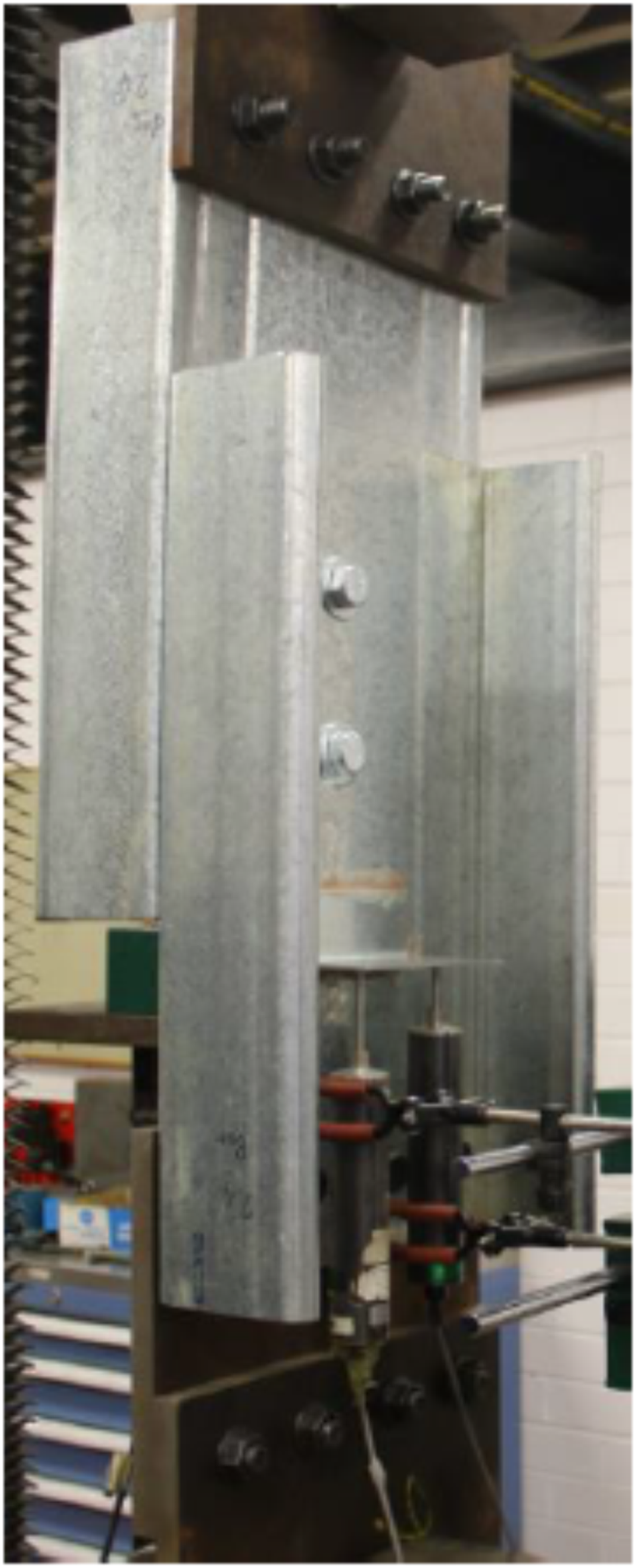
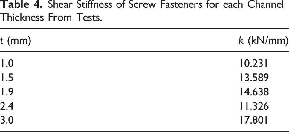
An accurate value of the shear stiffness k of the screw fasteners is essential in order to perform a reliable numerical investigation of the behaviour of built-up cold-formed steel members. The shear stiffness of the screw fasteners can be determined from a standard test method described in AISI S905 (American Iron and Steel Institute, 2013). This test method was used by the authors colleagues Phan and Rasmussen (2018) to determine the initial shear stiffness of screw fasteners connecting two back-to-back cold-formed steel channels of the same thickness. Figure 10 shows a drawing of the test arrangement and a photo is shown in Figure 11. Each channel is 500 mm long and the channels overlap each other by 300 mm. The channels are connected by two rows of screw fasteners spaced 100 mm apart. Five cold-formed steel channels were tested with thickness of 1.0, 1.5, 1.9, 2.4 and 3.0 mm. Screw fasteners of 6.3 mm diameter were used for the channel thicknesses of 1.0, 1.5 and 1.9 mm and 5.5 mm diameter screw fasteners were used for the channel thicknesses of 2.4 and 3.0 mm. Drawing of connection test. Photo of connection test (Phan and Rasmussen, 2018).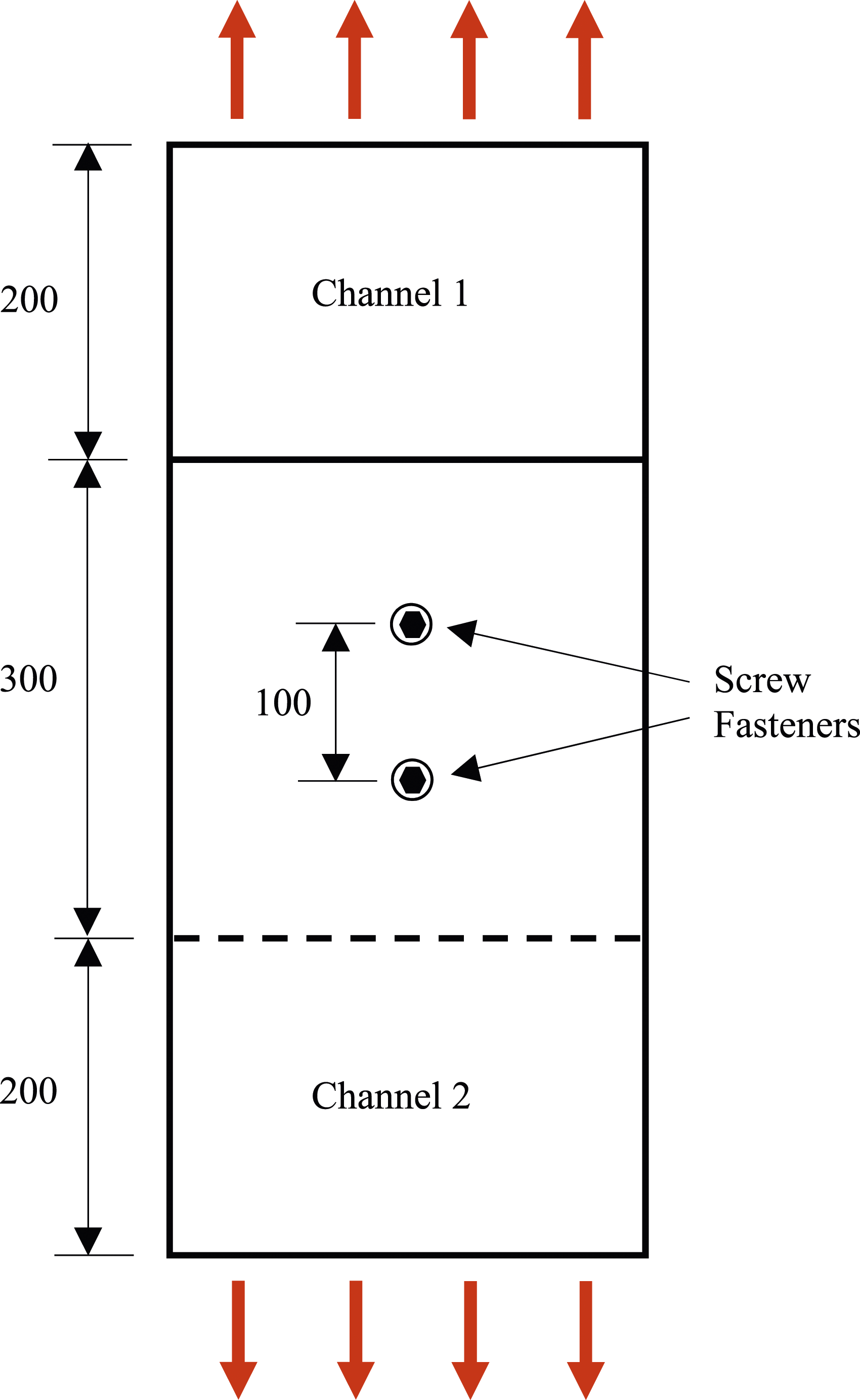
Shear Stiffness of Screw Fasteners for each Channel Thickness From Tests.
Modelling of screw fasteners
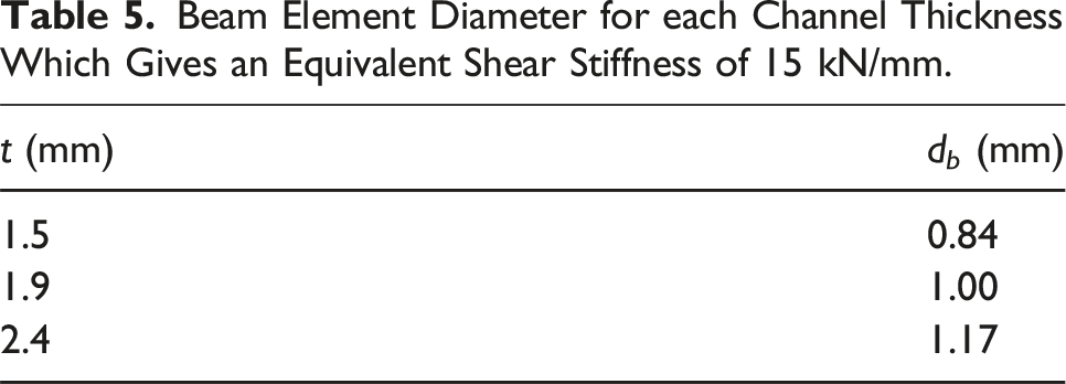
As mentioned earlier, in the finite element analysis of this study the screw fasteners are modelled as short solid cylindrical beam elements, as shown in Figure 12. These beam elements must have a diameter which gives the beam elements a shear stiffness equivalent to that determined from the tests. An appropriate diameter d
b
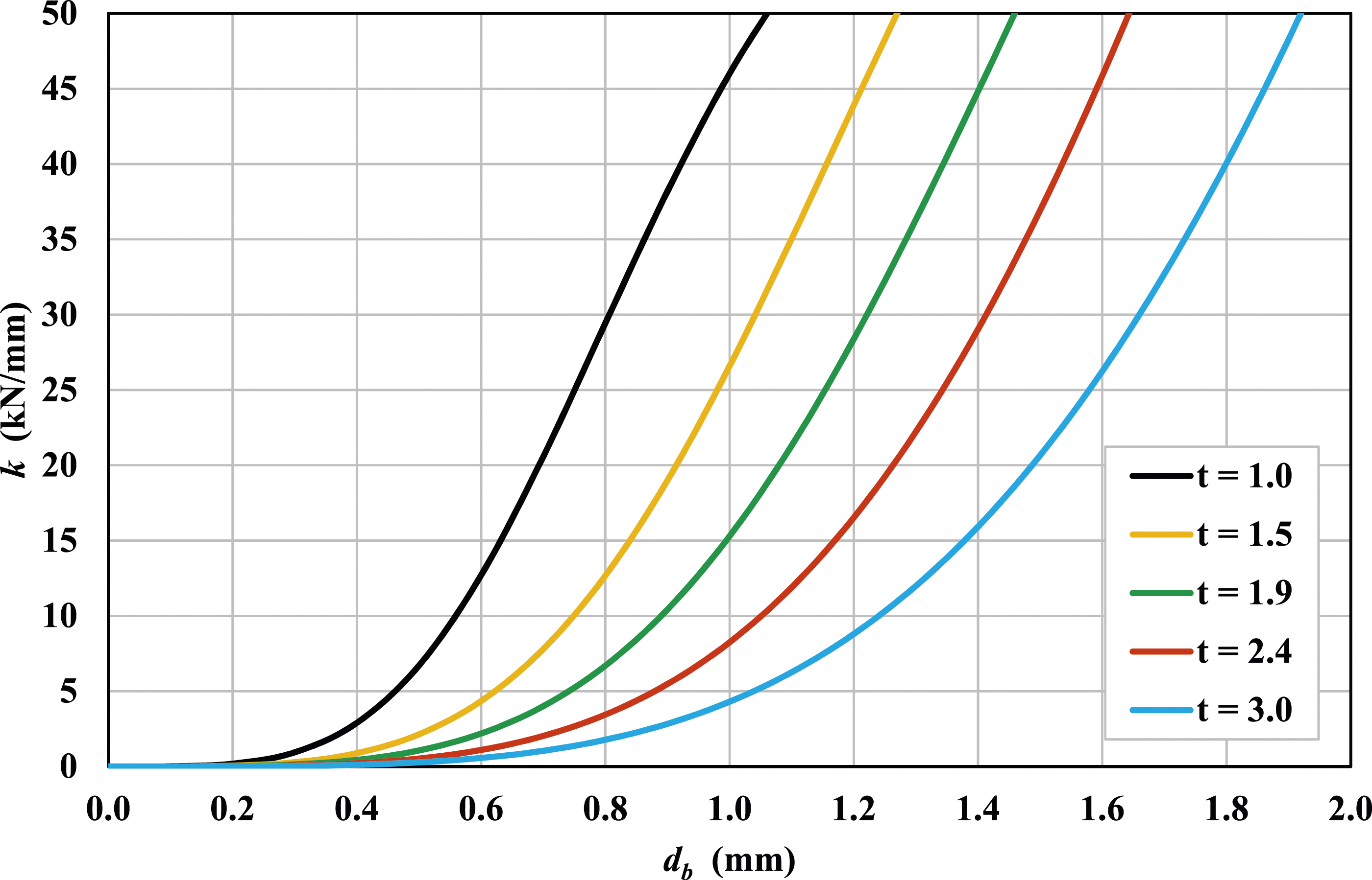
for the beam elements can be calculated from a finite element linear static analysis of a simple model of the test arrangement, as shown in Figure 13. Using this simple model, the graph shown in Figure 14 can be created which shows the variation of the shear stiffness k with d
b
for each channel thickness t. Thus, for example, if a screw fastener shear stiffness of 15 kN/mm is to be used for a 1.9 mm thick channel, the appropriate diameter for the beam elements in the finite element analysis can be obtained from the graph as 1.0 mm. Short solid cylindrical beam element used to model screw fastener. Simple finite element model of connection tests. Shear stiffness for different diameters of solid cylindrical beam element for different channel thicknesses.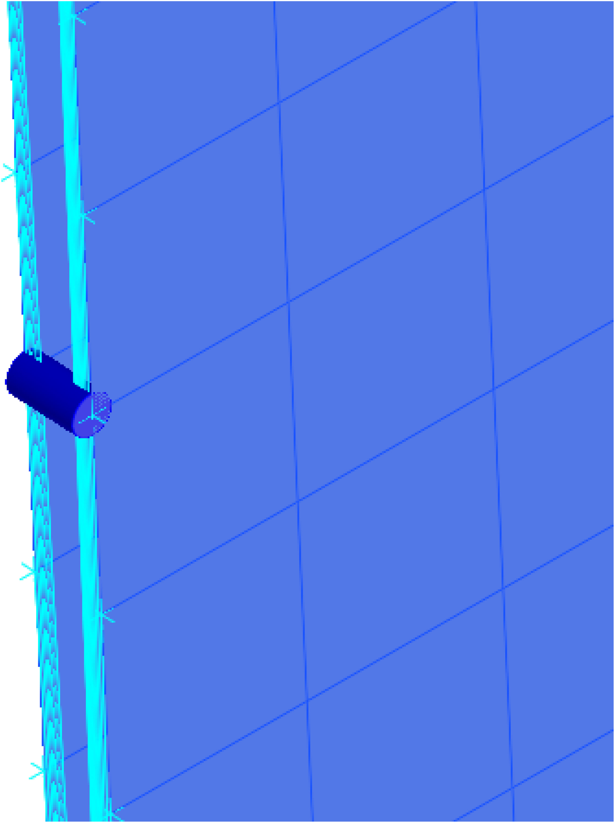

Beam Element Diameter for each Channel Thickness Which Gives an Equivalent Shear Stiffness of 15 kN/mm.
Results and discussion
Elastic flexural-torsional buckling moment
Using the values of d
b
in Table 5 for each channel thickness, a linear buckling analysis in Strand7 was performed for each 5 metre long back-to-back channel subjected to equal and opposite end moments about the major X axis. The screw fastener spacings s ranged from 50 mm (s/L = 0.01) to 2,500 mm (s/L = 0.5), as shown in Table 2. Figure 15 shows the variation of the elastic flexural-torsional buckling moment from the finite element analysis M
eff
normalised with double the elastic flexural-torsional buckling moment for a single channel 2M with the screw fastener spacing ratio s/L. Figure 16 displays a typical buckled shape for back-to-back channels with screw fasteners. Variation of elastic flexural-torsional buckling moment with screw fastener spacing. Typical buckled shape from finite element analysis (C20015 with s/L = 0.2).
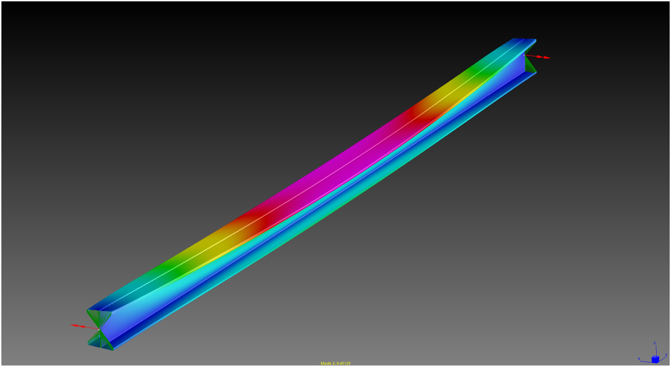
The beneficial effect of combining two channels back-to-back is clearly seen in Figure 15 where the elastic flexural-torsional buckling moment for back-to-back channels is significantly higher than double the elastic flexural-torsional buckling moment for a single channel. Figure 15 shows that the elastic flexural-torsional buckling moment gradually increases as the spacing between the screw fasteners is reduced. It should also be noted that only a few screw fasteners are required to gain a significant increase in the elastic flexural-torsional buckling moment. For example, even just one pair of screw fasteners placed at mid-span (s/L = 0.5) can lead to a substantial increase in the elastic flexural-torsional buckling moment by a factor of 1.45-1.51 times the value for two single channels. When the screw fasteners are spaced closer together (s/L = 0.1), the elastic flexural-torsional buckling moment increases by a factor of 1.58-1.64 times the value for two single channels.
Also shown in Figure 15 is the normalised elastic flexural-torsional buckling moment assuming full composite action (FCA). As expected, the elastic flexural-torsional buckling moment assuming full composite action is higher than the elastic flexural-torsional buckling moment for screw fastened channels, and is approximately 1.85 times the value for two single channels.
Bending about minor axis
Using the values of d
b
in Table 5 for each channel thickness, a linear static analysis in Strand7 was performed for each 5 metre long back-to-back channel subjected to equal and opposite end moments about the minor Y axis. Using the maximum deflection obtained from the finite element analysis, the effective second moment of area I
y,eff
was calculated from equation (2). Figure 17 shows the variation of I
y,eff
normalised with double the second moment of area for a single channel 2I
y
with the screw fastener spacing ratio s/L. Figure 18 displays a typical deformed shape for back-to-back channels under minor axis bending. Variation of minor axis second moment of area with screw fastener spacing. Typical deformed shape for bending about minor axis (C20015 with s/L = 0.2).
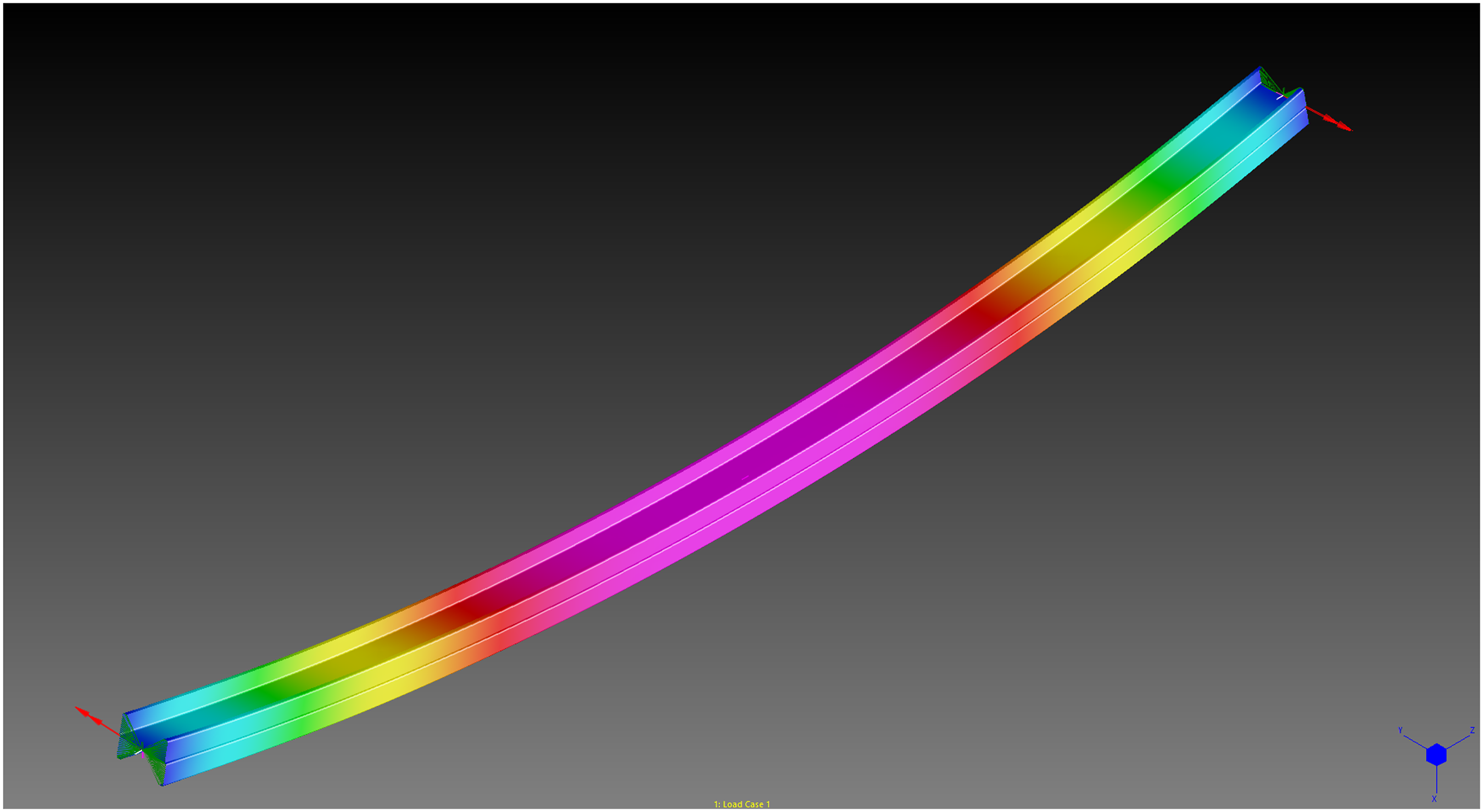
As expected, the effective second moment of area I y,eff falls between the value for two single channels and the value for full composite action (FCA). Figure 17 shows that I y,eff depends on the spacing of the screw fasteners and gradually increases as the spacing between the screw fasteners is reduced. Even when only one pair of screw fasteners is used at mid-span (s/L = 0.5) the value of I y,eff is 1.25-1.29 times greater than the value for two single channels.
Also shown in Figure 17 is the normalised second moment of area assuming full composite action (FCA). As expected, the second moment of area assuming full composite action is higher than the second moment of area for screw fastened channels, and is 1.60-1.66 times the value for two single channels.
The results shown on the graph in Figure 17 can be compared with the minor axis bending test results obtained by Phan and Rasmussen (2019) for 1.0 mm and 3.0 mm thick back-to-back channel sections. Their values for I y,eff /2I y for channels with 4 and 8 rows of screw fasteners fall in the range 1.23-1.53 which is similar to the range shown in Figure 17.
Uniform torsion
Using the values of d
b
in Table 5 for each channel thickness, a linear static analysis in Strand7 was performed for each 5 metre long back-to-back channel under uniform torsion. Using the maximum twist rotation obtained from the finite element analysis, the effective torsion constant J
eff
was calculated from equation (3). Figure 19 shows the variation of J
eff
normalised with double the torsion constant for a single channel 2J with the screw fastener spacing ratio s/L. Figure 20 displays a typical deformed shape for back-to-back channels under uniform torsion. Variation of torsion constant with screw fastener spacing. Typical deformed shape for uniform torsion (C20015 with s/L = 0.2).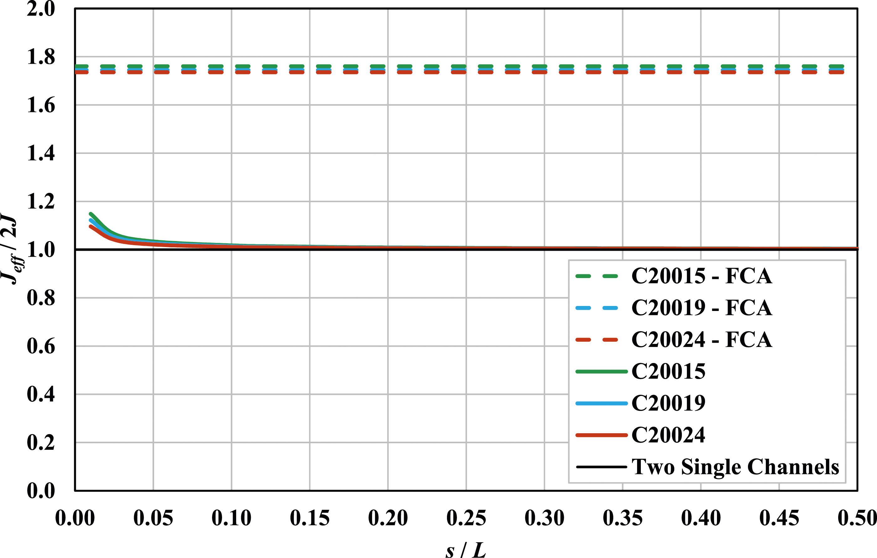

It can be seen in Figure 19 that the effective torsion constant is equal to the torsion constant for two single channels, indicating that the screw fasteners have no effect on the torsion constant until the spacing of the screw fasteners becomes very small. This result confirms the findings by Rasmussen et al. (2020) who showed that the screw fasteners in open sections under uniform torsion do not experience shear deformation and hence the effective torsion constant of an open built-up section is equal to sum of the torsion constants of the individual sections. As mentioned previously, the torsional rigidity is very much smaller than the warping rigidity for cold-formed steel channels and so doubling the torsion constant will only have a small effect on the elastic flexural-torsional buckling moment for back-to-back channels.
Also shown in Figure 19 is the normalised torsion constant assuming full composite action (FCA). As expected, the torsion constant assuming full composite action is higher than the torsion constant for screw fastened channels, and is approximately 1.75 times the value for two single channels.
Non-uniform torsion
Using the values of d
b
in Table 5 for each channel thickness, a linear static analysis in Strand7 was performed for each 5 metre long back-to-back channel under non-uniform torsion. Using the maximum rotation obtained from the finite element analysis, the effective warping constant I
w,eff
was calculated from equation (4). Figure 21 shows the variation of I
w,eff
normalised with double the warping constant for a single channel 2I
w
with the screw fastener spacing ratio s/L. Figure 22 displays a typical deformed shape for back-to-back channels under non-uniform torsion. Variation of warping constant with screw fastener spacing. Typical deformed shape for non-uniform torsion (C20015 with s/L = 0.2).

It can be seen in Figure 21 that the effective warping constant is more than double the warping constant for two single channels and is very close to the warping constant assuming full composite action (FCA). The reason for this is that there are no warping displacements in the web of the back-to-back section, as shown in Figure 23 taken from THIN-WALL-2. Therefore, the value of the warping constant is independent of the connection between the two webs, whether it be screw fasteners or full composite action. However, the reason why the effective warping constant is slightly lower than the full composite value is because there is still a slight gap between the web centrelines which is causing some minor warping displacements in the two webs and subsequent shear deformation in the screw fasteners. Warping displacements in back-to-back channel.
Design proposal
Cold-formed steel members have traditionally been designed by the effective width method (Hancock, 2022). However, the presence of screw fasteners at intermediate intervals in back-to-back channels precludes a simple derivation of effective width design equations for these types of members. On the other hand, the direct strength method (Schafer, 2019) provides a more rational basis for designing cold-formed steel members by using elastic buckling stresses and strength curves to obtain the design capacity without the need to perform complicated effective width calculations. The following design proposal applies the existing direct strength design equations to back-to-back channels but uses the section properties for single channels which are straightforward to calculate. Although only flexural-torsional buckling was investigated in this study, design proposals for local and distortional buckling of back-to-back channels are also presented below.
For cold-formed steel members subjected to bending moment, the design moment capacity M
be
for flexural-torsional buckling in the absence of local buckling is currently given in AS/NZS 4600 (Standards Australia/Standards New Zealand, 2018) and AISI S100-16 (American Iron and Steel Institute, 2016) as follows


For cold-formed steel members in bending where flexural-torsional buckling interacts with local buckling, the design moment capacity for local buckling M
bl
is currently calculated as follows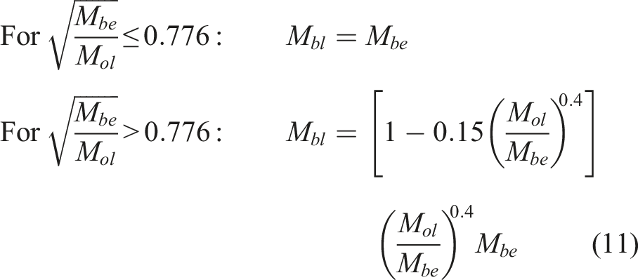

For cold-formed steel members which undergo distortional buckling, the design moment capacity for distortional buckling M
bd
is currently calculated as follows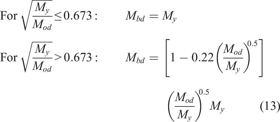

To confirm the above design proposal and possible acceptance in design standards, future work which involves bending tests and non-linear analysis on back-to-back cold-formed steel channels would need to be performed. Beams with different lengths can be studied so that local, distortional and flexural-torsional buckling can all be investigated. The ultimate moments obtained from these tests and analysis can then be compared with the above design proposal. A reliability analysis as described in Chapter K of AISI S100-16 would also need to be performed to assess the reliability of the design proposal.
Conclusions
The elastic flexural-torsional buckling moment for a beam is used in many design standards as the basis for the determination of the flexural-torsional buckling moment capacity. Although the calculation of the elastic flexural-torsional buckling moment is a simple procedure for single sections where the section properties can be easily calculated, this calculation for back-to-back channels with intermediately spaced screw fasteners is more complicated because the screw fasteners cause a discontinuity of the cross-section along the length of the beam.
In this paper, a finite element analysis is described to calculate the bending, torsion and flexural-torsional buckling moment for back-to-back cold-formed steel channels with intermediately spaced screw fasteners. The screw fasteners were modelled as short solid cylindrical beam elements positioned between adjacent nodes on the two webs. The shear stiffness of the screw fasteners was obtained from test results and used to calculate an appropriate diameter for the beam elements. The finite element model was validated by comparing the elastic flexural-torsional buckling moment and section properties with the theoretical values assuming full composite action.
The results show that the elastic flexural-torsional buckling moment M eff for back-to-back channels is significantly higher than the elastic flexural-torsional buckling moment for two single channels but less than the elastic flexural-torsional buckling moment assuming full composite action. The results also show that only a few screw fasteners are required to gain a significant increase in the elastic flexural-torsional buckling moment. For example, by only having one row of screw fasteners at mid-span (s/L = 0.5) the elastic flexural-torsional buckling moment is increased over the value for two single channels by a factor of 1.45. A much larger increase by a factor of 1.64 can be obtained when the screw fasteners are spaced closer together (s/L = 0.1).
A linear bending finite element analysis was performed to calculate the effective minor axis second moment of area I y,eff for back-to-back channels. Because the screw fasteners in back-to-back channels subjected to minor axis bending undergo shear deformations, the shear stiffness and spacing of the screw fasteners will have a significant effect on the minor axis bending behaviour of the channels. The results show that the value of I y,eff for back-to-back channels is higher than the value for two single channels by a factor which ranges from 1.25 for one row of screw fasteners at mid-span (s/L = 0.5) to 1.45 for more closely spaced screw fasteners (s/L = 0.1).
A uniform torsion finite element analysis was performed to calculate the effective torsion constant J eff for back-to-back channels. The results show that the value of J eff for back-to-back channels is the same as the value for two single channels. This is because the screw fasteners do not experience shear deformation in open sections under uniform torsion. In any case, doubling the torsion constant for back-to-back channels will only have a small effect on the elastic flexural-torsional moment because the torsional rigidity is very much smaller than the warping rigidity for cold-formed steel channels.
A non-uniform torsion finite element analysis was performed to calculate the effective warping constant I w,eff for back-to-back channels. The results show that the value of I w,eff for back-to-back channels is twice the value for two single channels and very close to the value for full composite action. This is because there are no warping displacements in the web of back-to-back channels and therefore, the value of the warping constant is independent of the connection between the two webs, whether it be screw fasteners or full composite action. Thus, back-to-back configurations do not affect the uniform torsion resistance but they do increase the non-uniform torsion resistance.
A design proposal is presented for the flexural-torsional buckling moment capacity of back-to-back channels by the direct strength method. The moment capacity depends on the elastic flexural-torsional buckling moment which is calculated by factoring the section properties I y , J and I w for a single channel by 2.5, 2.0 and 4.0, respectively.
The key parameter to consider in the design of back-to-back channels is the spacing of the screw fasteners. Installing screw fasteners involves additional cost which must be considered by the structural designer, who has to weigh up the cost versus benefit. There is a large increase in the elastic flexural-torsional buckling moment even when just one pair of screw fasteners is used (ie s/L = 0.5). Adding extra screw fasteners only increases the elastic flexural-torsional buckling moment slightly and it is not until s/L becomes very small that a very significant increase in the flexural-torsional buckling moment is obtained. This means many screw fasteners have to be installed to get a significant benefit over the initial increase. The structural designer has to decide if the extra cost is worth it.
Future work would involve bending tests and non-linear analysis on back-to-back cold-formed steel channels to obtain the ultimate moments and compare with the design proposal. Beams with different lengths can be studied so that local, distortional and flexural-torsional buckling can all be investigated. A reliability analysis would also need to be performed to assess the reliability of the design proposal.
Footnotes
Declaration of conflicting interests
The author(s) declared no potential conflicts of interest with respect to the research, authorship, and/or publication of this article.
Funding
The author(s) received no financial support for the research, authorship, and/or publication of this article.
