
Abstract
This study presents an innovative H-shaped aluminum-timber composite (ATC) beam with beveled flange platform, designed to enhance the positioning and assembly of inclined self-tapping screws. Through push-out tests on dual shear interfaces across 13 groups, we evaluated the load-displacement behaviors and failure mechanisms under various screw layouts. Our findings indicate that longer screws increase shear capacity at a slight stiffness reduction. The decline in shear performance for screws with cylindrical sections is attributed to size shrinkage at the shear plane, although this shape enhances stiffness during initial deformation due to tight contact with H-aluminum drilling holes. A group effect analysis shows that triple rows of screws reduce shear capacity by 25.2% versus a single row, highlighting the impact of screw arrangement on structural integrity. Comparisons with Eurocode 5 theoretical calculations confirm the reliability of our results, highlighting the potential of inclined screws in ATC joints.
Keywords
Introduction
Inspired by the concept of steel-concrete composite beams and slabs used in multi-story and high-rise buildings (Ahmed and Tsavdaridis, 2019), the combination of H-shaped aluminum profiles with timbers on each side of the flange meets the prerequisites of lightweight, high-strength, low-cost materials, and construction convenience. This approach offers two main benefits: Aluminum alloys have become popular structural materials due to their high strength-to-weight ratio, ease of extrusion, and high corrosion resistance (Georgantzia et al., 2021). Timber, compared to traditional concrete, significantly reduces energy consumption and carbon emissions, contributing to a sustainable, natural living and working environment (Chiniforush et al., 2018). Timber products like glued laminated timber (GLT) (Shi et al., 2022; Zhao et al., 2022), cross-laminated timber (CLT) (Loss and Davison, 2017; Loss et al., 2016), and laminated veneer lumber (LVL) (Chiniforush et al., 2019; Chybiński and Polus, 2021) also offer excellent load-bearing capacity and ease of assembly (Ringhofer et al., 2018).
When it comes to composite beams, connectors that assemble different materials are crucial, as they bear the shear force between interfaces under the plane section assumption (Wu et al., 2005). In these structures, the upper timber beam resists compression, the metal girder undertakes tension, and shear is transferred through connectors (Chybiński and Polus, 2019). Based on relative slip and stiffness, connectors can be rigid or flexible (Zhou et al., 2022). Rigid connectors like epoxy resin adhesives (Schäfers and Seim, 2011) provide strong bonds but face issues with residual stresses and deflections due to temperature and humidity changes (Eisenhut et al., 2016). Flexible connectors, including dowels, bolts, nails, screws, and staples, allow for bending deformation (Jockwer et al., 2018). Shear performance of the interface is critical for composite beams. Research on inclined screw connections has demonstrated that inclination can effectively improve connection stability and performance (Aloisio et al., 2024a; De Santis et al., 2023).
To address bending moment capacity and timber failure, increasing the size and strength grade of connectors and timber can help. However, insufficient embedding strength, limited by the thin timber beams, and improper angulation of dowel-type fasteners complicate on-site installation. The thinness of timber beams and the equilateral flanges and small height of the web plate hinder the proper use of screw guns. Without changing standard manufacturing processes to thicken timber beams, potential solutions lie in modifying H-shaped aluminum profiles and connector angulation. Wang et al. (2020) proposed using inclined screws with tapered washers to simulate screws perpendicular to the flange in projection length and contact interface angle. While this improved embedded depth and operation convenience, locating and fixing tapered washers was time-consuming and difficult for a single worker. Aleatoric and epistemic uncertainties in the overstrength of CLT-to-CLT screwed connections have also been studied, highlighting factors impacting connection reliability in composite structures (Aloisio et al., 2024b). The interaction between tapered washers and various H-shaped metal profiles also remains to be explored.
Considering the maneuverability of accurate positioning tapper washers and quick assembling self-tapping screws with H-aluminum profiles, this paper innovatively proposed a H-shaped aluminum profile with a special-shaped cross section, integrating tapper washers into the inner edges of the flange, which can be easily formed into one piece by means of extrusion and drawing. The bevel platform had a positioning groove in the middle to ensure accurate drilling of the screws. The overall assembly diagram is vividly shown in Figure 1(a) and (b) depicts the lateral view (with specific dimensions) of the H-shaped aluminum-timber composite beam. H-shaped aluminum-timber composite beam.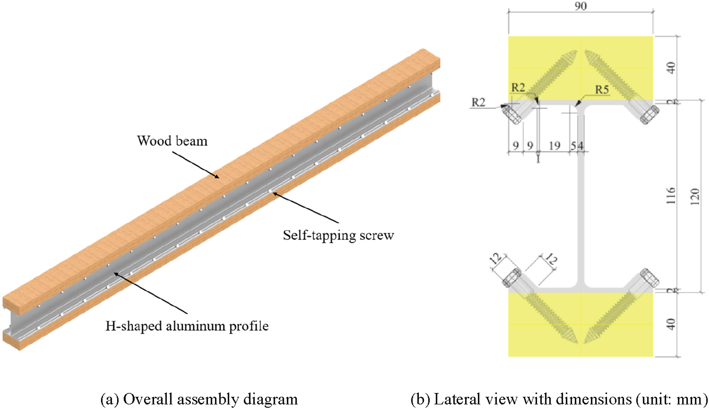
In this paper, a series of 13 push-out experiments is conducted for aluminum-timber composite beams with inclined self-tapping screws. The effects of different diameters, thread types and failure status of the self-tapping screws are evaluated. Group influences on the shear capacity including a single row and triple rows of both inclined and perpendicular screws are compared. The outcomes of this experiment will lay a foundation for future research on the four-point bending test of these innovative aluminum-timber composite beams.
Experimental details
Specimen design
Figure 2 illustrates the configurations and specific dimensions of specimens in the push-out test. The colored translucent views of four types of specimens are explicitly demonstrated in Figure 2(a) for a better understanding of specific layout. The specimens consist of H-aluminum and northeastern pine timber rectangular beam combined by vertical and inclined self-tapping screws. Dimension of specimens for push-out tests (unit: mm).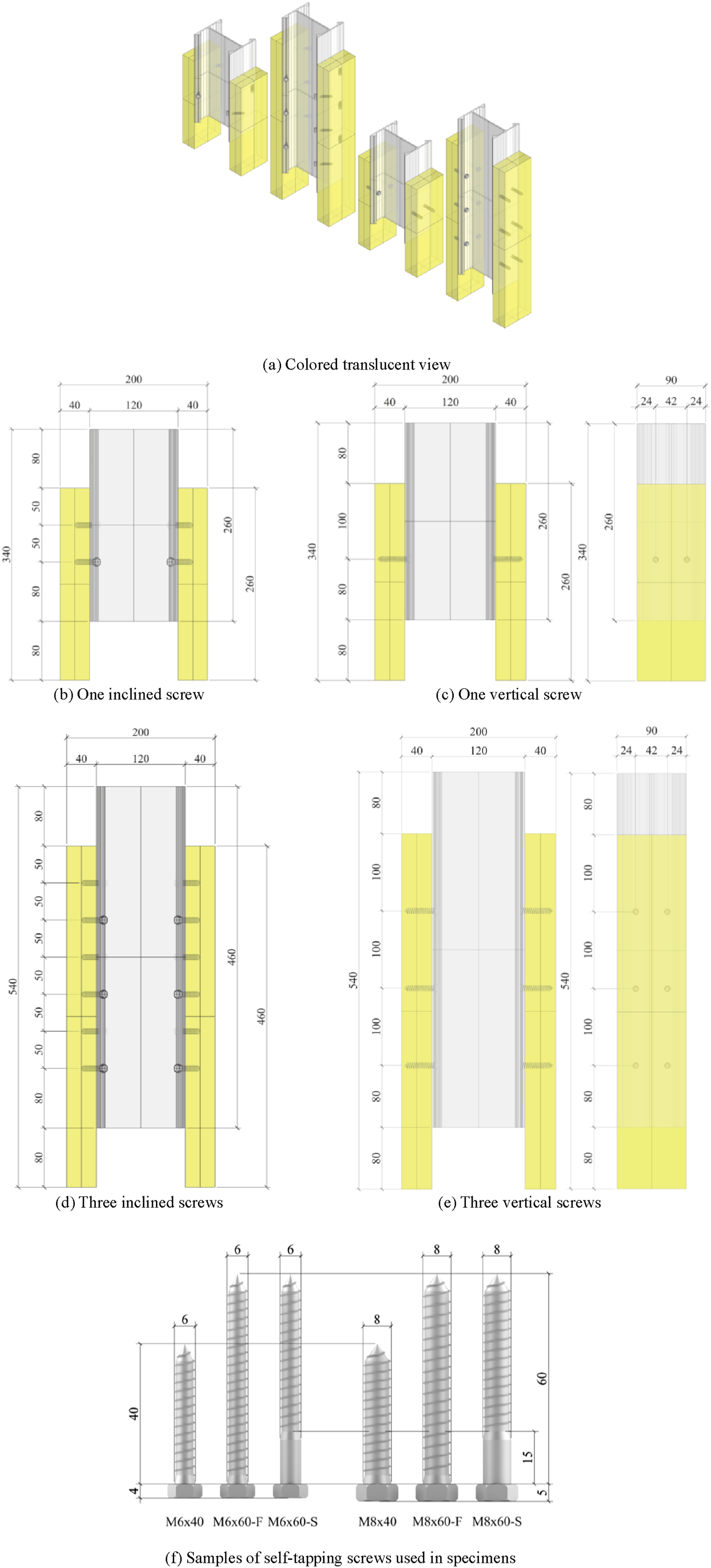
The dimension of H-aluminum profile is 90 × 120 × 4 × 2 mm. In accordance to fit the width of H-aluminum flanges, the timber, with a 40 × 90 mm rectangular cross-section, are made from high-quality and uniform-grained logs after carefully screening. Multi-blade sawing is one of the most significant manufacturing procedures to ensure that the timber beams are of standard size with smooth and flat sides. After the fabrication, the timber beam is vertically cut into cuboids with lengths of 260 mm and 460 mm. Each shear plane of the specimen features two columns of screws: Figure 2(b) and (d) have one screw per column, while Figure 2(c) and (e) have three screws per column. The connections are available in two types, which are semi-threaded and fully-threaded hexagonal self-tapping screws respectively, conforming to DIN 571:2016 (2016) and satisfying EN 14592:2008 (2008) requirements for dowel-type fasteners.
Parametric details of all specimen groups.
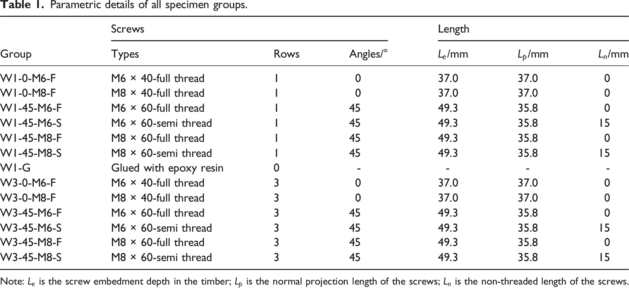
Note:
The group name of Wx-α-My-Z are consisted of the following parts. W means the abbreviation of the word widget. x represents the quantity of rows of screws per column. α symbolizes the angulation between the normal line of the interface of timber beam and the axis of the screw. M is just the abbreviation of the word model. y represents the diameter of the screws. Z stands for the screw types in either full thread or semi thread with an abbreviation of F or S.
The design of the parametric details of above specimens is undergone due consideration:
First, in specimen groups W1-0 and W1-45, the angulation α of the self-tapping screws are 0 and 45° with a length of 40 and 60 mm and a diameter of 6 and 8 mm, which are comparatively depicted in Figure 2(b) and (d). Their projection lengths
Second, we had found that self-tapping screws with a cylindrical section are more favored among framework constructors. Thus, we replaced two types of self-tapping screws (M6 × 60 & M8 × 60) with a 15 mm-long cylindrical section, as is explicitly illustrated in Figure 2(f). These self-tapping screws remain the same in all other aspects including lengths, diameters, strength grades and material properties.
Finally, the group effects of specimens with triple rows of self-tapping screws were investigated and compared with those with a single row.
As illustrated in Figure 2(b)–(e), an allocation of 80 mm-distance was left at the top and bottom part of the specimen for the loading procedure. The thin iron plate was fixed at the upper end of the H-aluminum to secure the even load distribution.
The allocation of screws complied with Eurocode 5 (2004) and GB 50017–2017 (2017). As demonstrated in Figure 2(c) and (e), the longitudinal interval between self-tapping screws with multiple rows on the same side of the flange is 100 mm.
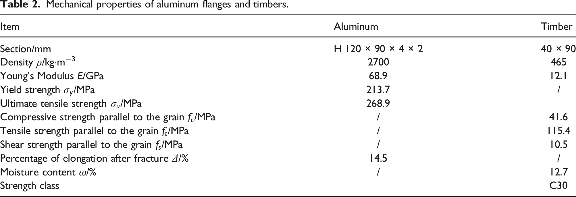
Material properties
Mechanical properties of aluminum flanges and timbers.
Experimental equipment
Figure 3 shows the on-site practice and schematic diagram of the equipment layout for the push-out tests. All tests were conducted using a SANS electronic hydraulic test machine. The timbers were supported by a base steel plate, and the load from the test machine was applied to another steel plate fixed on top of the H-aluminum. Two displacement transducers measured the relative displacement between the H-aluminum and the timbers. The L-steel sheets were adhered to the flange with epoxy resin. Equipment layout for push-out tests.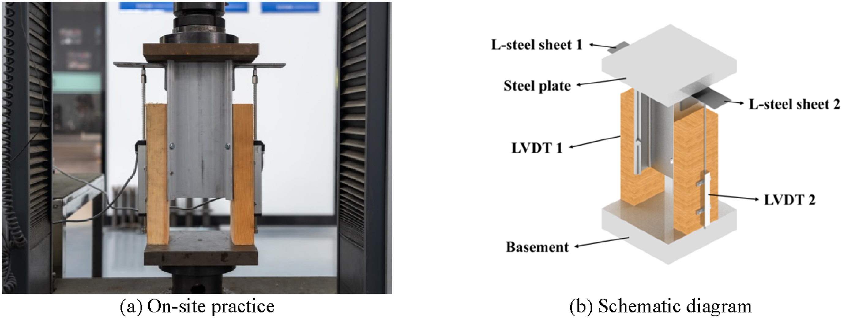
Loading scheme
Figure 4 illustrates the loading scheme for the push-out tests, which follows EN 26891:1991 (1991) concerning the static load procedures of mechanical joints in timber structures. Loading scheme of push-out tests.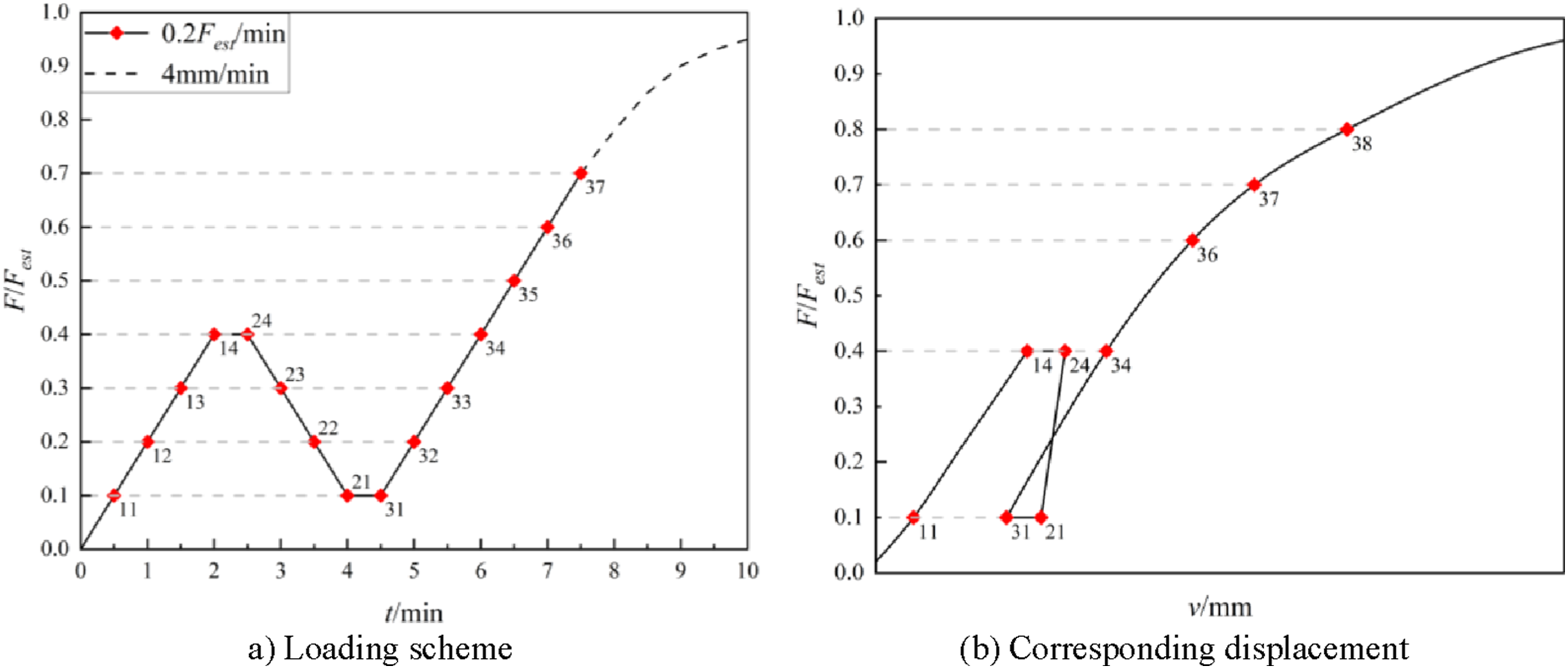
Experimental phenomena
Load-displacement response
Figure 5 depicts the load-displacement responses. The X-axis symbolizes the relative displacement of the aluminum-to-wood interface, while the Y-axis means the value of corresponding load. To address the potential separation of occasional and systematic errors, each group includes two additional alternatives. For the purpose of explicit differentiation, we have labeled the curves with suffixes (a), (b) and (c) and light blue, purple and green dash lines are deployed. The red solid line emphasizes mean fitting results of the above three curves. Load-displacement curves.
Concluded from Figure 5(a)–(j), sudden drops of loading capacity frequently occurred, mainly attributing to the shear failure of the self-tapping screws. Three specimens in group W1-0-M6-F (Figure 5(a)) all had several sudden drops, revealing that the shear loss appeared in sequence with the increase in the displacement of the specimen. However, these sudden decreases in the ordinates came at a large random, demonstrating that even in the same group, large dispersion was still inevitable. Under such circumstances, the average curves of specimens only ranged from zero to the abscissa of displacement where one of the screws first broke.
Apart from the above specimens in Figure 5(a)–(j), the rest did not exhibit obvious shear loss when the displacement is smaller than 30 mm. As the displacement gradually accumulates, the bearing performance of the specimen with a single row of screws in group W1-45-M8-S and multiple rows of screws in group W3-45-M8-S did not decline significantly and presented excellent ductility.
Failure states
As manifested in Figure 6, the failure states are categorized into three genres. For State A, it is observed that a plastic hinge is formed close to the interface. For State B, two plastic hinges are formed, one in the middle and the other close to the interface. For State C, the timber was also crushed and the screw was cut off from one of the possible plastic hinges. Failure modes of self-tapping screws.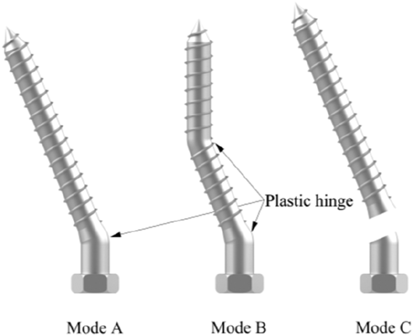
Failure states of specimen groups.


Failure modes of specimens with single row of screws.

Failure modes of typical specimens with three rows of screws.
Taking a close look at State C, the broken interface of the semi-threaded screw occurred on the intersection between the non-threaded and threaded part, because there is section shrinkage at this position, resulting in a high likelihood of stress concentration.
As depicted in Figure 8, for specimens with triple rows of screws, the phenomenon of wood splitting damage accompanied with irregular triangular prism slippage was observed. This combination destruction will be further analyzed in next section.
Discussion on test results
Overall mechanical properties of connections
The specifications involving EN 26891:1991 Timber structures - Joints made with mechanical fasteners – General principle for the determination of strength and deformation characteristics (BS EN 26891:1991, 1991) and EN 12512:2001 Timber structures – Cyclic testing of joints made with mechanical fasteners (BS EN 12512:2001, 2001) are taken into consideration, and the load-displacement parametric details are concluded in Appendix A. As shown in Figure 9, the initial stiffness (1) (2) Yield point (3) (4) D is the ratio of the ultimate displacement to the yield displacement, Definitions of stiffness and shear capacity.


Average values of the mechanical parameters of all specimen groups.

Note: The percentages are the CoV.
* just means another group with same dimension and conformation, including three specimens.
Performance of inclined self-tapping screws
Figure 10 compares the load-displacement curves of the joints between perpendicular and inclined self-tapping screws in groups W1-0-M6-F, W1-45-M6-F, W1-0-M8-F and W1-45-M8-F, demonstrating that group W1-45-M8-F (purple line) possesses satisfying elastoplastic behavior and relatively good ductility, while the other three groups all encounter sudden shear failure without declining stage. Load-displacement curves of joints between perpendicular and inclined self-tapping screws.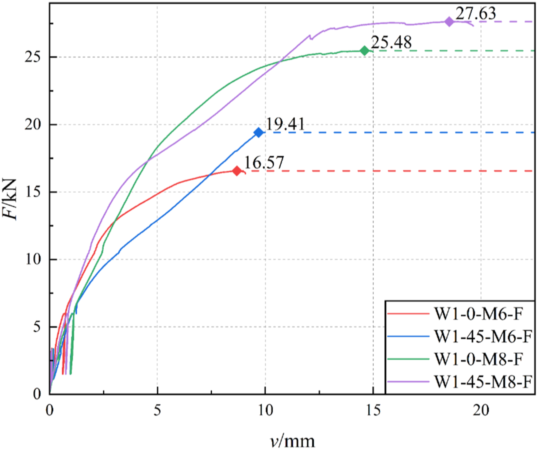
When it comes to loading parameters in Table 4, these groups exhibit different characteristics. The
Nevertheless,
The variation of yield load
When the load is below 5 kN, there is no apparent movement at the aluminum-timber interface. This can be attributed to the pre-tightening force originating from screw threads, and the close fit between the self-tapping screw head and the bevel platform of the H-aluminum flange. Comparing
Although the value of
In conclusion, the longer self-tapping screws can be used in the ATC joint with bevel platforms on the flange to increase the embedded depth in the timber. In this way, a higher shear capacity can be obtained at a sacrifice of a slight decline in stiffness. Taking diameters into consideration, M6 is more efficient in improving the load-bearing capacity and prolonging the yield stage than M8 in the practice of this kind of H-shape aluminum profiles with bevel platforms.
Effect of the semi-threaded screws
Figure 11 compares the load-displacement curves of the joints between full- and semi-threaded self-tapping screws in groups W1-45-M6-F, W1-45-M6-S, W1-45-M8-F and W1-45-M8-S, demonstrating that group W1-45-M8-F (green line) and W1-45-M8-S (purple line) have features similar to elastoplastic behavior, while the other two suffer sudden shear failure without decreasing stage. Load-displacement curves of joints between full- and semi-threaded self-tapping screws.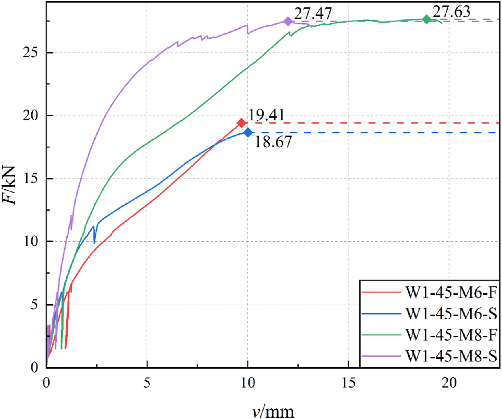
Comparing loading parameters in Table 4, the
However, in the contrast between W1-45-M6-F and W1-45-M6-S,
Group effect of self-tapping screws
In Figure 12, the load-displacement responses of perpendicular self-tapping screws are compared, specifically between those with one row per column and those with triple rows per column. The Comparison of perpendicular self-tapping screws with different rows per column.
The group effect of self-tapping screws significantly impacts the stiffness and shear capacity of the joint, leading to a decline in mechanical performance. This is due to uneven load distribution from nonidentical screw slips under maximum load. Screws with higher loads are more prone to sudden shear failure, reducing overall shear capacity.
In Figure 13, load-displacement curves of inclined screws with different rows per column are compared. The group effects are minimal in Figure 13(a) and (b) as the lines nearly overlap. This uniform distribution of inclined screws maintains similar shear capacity compared to more compact perpendicular screws. Comparison of inclined self-tapping screws with different rows per column.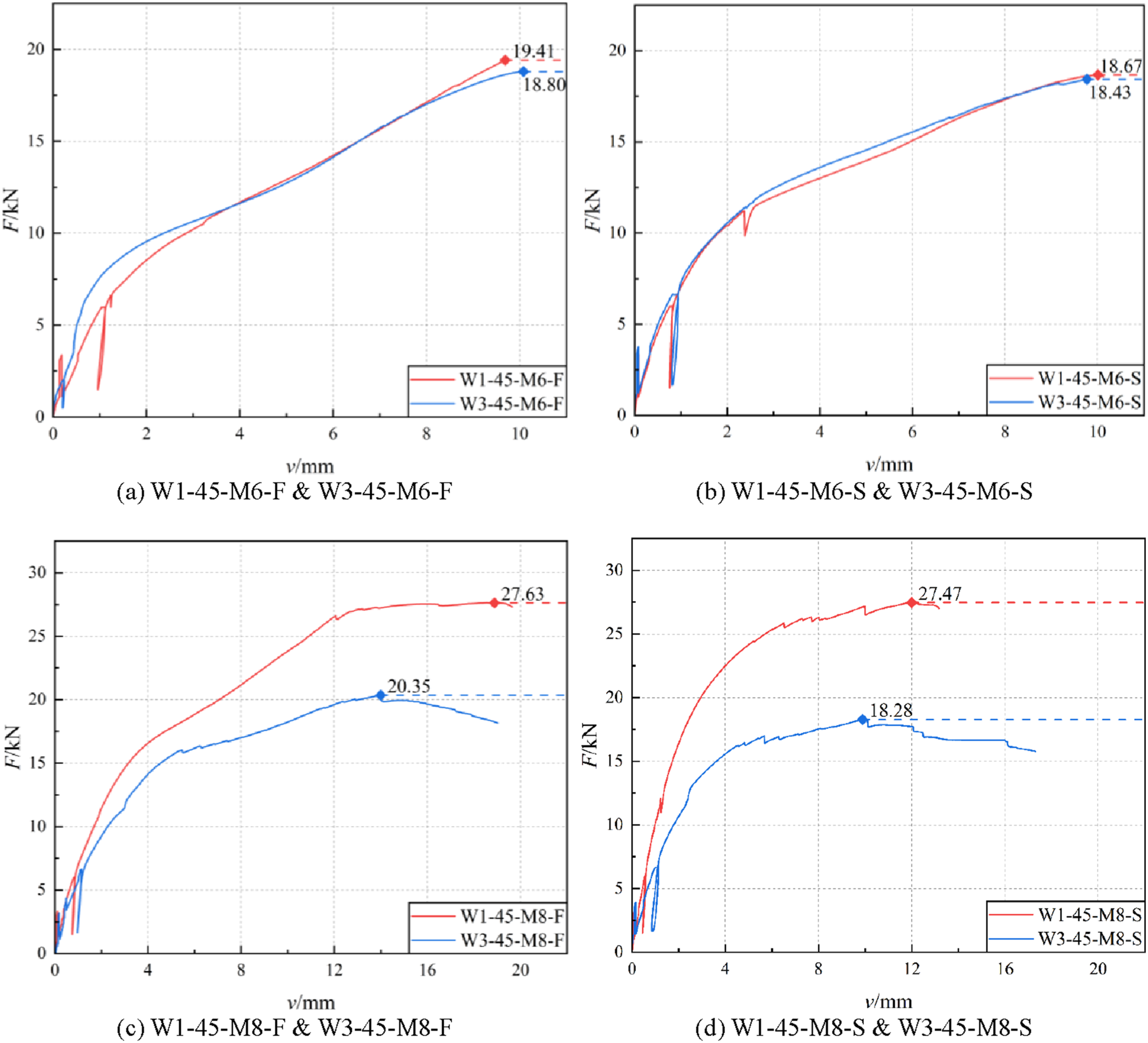
In Figure 13(a) and (b), all curves are smooth and terminate suddenly due to shear failure of the screws. In contrast, Figure 13(c) and (d) show jagged fluctuations during the yield stage, aligning with the failure modes in Figure 8. As mentioned in Section 3.2, this failure state, including wood splitting and State A screw failure, can be simplified into a triangular prism, as depicted in Figure 14. Interpretation of triangular prism.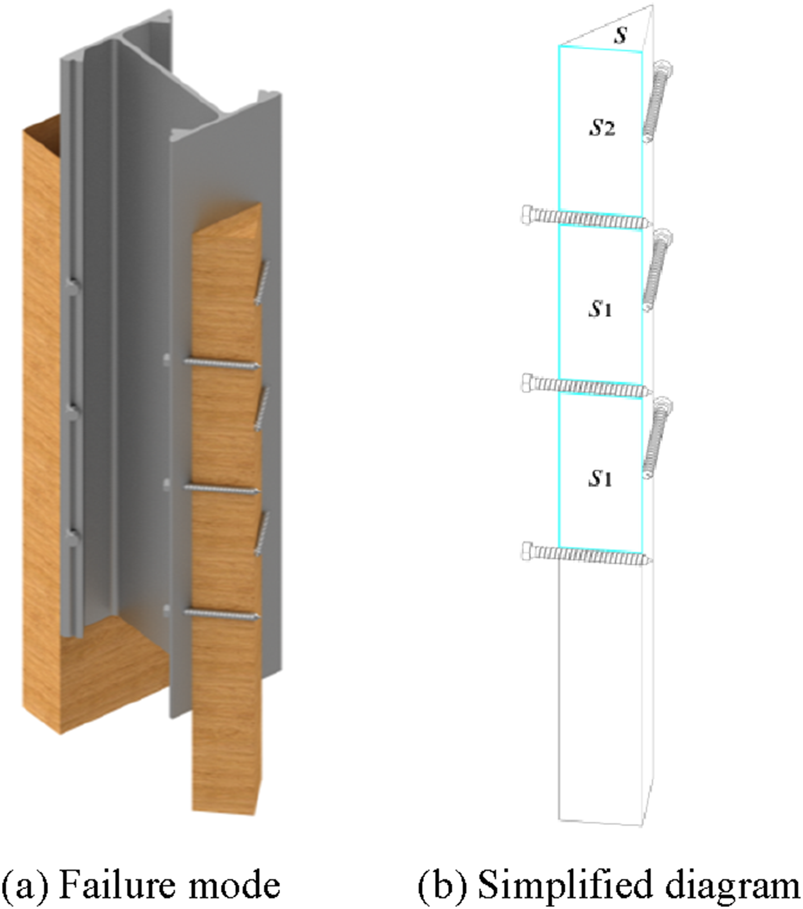
This failure likely occurs due to the close lateral interval between screws, creating a weak cross-sectional area unable to sustain tensile damage. Additionally, larger diameter self-tapping screws may leave tiny tensile fractures during drilling.
Comparison between experimental and theoretical results
Aluminum’s mechanical properties are similar to steel’s (Liu et al., 2020), making the Eurocode 5 formula for steel-to-timber connections applicable to aluminum-timber connections.
Shear capacity design for steel-to-timber connections is divided into five main categories by the thickness of the steel plate and the number of shear planes: (1) A thin steel plate in single shear (thickness less than or equal to half of the connector diameter), (2) A thick steel plate in single shear (thickness greater than or equal to the connector diameter), (3) A steel plate of any thickness as the central member of a double shear connection, (4) Thin steel plates as the outer members of a double shear connection, (5) Thick steel plates as the outer members of a double shear connection (BS EN 1995-1-1:2004, 2004).
In this test, the H-shaped aluminum profile is centered between two timber beams, which belong to the third type. Thus, the formula of shear bearing capacity of self-tapping screws is expressed as follows:
M
y,Rk
, 


Particularly, the yield moment 
As for the group effect of self-tapping screws, code provides the strength reduction coefficient 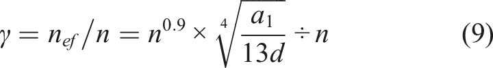
Comparison between theoretical and experimental results.

The values in the brackets represent the deviation in percentage between theoretical and test results, which can be explicitly demonstrated in Figure 15. From Figure 15(a), all errors between theoretical shear capacity and maximum load within the slip of 7.5 mm are within the scope of 20%, thus the equation (4) can be regarded as a fairly good evaluation. In Figure 15(b), the theoretical results, as calculated according to Eurocode 5, consistently show lower shear capacity compared to the corresponding experimental values, which provides a conservative estimate for the design of these connections, ensuring an added margin of safety. Correlation plot between theoretical and test shear capacity.
Conclusions
This paper proposes an innovative H-shaped ATC beam with a bevel platform on the flange, aiming to simplify assembly and enhance shear performance by allowing the use of longer self-tapping screws. A series of push-out tests was conducted on 13 groups of ATC joint specimens with dual shear interfaces, with analysis on load-displacement responses, stiffness, shear performance, ductility, and failure modes. The primary findings are summarized below: (1) The traditional ATC joint, which uses vertically oriented self-tapping screws, presents challenges in installation due to the normal interface orientation, limiting the embedment depth of screws because of the limited timber thickness. This configuration impacts the joint’s overall performance. With similar projection lengths, longer embedded screws enhance the shear-bearing capacity. The use of extended screws in ATC joints with pre-drilled holes on the bevel platform increases timber embedment depth, resulting in higher shear capacity with only a slight reduction in stiffness. (2) The reduced shear performance of semi-threaded screws is primarily attributed to size shrinkage at the shear plane, leading to concentrated stress points that can form plastic hinges or cause shear failure. However, the cylindrical section of the screws maintains greater stiffness during initial deformation due to tight contact with the pre-drilled holes in the H-shaped aluminum profiles. (3) Multiple rows of self-tapping screws significantly affect stiffness and shear capacity, reducing joint performance. Uneven load distribution caused by varied slip per screw under maximum load leads to higher loads on certain screws, making them more susceptible to sudden shear failure. Shear capacity declines by an average of 25.2% compared to single-row screws, as evidenced by the triangular prism failure analysis. (4) The minimal deformation of the aluminum profile during tests indicates its limited direct impact on the push-out performance. However, the aluminum component offers notable benefits in practical applications, such as reducing overall weight, simplifying on-site assembly, and allowing for convenient connections with self-tapping screws without compromising connection quality. Additionally, the beveled platform functions as a stiffening rib, enhancing the flange stiffness of the aluminum beam. (5) Comparison of experimental results with Eurocode 5 theoretical calculations confirms the reliability of the tests, demonstrated by the small error percentages in shear capacity and strength reduction coefficient.
The purpose of this article is to demonstrate the feasibility of the H-shaped aluminum-timber composite beam with a beveled flange platform and to acquire data on the mechanical properties of the screws for the subsequent four-point bending test and corresponding finite element analysis. If needed, further experiments focused on comparing aluminum with other metal profiles will be conducted in the future to broaden the understanding of material choices and their impacts on joint performance.
Footnotes
Declaration of conflicting interests
The author(s) declared no potential conflicts of interest with respect to the research, authorship, and/or publication of this article.
Funding
The author(s) disclosed receipt of the following financial support for the research, authorship, and/or publication of this article: The work presented in this article was supported by the National Natural Science Foundation of China (Grant No. 51308105), the Fundamental Research Funds for the Central Universities (No. 2242022k30030).