




Abstract
Columns are critical to structural integrity, as elevated temperatures can weaken them and cause collapse, necessitating detailed studies on their behavior under such conditions. This study investigates the axial capacity of eleven heat-damaged reinforced concrete (RC) columns through experimental and numerical methods. Columns (200 × 200 × 1200 mm) were subjected to temperatures of 400°C and 600°C for 90, 120, and 150 minutes, followed by natural cooling. Strengthening was applied using RC jacketing, steel jacketing, and CFRP wrapping sheets. Variables included temperature, exposure duration, different strengthening techniques, concrete compressive strength, and concrete cover size. The compressive strength reduction reached a maximum of 44% after 150 minutes of fire exposure. Strengthening techniques and increasing concrete cover improved the overall behavior and ultimate load capacity. Numerical analysis using ABAQUS closely matched experimental results, confirming its accuracy in predicting column behavior under elevated temperature-damaged conditions. The findings can assist the structural engineer in determining the most effective strengthening technique for such columns and enhancing their performance after exposure to elevated temperatures.
Keywords
Introduction
Concrete is one of the most used materials in the construction field, with a consumption rate of 10 billion tons annually and an expected increase by 2050 (Adamu et al., 2024). Although concrete has high fire resistance, its mechanical properties decline significantly at elevated temperatures due to crack formation, chemical changes, and increased pore pressure from evaporated water. The increasing frequency and severity of fires, exacerbated by climate change, have led to significant loss of life and property damage (Kodur et al., 2024). This has drawn researchers’ attention to the urgent need to understand the behavior of reinforced concrete structures under high temperatures (Abadel, 2024; Cao and Trinh, 2023; Mohamad et al., 2020; Shin et al., 2024; Zghair et al., 2022). On the other hand, RC columns play a pivotal role in skeleton structures; their failure may cause the building to collapse in part or in its whole (El-Shafiey et al., 2025). RC columns are more critically affected by elevated temperatures than other structural elements. This is attributed to the fact that high temperatures weaken both concrete and steel reinforcement, significantly reducing compressive strength and stiffness. Moreover, thermal gradients cause spalling and internal stress, hastening deterioration and undermining the axial capability. All of this highlights the urgent need to determine the most suitable technique to strengthen these columns after exposure to elevated temperature.
Structures may not undergo complete failure during a fire. Consequently, safely repairing the structure and restoring its functionality might be more practical and economical than destruction and complete or partial reconstruction (Ekmekyapar and Alhatmey, 2019). Several past studies have concentrated on strengthening RC columns against excessive loads using different methods (Deng et al., 2018; Liu et al., 2017; Ou and Truong, 2018). Traditional approaches include RC or steel angle jacketing, while modern methods involve various types of fiber-reinforced polymer wrapping sheets. All these techniques enhance the performance of RC columns by improving their ultimate load capacity. The reinforced concrete jacketing technique is an efficient and cost-effective solution that significantly enhances the load-carrying capacity, durability, and stiffness, and provides protection against both corrosion and fire (Campione et al., 2014). Proper surface treatment is essential to ensure a strong bond between the original column surface and the RC jacket.
Aldhafairi et al. (2020) investigates various steel jacketing techniques for retrofitting concrete beams exposed to elevated temperatures, demonstrating their effectiveness in restoring structural integrity and load capacity. Belal et al. (2015) reported that the use of steel jackets for column strengthening resulted in a strength increase of at least 20%. A Study by Tarabia and Albakry (2014) observed even higher strength gains, reaching up to 66% and 90%, respectively. The steel jackets not only enhanced the stiffness and ductility of the columns but also fulfilled the requirements necessary for a reliable seismic response (Khalifa and Al-Tersawy, 2014; Raza et al., 2019). It is important to acknowledge that the frictional interaction between steel angles and mortar should not be disregarded (Campione et al., 2014). Abdel-Hay and Fawzy (2015) have focused on the impact of placing steel jackets on the outer surface of the column. However, a more effective approach can be achieved by encasing the steel jacket inside the original column. Steel jacketing, especially four angles improve normal concrete beams by 280% and 160% while improve self-compacting concrete by 290% and 240% after exposed to 400°C and 600°C respectively.
In recent years, externally bonded fiber-reinforced polymer (FRP) composites, such as wet lay-up sheets and prefabricated plates, have seen growing applications in repairing and strengthening damaged or defective reinforced concrete (RC) structures (Faraj and Almaliki, 2024; Lin G and Teng JG, 2020; Ouyang et al., 2021; Song et al., 2021). FRP composites provide several benefits, including a high strength-to-weight ratio and excellent resistance to corrosion (Abadel et al., 2022; Baraghith et al., 2023). However, they also have notable drawbacks, such as low vapor permeability (ACI PRC-440.2-23, 2023), and poor performance in fire or high-temperature environments (Gao et al., 2018). Additionally, FRP-strengthened RC structures are often subjected to significant ambient temperature fluctuations, which can cause high thermal stress at the FRP-to-concrete interface due to the thermal incompatibility of the materials (Guo et al., 2022a, 2022b, 2023a, 2323b).
As it generally known, each one of the aforementioned strengthening techniques has pros and cons. RC jacketing added substantial dead load to the structure. Steel jacketing is prone to corrosion deterioration that might weaken and collapse the RC structure. Externally bonded CFRP sheets are expansive and need additional debonding precautions despite their superior tensile strength and non-corrosive properties. The present study’s major goal is to find the best one for restoring the lost capacity of RC columns exposed to elevated temperatures.
Research significance
When exposed to high temperatures, reinforced concrete (RC) columns experience a considerable weakening of the material and spalling of the concrete covering. Researchers have looked at alternative strengthening techniques, such as RC jacketing, steel jacketing, and FRP wrapping sheets, to restore the axial capacity and stiffness of these columns. Nevertheless, as far as the authors know, there has been an absence of extensive experimental research that compares these techniques. Therefore, this research aims to find the most effective strengthening method for RC columns so that they can regain their axial capacity and stiffness after exposure to elevated temperature. This preserves the structure’s integrity and saves lives, since columns support beams and slabs and transfer their loads to the foundation.
To address this gap, 11 reinforced concrete columns were fabricated and tested to determine the efficiency of different strengthening techniques concerning axial capacity, stiffness, and toughness. A comprehensive description of the experimental program is provided, followed by an analysis and discussion of the pertinent results. The impact of temperature duration, the size of the concrete cover, and the transition from normal strength concrete (NSC) to high strength concrete (HSC) on post-exposure performance is studied in the current research. Furthermore, to enhance the evaluation of various strengthening techniques, three-dimensional (3D) finite element analysis (FEA) was conducted using ABAQUS software and validated against experimental data. Figure 1 presents a flowchart outlining the research process. Flowchart for research.
Experimental program
Specimen details
The experimental program consists of testing 11 reinforced concrete columns, including one control column, one exposed to elevated temperature/unstrengthened column, and nine exposed to elevated temperature/strengthened columns. All specimens have the same cross-sectional dimensions of 200 × 200 mm with height 1200 mm. The height of columns was chosen so that the ratio of slenderness ranges between 5 and 10, which is the limit to consider the specimen as a column, not a prism, and ensured that they are short columns, as indicated in the Egyptian Code of Concrete Structures ECP (203-2020, 2020). All specimens had the same ratio of reinforcement of 1.13% and consisting of four bars with 12 mm diameter as a main reinforcement and 13 stirrups; three of them distributed at the middle height of the specimen with 150 mm spacing and five at ends of the specimen with spacing of 75 mm.
Details of Test Specimens.

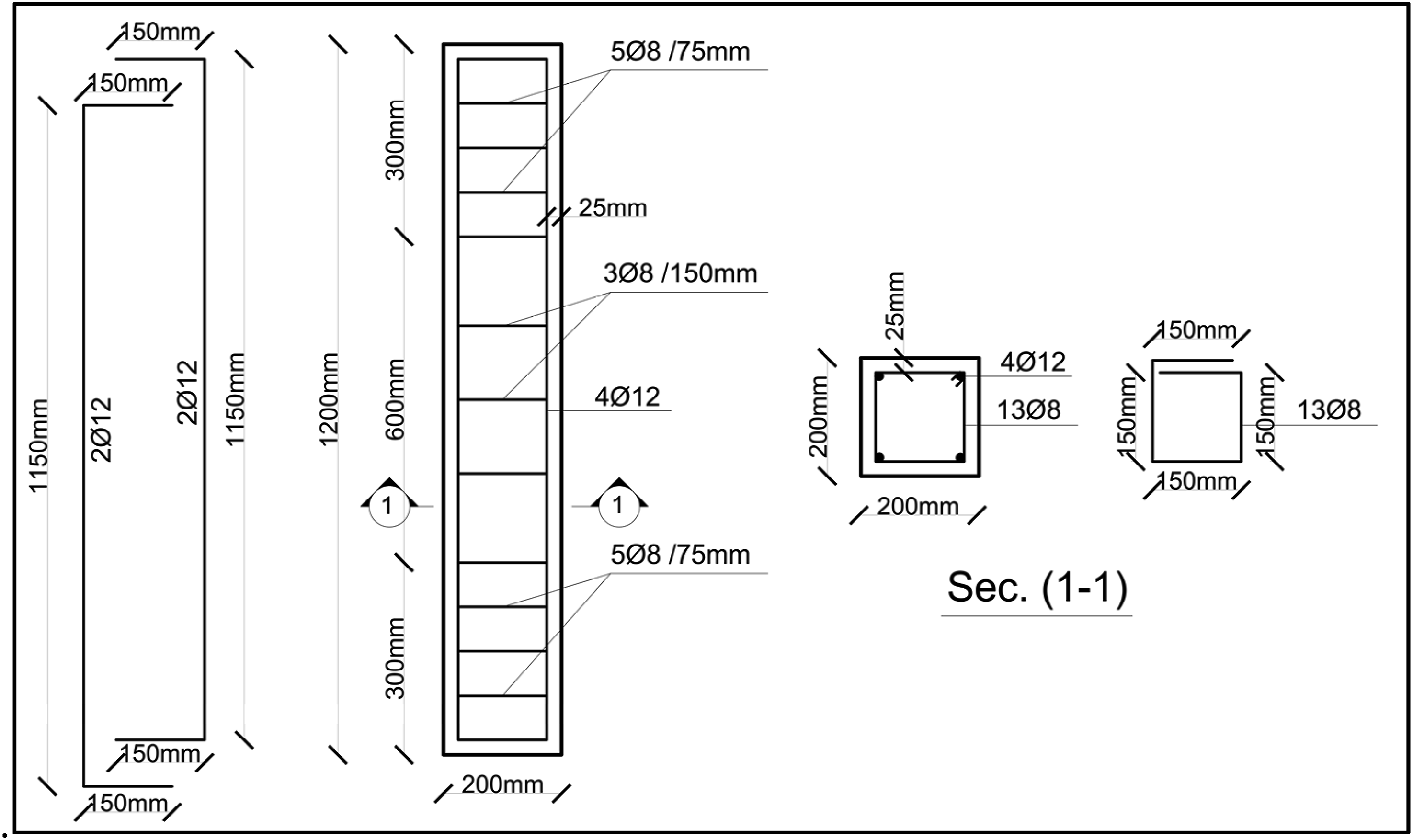
Dimensions and reinforcement details of control specimen (C1).
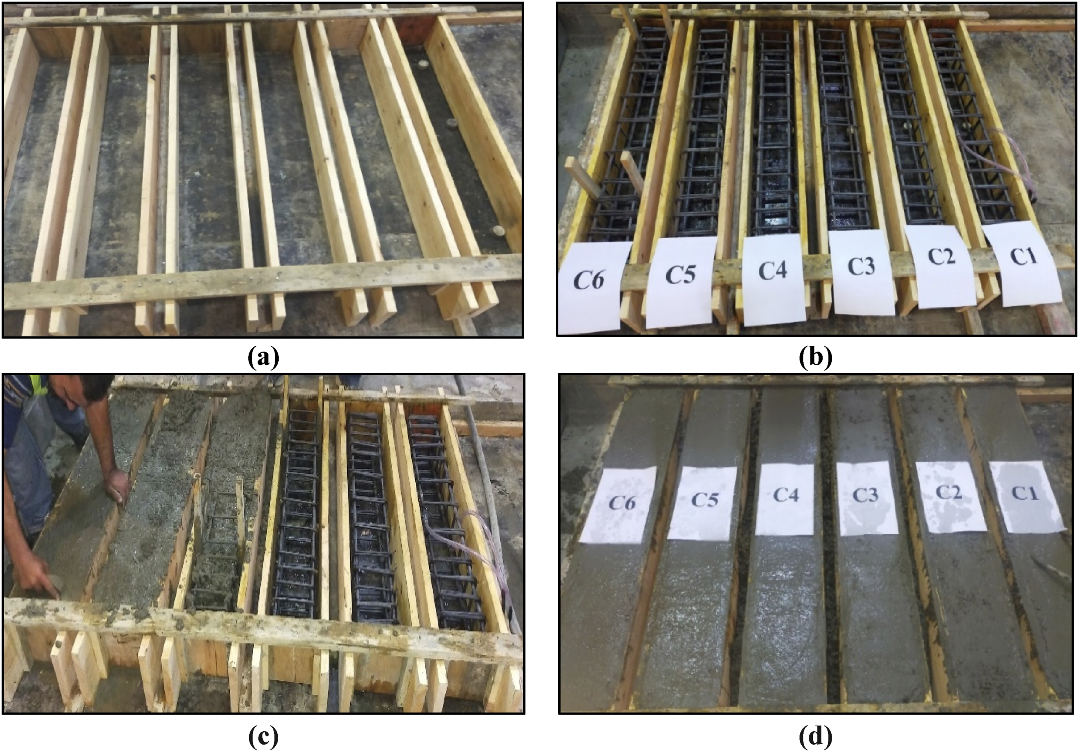
Specimens’ preparations: (a) Formworks for the column specimens; (b) The reinforcement inside formwork; (c) During casting concrete process; (d) After pouring process.
Fire application on the specimens
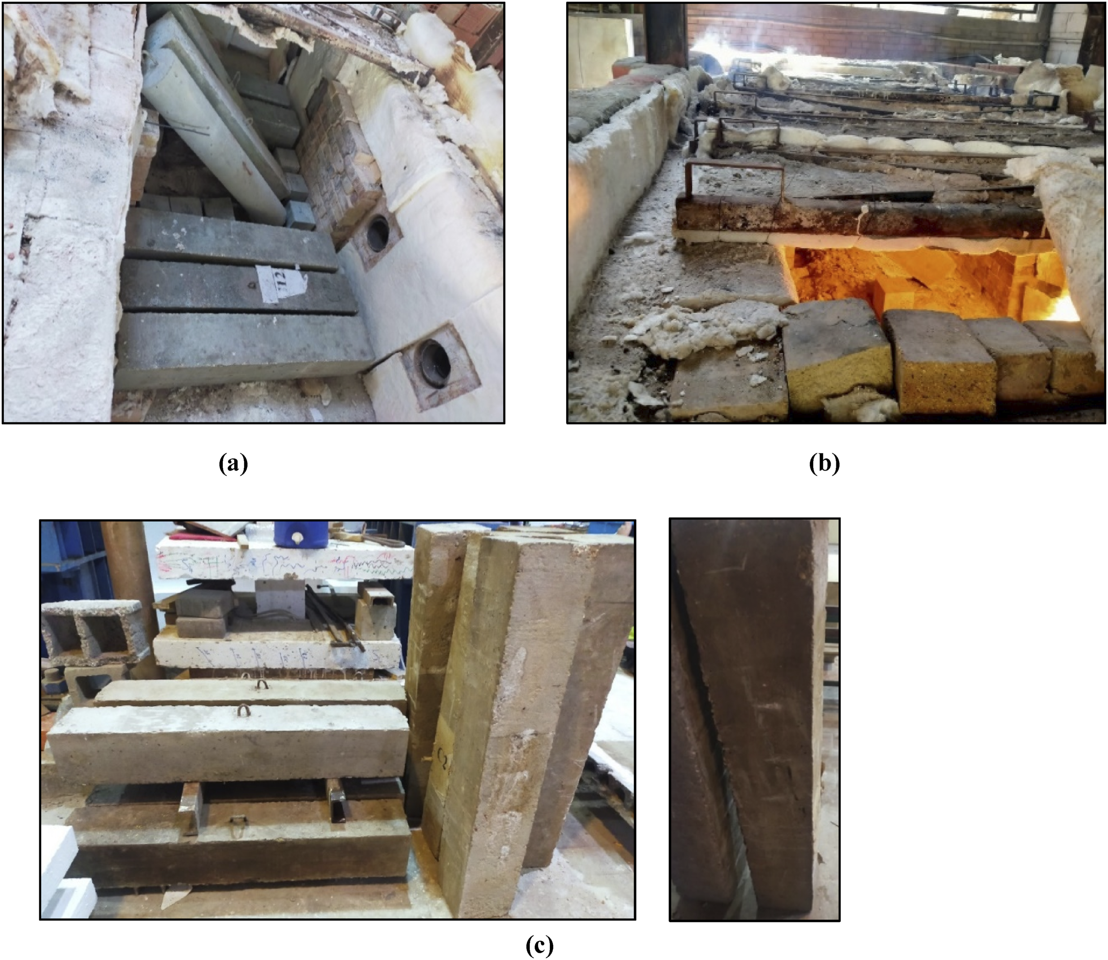
Elevated temperature was achieved using an oven, existed in the Fire Laboratory at Housing and Building National Research Center (HBRC) with internal dimensions of (2000*3000*1000) mm, equipped with four diesel-powered flames working in one direction. It was connected to an electrical panel for temperature control. On the opposite side, there is a chimney, and two thermocouples are positioned at equal distances. The oven is insulated on all four sides with ceramic fiber to prevent flame spread. The specimen’s temperature was raised from ambient to a target temperature of 400°C and 600°C at different stages. After reaching the target temperature, specimens were kept in the oven to ensure a uniform temperature distribution, mimicking real conditions, and then allowed to cool naturally with ambient air. Figure 4 illustrates the oven, control panel and the oven flames. Fire exposure caused surface changes in concrete, including ash, soot, color shifts (light grey to pink at 400°C, dark grey at 600°C), and texture variations. High temperatures led to cracking and spalling in reinforced concrete columns, altering their appearance. Figure 5 illustrates the fire process. The oven parts: (a) The oven from inside and outside; (b) The temperature electrical control panel; (c) The flames of the oven. The process of fire: (a) The specimens inside the oven before the fire; (b) The specimens inside the oven during the fire; (c) The specimens after the fire.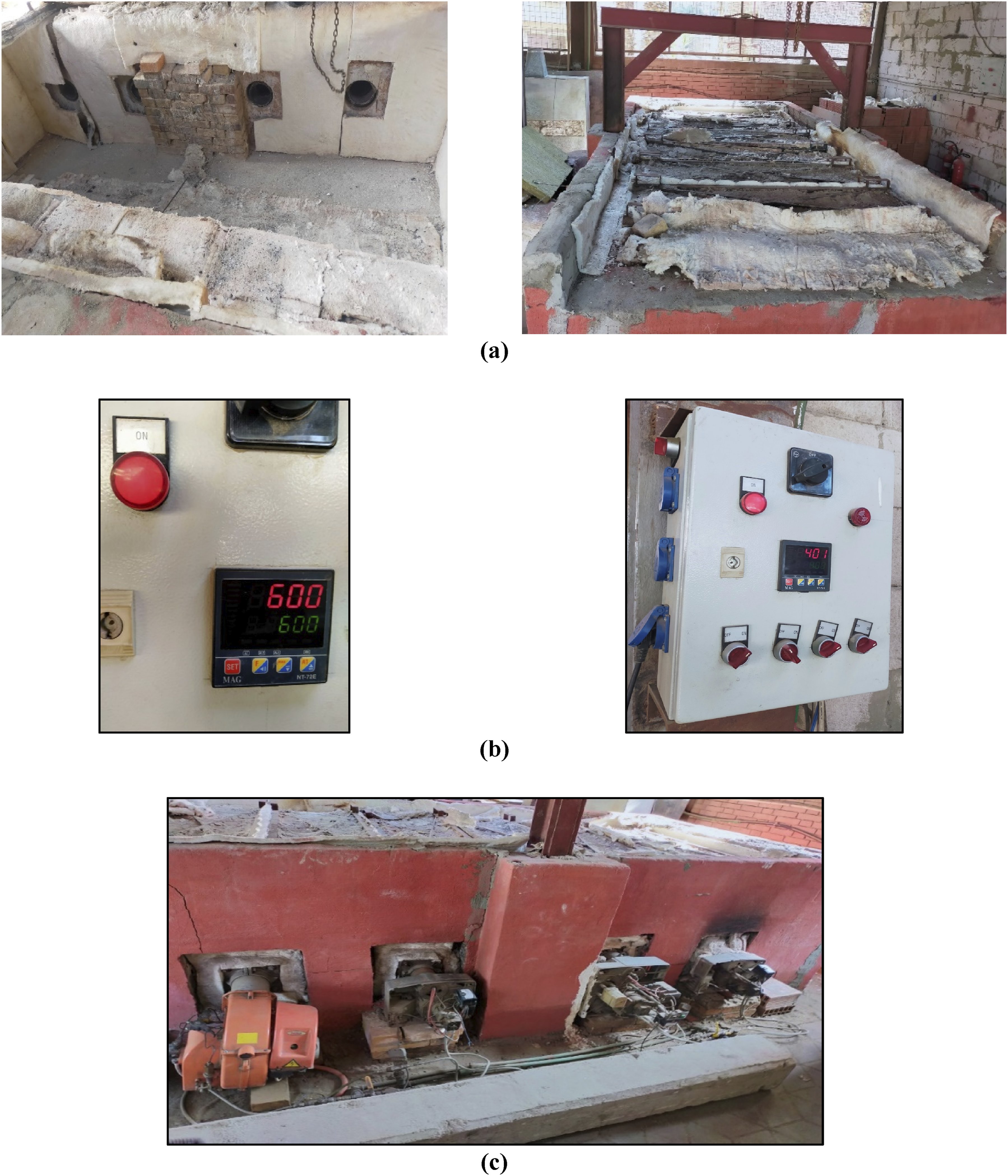
Material properties
Concrete Mixture of the RC columns.
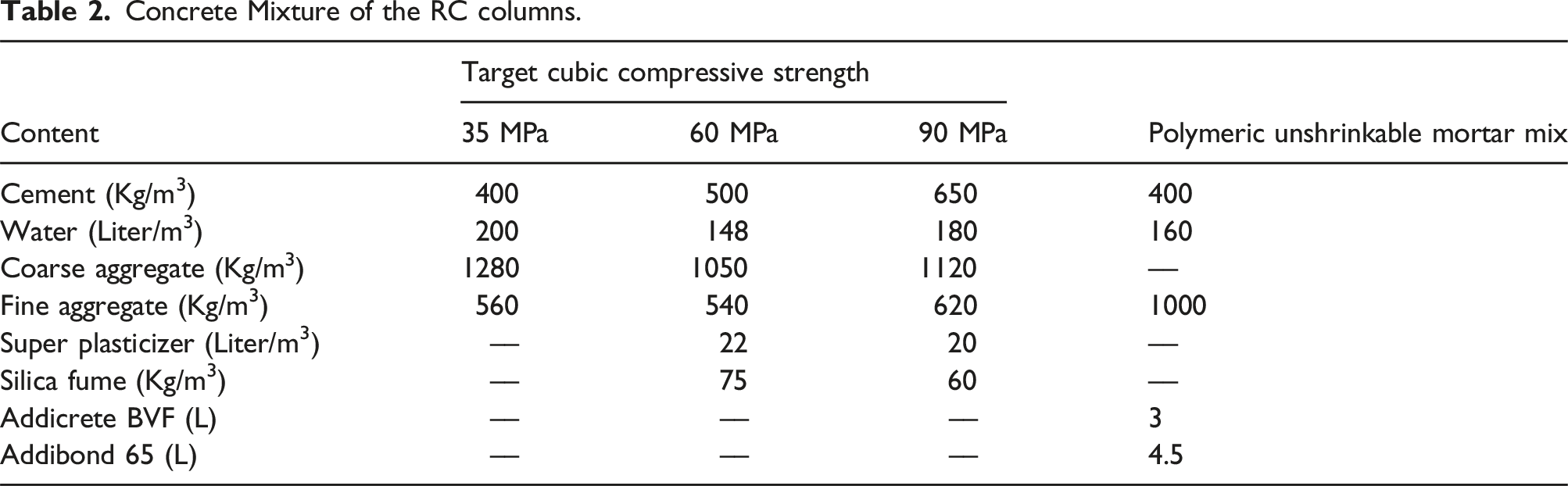

Test Setup: (a) Compressive cylinder test; (b) Tensile test of reinforcing bars.
The CFRP fabric studied is SikaWrap-230 C with 0.129 mm thickness. It has tensile strength of 3.2 GPa and 220 GPa modulus of elasticity, as specified by the manufacturer’s data sheet. Sikadur-330 acted as a primer resin with bond strength of 4 GPa, tensile strength of 30 GPa, and modulus of elasticity of 4500 GPa. Kemapoxy 165 was used as an adhesive for steel and concrete, while Addibond 65 bonded new concrete to old. Steel grades were 40/60 for main reinforcement, 24/36 for stirrups, and 37 for angles and strips. The mechanical properties of the reinforcing bars were determined experimentally in accordance with (ASTM A615/A615M-16, 2016), as shown in Figure 6(b). The tensile yield strengths at ambient temperature for bar diameters of 8 mm and 12 mm were measured at 235 MPa and 410 MPa, respectively, with ultimate values of 370 MPa and 615 MPa. Silica Fume is utilized in concrete mix with a bulk density of 586 kg/m3. ViscoCrete®-3425 is a high-range water-reducing admixture designed to enhance the workability and performance of concrete by improving its flow characteristics and reducing water content.
Strengthening using RC jacket
The column dimensions were enlarged to 250 × 250 mm using the RC jacket technique. The steel reinforcement included: Firstly, four 12 mm diameter main bars, Secondly, 13 8 mm diameter stirrups-five spaced at 7.5 cm within the first and last 30 cm, and three spaced at 15 cm in the middle, and Lastly, seven 12 mm diameter L-shaped shear connectors per side with a 70 mm development length as shown in Figure 7. The process involved removing the concrete cover to the stirrups’ surface, as illustrated in Figure 8(a), placing new stirrups around the main bars as in Figure 8(b)), drilling holes for shear connectors as illustrated in Figure 8(c), and securing them with Kemapoxy 165 adhesive as shown in Figure 8(d). A strain gauge was installed in the main reinforcement as illustrated in Figure 8(e). Addibond 65 adhesive was applied to bond old and new concrete before pouring the new concrete as shown in Figure 8(f). Following the application of the adhesive and before it dries, the new concrete for the RC jacket is poured, as shown in Figure 8(g). Schematic RC jacket reinforcement. Stages of strengthening using RC jacket: (a) Removing the concrete cover for RC jacket; (b) Fixing of RC jacket reinforcement; (c) Drilling holes for RC jacket; (d) Secure the shear connectors into the holes drilled at the sides of the columns; (e) Installation the strain gauge; (f) Coating specimen with addibond 65; (g) Pouring concrete for RC jacket.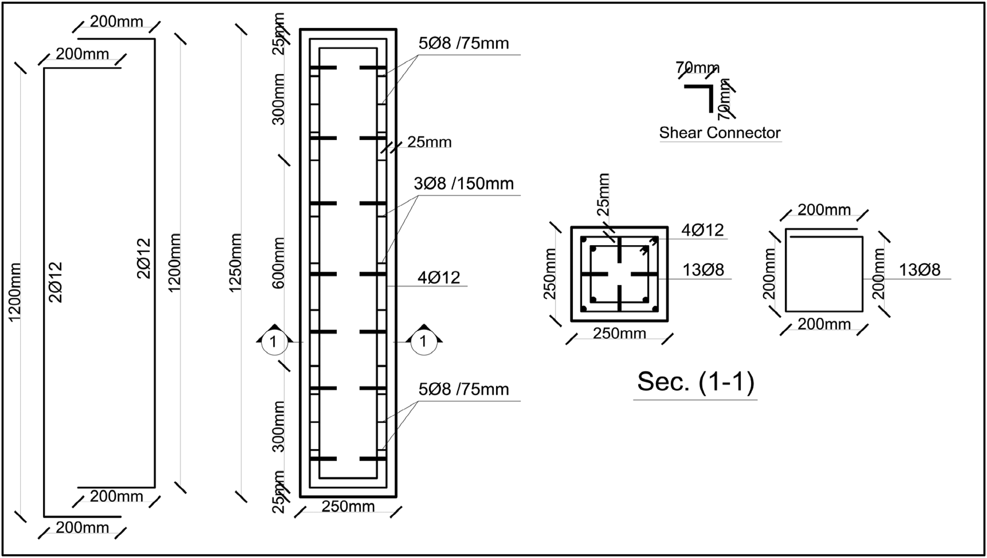

Strengthening using steel jacket
Steel jackets were prepared through a detailed process. First, the concrete cover was removed as per the RC jacket technique shown in Figure 9(a). Polymeric non-shrink mortar was applied to the edges of the columns to smooth the specimen corners and facilitate the installation of steel angles, ensuring full contact, as illustrated in Figure 9(b). After the mortar had dried, adhesive Kemapoxy165 was spread along the column edges and inside the steel angles. The steel angles were then positioned and pressure was applied using shuttering clamps to eliminate any voids, as depicted in Figure 9(c). Following a 24-h drying period, markings were made on the steel angles to indicate the positions of the steel plates. The steel angles were then welded to the column stirrups and the steel plates using 3 mm diameter welding electrodes, as shown in Figure 9(d). Strain gauges were then placed on the steel angles, and the adhesive component Addibond 65 was applied to bond the old and new concrete, which had the same cubic characteristic strength of 35 MPa as old concrete, as seen in Figure 9(e)–(g). Stages of strengthening using steel jacket: (a) Removing the concrete cover and forming path for steel angles; (b) Placing polymeric mortar at the edge of columns; (c) Fixing of steel angle with kemapoxy 165; (d) Fixing and welding of angles and plates; (e) Placing strain gauges on steel angles; (f) Applying addibond 65 and pouring concrete for steel jacket; (g) After pouring the new concrete.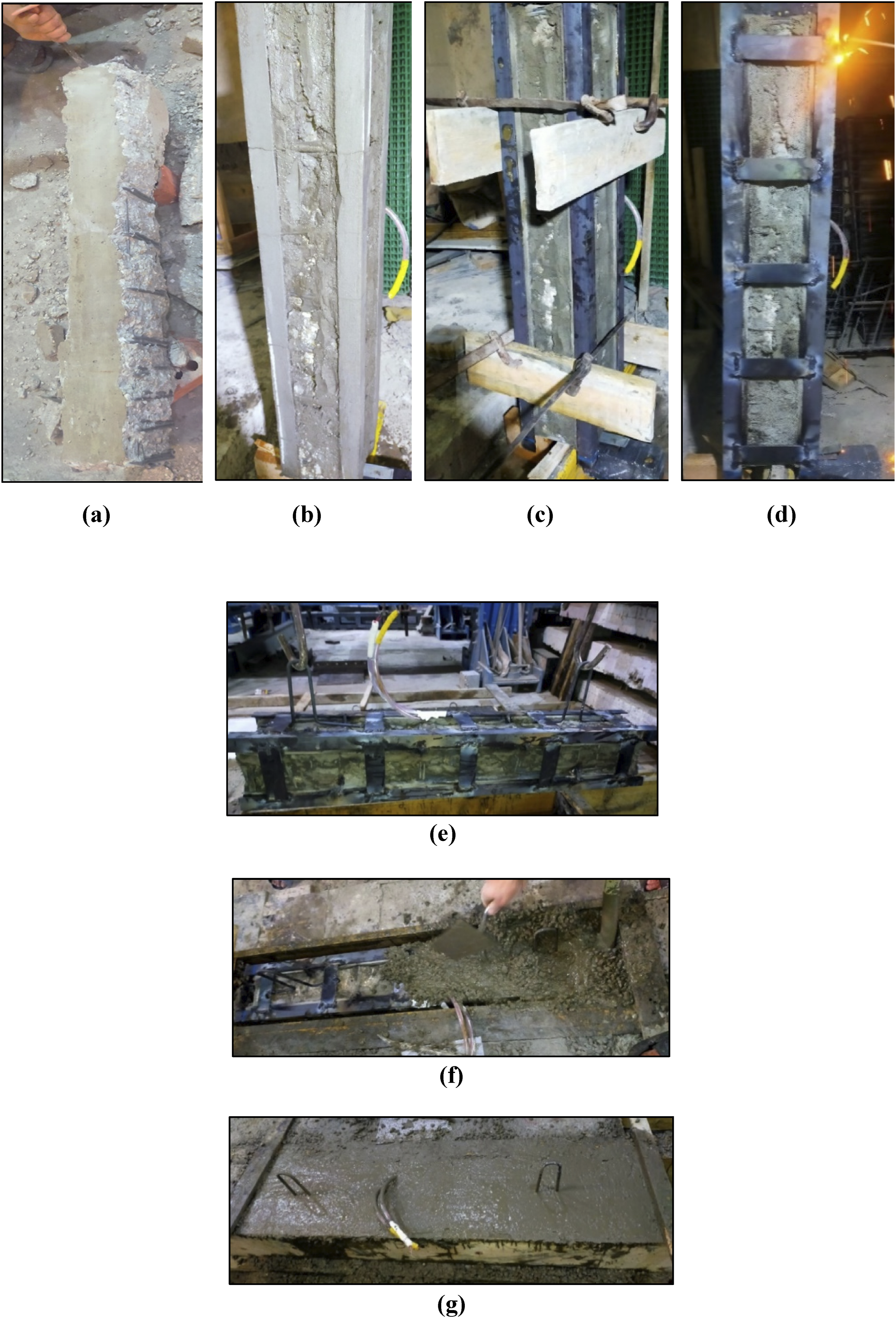
Strengthening using CFRP wrapping
Initially, CFRP sheets were cut to specific dimensions, ensuring a 150 mm overlap in the wrapping direction with identical sheet pieces and a 150 mm overlap with the other fabric. In the process of strengthening with CFRP wrapping, the surface of the columns underwent preparation, involving cleaning and softening the concrete surface, and smoothing the corners into a rounded shape using coarse sanding, as presented in Figure 10(a). Following the preparation of the surface, an adhesive material, determined according to manufacturer specifications, was brushed onto the column surface. Subsequently, the CFRP sheets were positioned and pressed firmly using a paint roller to remove any air pockets, as depicted in Figure 10(b)–(d). Stages of strengthening using CFRP sheets: (a) Cleaning the concrete surface; and forming rounded corners; (b) Applying adhesive material prior and after wrapping of CFRP sheets; (c) Pasting CFRP fabrics; (d) Extracting the voids using painting roller.
Test setup and instrumentation
The tests were carried out at the concrete research laboratory at the faculty of engineering, Cairo University. The specimens were subjected to loading using a compression testing machine with a capacity of 5000 kN until failure occurred. The applied loading condition was axial loading, as in Figure 11(a). The shown test setup matches that described by Wang et al. (2025). Since hinge supports at the columns’ ends may be unstable, cause stress concentrations and unforeseen load paths, and not simulate reality, they were not used. Mid-height transverse displacement was traced by placing four LVDTs (100 mm stroke) at the middle height of the specimens to ensure that no buckling occurred during the test, which will be confirmed when demonstrating the failure mode in Section 4.1. Axial displacement was also measured using one vertically installed LVDT at the upper loading head. Figure 11(b) shows the position of each LVDT. The theoretical load of the columns was estimated from (ACI 318-19, 2019). Test Setup: (a) axially loading; (b) Locations for the LVDTs.
Results and discussion
Results of the Tested columns.
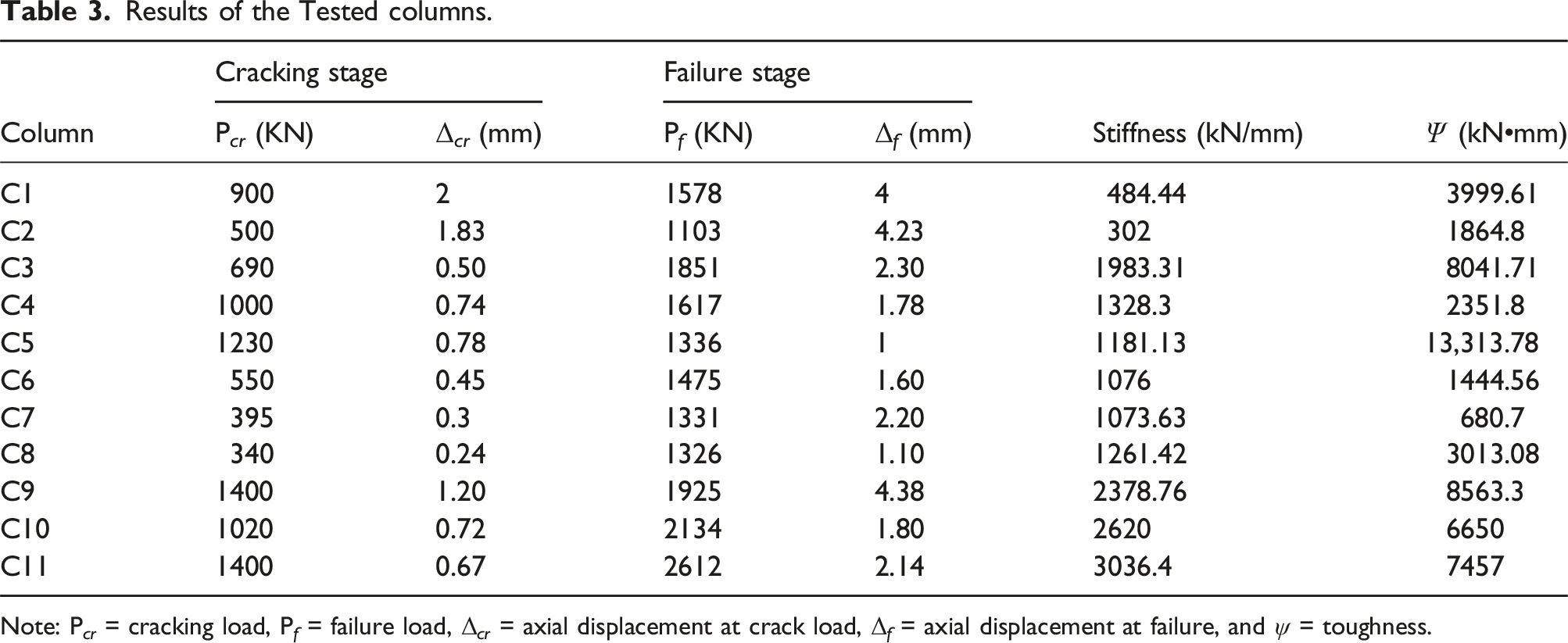
Note: P cr = cracking load, P f = failure load, Δ cr = axial displacement at crack load, Δ f = axial displacement at failure, and ψ = toughness.
Crack pattern and failure mode
In general, the main modes of failure observed are cover separation and concrete crushing. Figure 12 illustrates the cracking patterns and failure modes of the tested columns. In the control specimen C1, diagonal cracks formed, and failure occurred in the lower third of the column. In the reference specimen C2, cracks initiated early and extended to the middle of the column, becoming wider and more distinct before a sudden failure at the top. For column C3, cracks developed low on the column, with failure occurring at the top. Column C4 exhibited more cracks than C3; the concrete cover separated until it exposed the steel jacket, and then failure progressed from the top to the middle of the column. In column C5, the failure began as a compression failure just beyond the CFRP sheets at mid-height. This was followed by the rupture of the sheets and subsequent splitting of the concrete cover. In columns C6, C7, and C8, cracks were wider, more pronounced, and appeared earlier, often leading to sudden failure. The failure occurred in the lower third of the column for specimens C6 and C8, while in specimen C7, failure took place at mid-height and was accompanied by buckling of the main steel reinforcement. In column C9, small cracks spread throughout the column, leading to cover separation and concrete crushing at the top. In columns C10 and C11, cracks appeared later than in the previous specimens and were wider and more visible. Failure in these columns also occurred in the lower third of the column. Failure modes of tested specimens.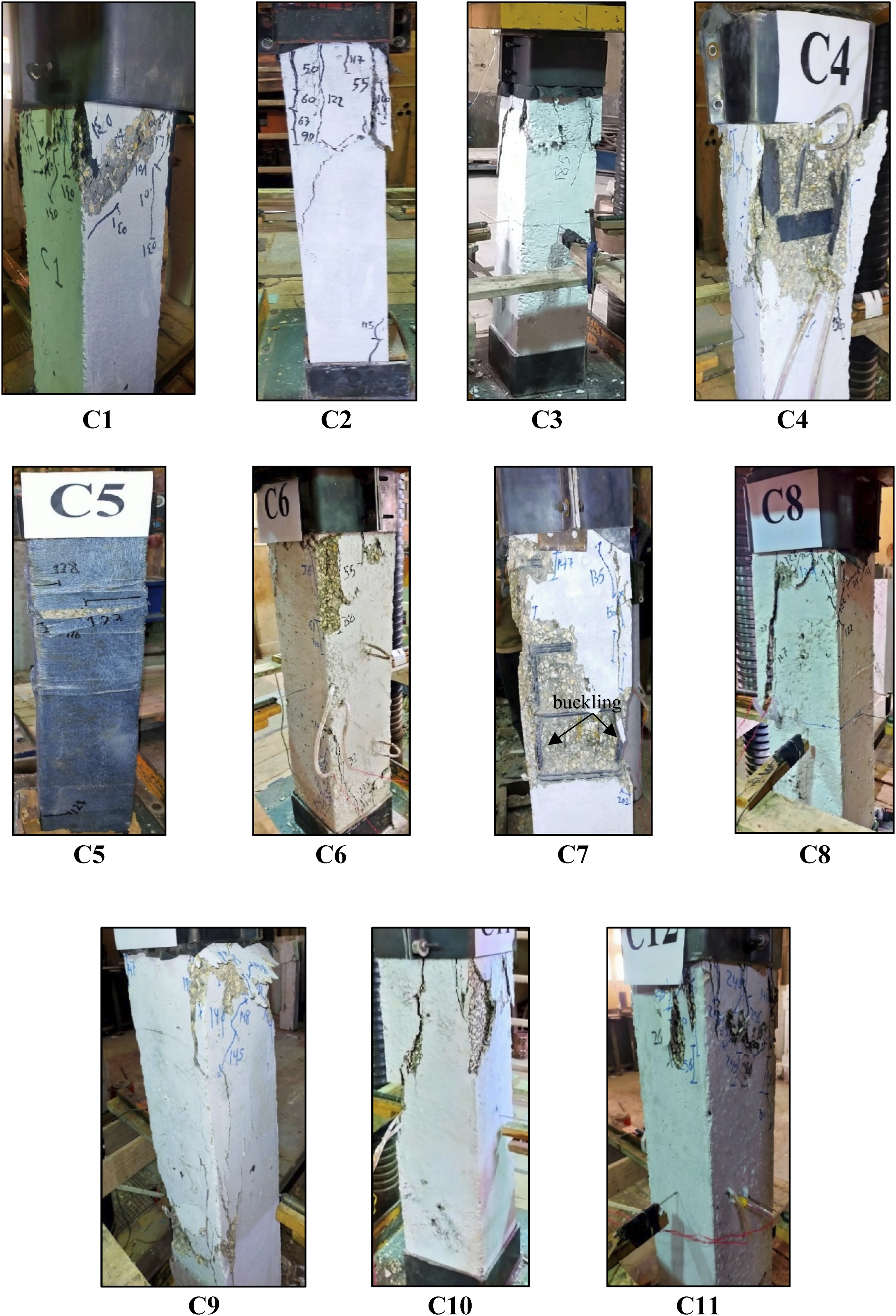
Effect of elevated temperature
The study compared the performance of a control column (C1) not exposed to elevated temperatures with a reference column (C2) that was exposed to 400°C. Cracking in C2 occurred earlier, at a load of 500 kN, compared to 900 kN for C1. Elevated temperature reduced the ultimate load by 30%. The axial displacement at ultimate load for C2 increased by 5.8% compared to C1, due to elevated temperature-induced damage reducing stiffness by 37.7%. Additionally, the toughness, represented by the area under the load-axial displacement curve, decreased by 53.4% in C2. Figure 13(a) shows the axial displacements for the two columns C1 & C2 Load-axial displacement curves.
Effect of elevated temperature duration
The effect of elevated temperature exposure on columns C3, C6, and C7 resulted in significant deterioration. Pre-cracks were observed, and the first cracking load decreased to 690, 550, and 395 kN, respectively. Compared to C3, which was exposed to heat for 90 minutes, longer exposure durations of 120 and 150 minutes reduced the ultimate load capacity by 25.5% and 38.9%, respectively. The axial displacements at ultimate load also decreased by 30.4% for C6 and 4.4% for C7, as shown in Figure 13(b). Additionally, toughness, represented by the area under the load-axial displacement curve, dropped by 82% for C6 and 91.5% for C7, while stiffness decreased by approximately 45.8% for both C6 and C7 compared to C3.
Effect of elevated temperature degree
Raising the temperature to 600°C significantly affected the performance of column C8, leading to deterioration in pre-cracks and a reduction in the first cracking load to 340 kN, compared to 690 kN for C3, which was exposed to 400°C. The ultimate load capacity of C8 decreased by 28.4%, and the axial displacement at the ultimate load dropped by 52.5%, as shown in Figure 13(c). Additionally, the toughness, represented by the area under the load- axial displacement curve, decreased by 62.5%, while stiffness decreased by 36.4% for C8 relative to C3.
Effect of strengthening techniques
Figure 13(d) compares the performance of strengthened axially loaded columns with a reference column (C2). Strengthening using RC jackets, steel jackets, and CFRP wrapping increased the ultimate load capacity by 67.8%, 46.6%, and 21.12%, respectively. Axial displacements at the ultimate load decreased by 45.6%, 57.9% and 76.4% for C3, C4 and C5, respectively. Toughness improved significantly, with CFRP strengthening showing the highest increase (614%) due to enhanced confinement, followed by RC jackets (331.2%) and steel jackets (26.12%). Initial stiffness also increased by 556.7%, 339.8%, and 291% for RC jackets, steel jackets, and CFRP wrapping, respectively. In contrast to unstrengthened specimens (C1 and C2), all the other strengthened specimens exhibited post-peak softening behaviors, demonstrating that the used strengthening techniques were successful in improving both the ductility and the load-axial displacement response. This may be because all the strengthening techniques effectively confined the micro cracks developed by the effect of elevated temperature, which is in line with the results of Khalil et al. (2025).
Effect of concrete compressive strength
Figure 13(e) shows that the axial displacement corresponding to the ultimate load decreased by 21.7% and 7% for columns C10 and C11, respectively, compared to column C3. The HSC columns increased the ultimate load capacity by 15.3% and 41.11%, while the area under the load-axial displacement curve decreased by 17.3% and 7.3%. Furthermore, the initial stiffness increased by 32% and 53% for C10 and C11, respectively.
Effect of concrete cover
The effect of enlarging the concrete cover increased the ultimate load capacity by 4 %. Figure 13(f) shows that the axial displacement corresponding to the ultimate load increased by 90.4%. The area under the load-axial displacement curve, representing toughness, increased by 6%, and the initial stiffness increased by 20% for C9 compared with C3.
Normalized load- axial displacement curves
The specimens strengthened with RC jacket and steel jacket increased the dimensions of the columns from 200 × 200 mm to 250 × 250 mm. To ensure a reliable comparison between specimens in cases of axial loading, it is necessary to conduct normalized load-axial displacement curves, accounting for the 64 % increase in dimensions with the RC jacket and steel jacket techniques. This normalization also eliminates the impact of size changes. Consequently, the strengthened specimens with increased dimensions were assumed to retain the original 200 × 200 mm dimensions of the un-strengthened specimen and their load-axial displacement curves were normalized accordingly. To assess the impact of altering the cross-sectional area, a reduction factor for the reinforced specimens was determined using the equation (1) for the axial strength of compression members following the American Institute Code (ACI 318-19, 2019), as detailed below: Normalized load-axial displacement curves for columns C2, C3, C4 and C5.

Finite element analysis (FEA)
The finite element modeling process using ABAQUS/CAE 6.14 to study the behavior of elevated temperature-exposed, strengthened reinforced concrete columns. It explains the steps to create models, analyze load-displacement responses, and determine ultimate load capacities. Numerical results, compared with experimental data from 11 specimens, demonstrate good agreement.
Material properties
In ABAQUS, both concrete and steel angles were modeled using an 8-node solid element, C3D8R, while conventional steel bars were modeled using T3D2 elements. Structured meshing was employed for this model. A four-node shell element with reduced integration (S4R) was used to simulate the CFRP wrapping sheets, enabling the representation of their thin, plate-like properties. The Concrete Damaged Plasticity (CDP) model is a versatile framework for simulating the behavior of reinforced or unreinforced concrete and other quasi-brittle materials under various loading conditions. It incorporates tensile cracking and compressive crushing as the primary failure mechanisms and accounts for material degradation in tension and compression (Lu et al., 2019).
Following ABAQUS’s recommendation, the CDP’s plasticity parameters were the shape coefficient 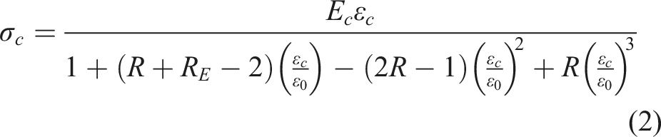

The embedded region modeling approach was used, where reinforcement is modeled with truss elements requiring only the bar cross-sectional area as input. The steel’s constitutive behavior is represented by an elastic-perfectly plastic model. Steel properties include a yield stress 450 MPa, Young’s modulus of 220 GPa and Poisson’s ratio of 0.30. A perfect bond is assumed between concrete and steel reinforcement, which includes 8 mm and 12 mm diameter steel bars.
Interaction between parts
The embedded element technique was used to simulate the interaction between the embedded reinforcement bars and the adjacent concrete. The embedded techniques considered the dowel action and slip bond by introducing the tensile behavior of concrete. The interaction between the interior steel reinforcement and the concrete column as well as the interaction between the steel reinforcement jacket and the concrete jacket simulated using the embedded element constraint. The interaction between the concrete column and the concrete jacket was simulated using the tie constraint mechanism.
Mesh configuration, loading, and boundary conditions
In ABAQUS, concrete was modeled using an 8-node solid element, C3D8R, while conventional steel bars were modeled using T3D2 elements. Structured meshing was employed for this model. As the choice of finite element mesh may impact results, a mesh sensitivity analysis was conducted to highlight the robustness of numerical model parameters. Therefore, three finite element meshes were tested with 25 mm, 50 mm, and 75 mm edge lengths. Hence, the effect of these meshes on the load-axial displacement was first investigated. Figure 15 shows the displacement variation for different mesh sizes in column C3. A mesh of 50 mm length was selected to provide the required level of accuracy, less computational time, along with an adequate number of meshes. The loading condition was simulated with a concentrated load on the reinforced concrete (RC) column. Figure 16 demonstrates that all translational displacements of the nodes along the center line at the loading plates were constrained in the x, y, and z directions, except for the z-direction translation of the top plate, which remained unrestricted. The rotation in the x and z axes was restricted at the upper and lower plates. Axial displacement variation for specimen C3 compared to representative element meshes. FEA model preparation for RC column: (a) The Model mesh and the element dimensions; (b) Details of reinforcement; (c) Distribution of the steel angles and the steel plates along for specimen C4; (d) Loading and supports condition for specimen model.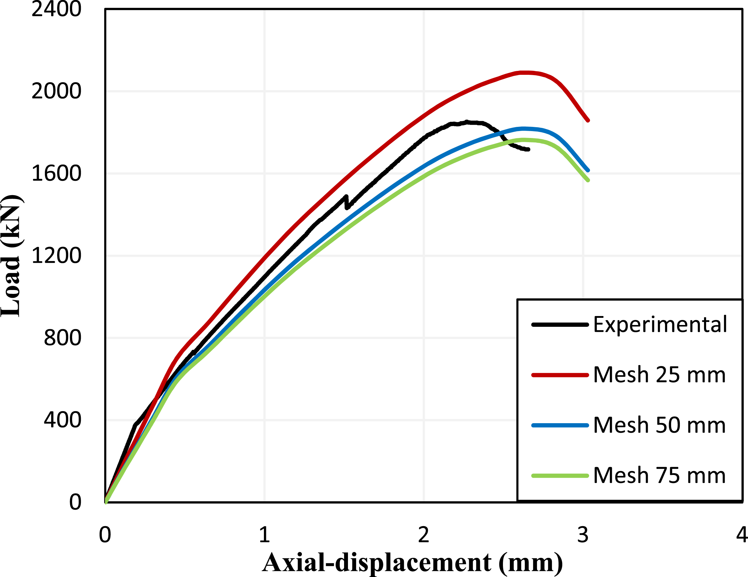

Validations of the FE models
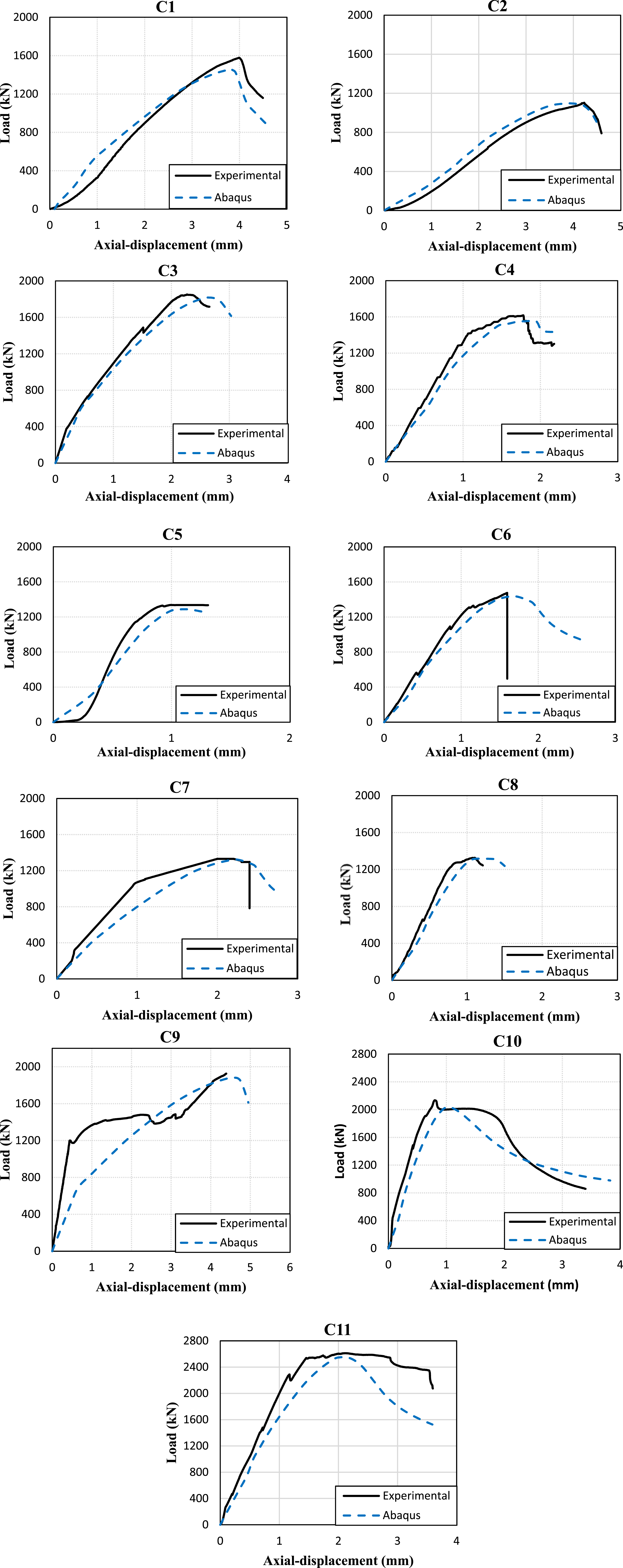
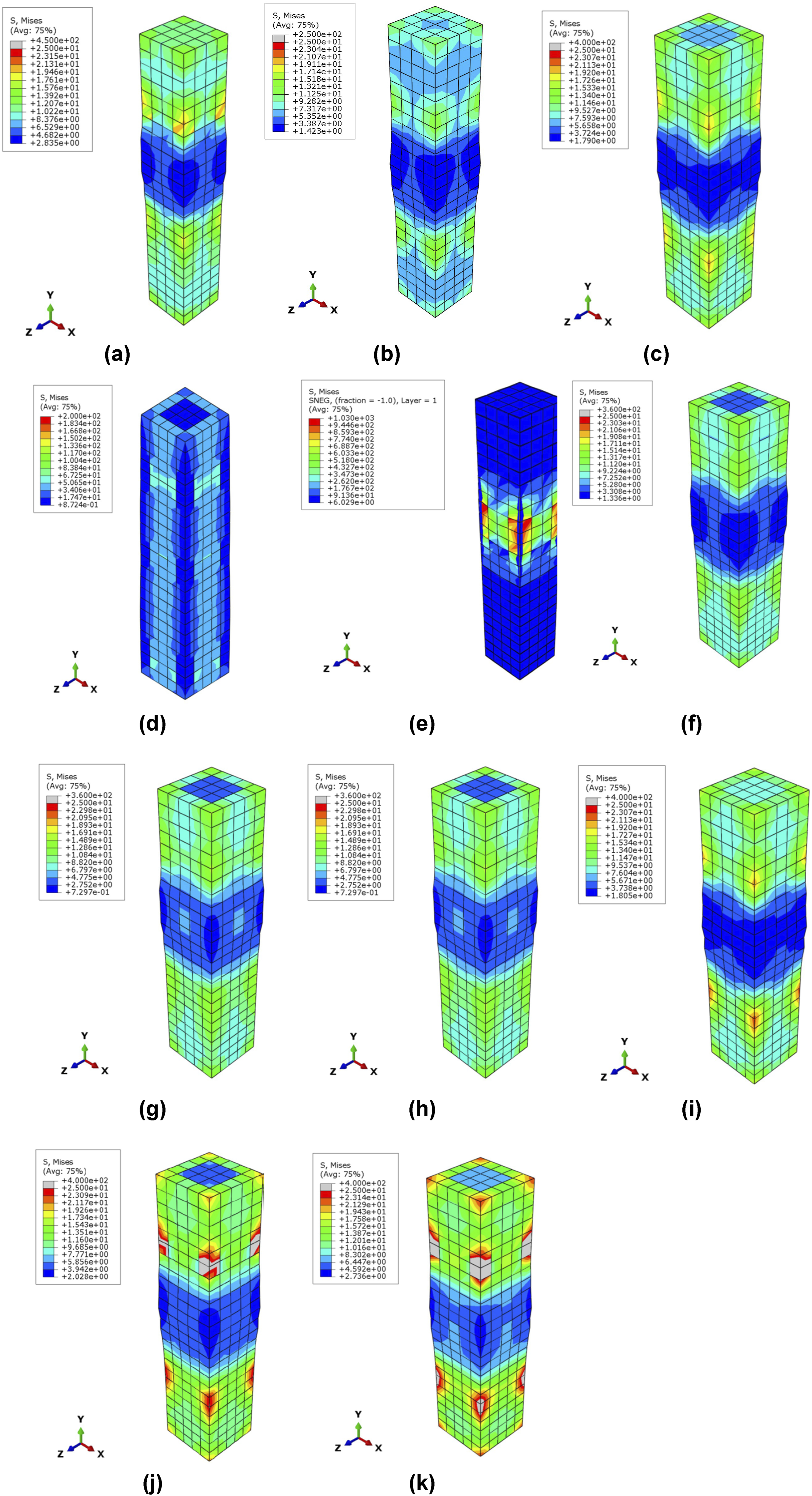
To validate the experimental results, the finite element (FE) results were compared with the experimental data. This comparison was conducted to confirm that the convergence criteria were suitable for the tested column specimens. The elevated temperature scenario was simulated in ABAQUS by modifying the concrete properties and reducing its strength. The actual stress-strain curve of the concrete after temperature exposure was incorporated, with an average compressive strength of 28 MPa. Comparisons were made regarding the typical failure modes and the load–displacement relationships. Figure 17 presents a comparison between the experimental results and the numerical outcomes obtained from ABAQUS. Figure 18 illustrates the comparison in load–displacement between the experimental results and the numerical model results. Figure 19 shows the stresses at the failure load. A strong correlation was observed between the FEA results and the experimental data. Comparison between the experimental results and numerical results from ABAQUS. Comparisons of the FEA with the experimental load-axial displacement curves. Stresses at failure load for: (a)Specimen C1; (b)Specimen C2; (c)Specimen C3; (d)Specimen C4; (e)Specimen C5; (f)Specimen C6; (g)Specimen C7; (h)Specimen C8; (i)Specimen C9; (j)Specimen C10; (k)Specimen C11.
Conclusions
Taking into account the results from the previous sections and the parameters analyzed, the following conclusions can be made: 1- The concrete’s compressive strength reduced by 20% after being exposed to elevated temperature for 90 minutes. This reduction increased to 32% after 120 minutes of exposure, and further to 44% after 150 minutes. 2- When exposed to a temperature of 600°C, concrete experiences a 50% reduction in its strength. Additionally, in the case of HSC, it undergoes a decrease of approximately 45%. 3- In case of exposure to elevated temperature, the ultimate load capacity was decreased by 30% followed by a reduction in the absorbed energy and stiffness. 4- The extended fire period will significantly reduce load capacity by 25.5% for 120 minutes and by 38.9% for 150 minutes, thereby impacting both toughness and stiffness. 5- RC columns exposed to 600°C experience a 28.4% greater reduction in ultimate strength (determined based on failure load) compared to RC columns exposed to 400°C. 6- RC jacket technique showed the higher value in ultimate load, axial displacements and initial stiffness, in spite of the lower cost value. 7- The HSC improved ductility and increased the ultimate load capacity by 15.3% and 41.11%, respectively, while the area under the load-axial displacement curve decreased by 17.3% and 7.3%. Furthermore, the initial stiffness increased by 32% and 53% for 60 MPa and 90 MPa, respectively. 8- Increasing the concrete cover to 35 mm instead of 25 mm increased the ultimate load, strength and stiffness by 4%, 6% and 20% respectively. 9- There was a good agreement between experimental results and ABAQUS results from the difference between numerical and experimental results was within 5%. 10- The practical implications of the findings for real-world structural engineering applications may help create more thorough design guidelines for RC columns exposed to elevated temperatures that improve structural integrity as well as identify the most cost-effective strengthening techniques for such elements.
Recommendations for future studies
Although this study does provide some useful conclusions, further research is needed to fully understand the performance of repaired RC columns subjected to elevated temperatures. Additional study in this field should focus on the following areas: 1. It is important to explore the effectiveness of other cooling methods, such as natural air cooling, water cooling, fire-fighting foam cooling, and dry powder cooling. 2. Additional strengthening techniques, such as near-surface mounted FRP and hybrid systems, should be evaluated. 3. An experimental program on strengthened RC columns after exposure to higher elevated temperatures with rapid heating rates should be conducted to simulate more severe fire scenarios.
Footnotes
Acknowledgments
The experimental program was carried out at the concrete laboratory, Faculty of Engineering, Cairo University. Elevated temperature was achieved using an oven existed in the Fire Laboratory at Housing and Building National Research Center (HBRC). Technicians and lab. staff are acknowledged for their great help with day-to-day problems.
Declaration of conflicting interests
The author(s) declared no potential conflicts of interest with respect to the research, authorship, and/or publication of this article.
Funding
The author(s) received no financial support for the research, authorship, and/or publication of this article.
