



Abstract
This study proposes a bidirectional gas-spring damper (BGD) to reduce excessive wind-induced vibrations and fatigue damage in large-span transmission tower-line system (LTTS), thereby extending its service life. A detailed numerical model of a LTTS is developed based on actual engineering project, the configuration parameters of BGD for wind-induced vibration control are designed, and its working principle and preliminary design method are introduced. The control performance of the BGD in mitigating wind-induced vibration responses of the LTTS is investigated, and its corresponding configuration parameters are optimized. Stress response and fatigue performance analyses are conducted for the uncontrolled and controlled LTTS, and the life-prolonging effectiveness of the dampers is quantified and discussed. Results demonstrate that the BGD achieves vibration reduction ratio similar to that of a tuned mass damper (TMD) but with a smaller stroke and wider damping frequency band. BGD’s frequency ratio is suggested to be between 0.9 and 1.0, with an initial gas pressure of 0.9
Keywords
Introduction
Large-span transmission tower-line system (LTTS) is essential for long-distance, high-capacity electricity transmission and efficient distribution. However, their lightweight structure, high flexibility, and low damping make them vulnerable to wind-induced vibrations (Xie and Zhu, 2011; Tian et al., 2018; Fu et al., 2023; Zekavati Ali et al., 2023), which compromise structural safety and reliability and significantly increase maintenance costs. Statistics indicate that most transmission line system collapses worldwide are due to strong winds and long-term wind-induced vibrations (Li et al., 2020), with fatigue fractures being a primary cause of steel structure destruction (Cheung and Li, 2003). Current research has analyzed the fatigue performance of transmission towers (Havard and Perry, 2000; Klinger et al., 2011; Tian et al., 2020), conductors (An et al., 2019; Ruan et al., 2021), and connectors (Chen et al., 2022; Lalonde et al., 2018), highlighting stress amplitude as a key factor in fatigue destruction, with mean stress positively influencing fatigue damage.
Relevant studies have shown that reducing structural response by 15% can more than double the structure’s service life and significantly lower maintenance costs (Ou et al., 2007; Anwar et al., 2019; Su et al., 2023; Zhu et al., 2023). Vibration control technology, which mitigates dynamic responses without damaging the structure, is effective for this purpose. Traditional linear dampers, such as tuned mass damper (TMD), are widely used for wind-induced response control in engineering structures (Sun et al., 2022). For transmission line systems, Balendra et al. (1995) investigated the performance of TLCD in mitigating tower vibrations under wind loads. Tian et al. (2012) utilized TMD for mitigating the wind-induced vibration response of LTTS. Lei et al. (2023) proposed an eddy current TMD for controlling low-frequency vibrations in transmission towers under strong winds. Lou et al. (2022) employed a torsional TMD to reduce the galloping responses of transmission lines. Despite their mature design methods, linear dampers face limitations like narrow frequency bands and large working strokes.
Consequently, various nonlinear dampers have been proposed, including spring pendulum damper (Cuvalci and Ertas, 1996; Matta and De Stefano, 2009; Zhang et al., 2015; Soltani and Deraemaeker, 2021), pounding tuned mass damper (Tian et al., 2017; Wang et al., 2021; Zhang et al., 2013; Tian et al., 2019), nonlinear energy sink (Vakakis, 2001; Wang et al., 2015; Habib and Romeo, 2017; Zuo and Zhu, 2022), shape memory alloy (SMA) damper (Mishra et al., 2013; Tian et al., 2019; Tian et al., 2020), and nonlinear gas-spring damper (Hochrainer, 2015; Rong and Lu, 2021, 2022; Rong et al., 2023; Rong et al., 2024; Rong et al., 2024; Rong et al., 2024). Although nonlinear dampers may have slightly lower control effectiveness compared to that of the linear dampers, they are less sensitive to excitation frequency, offering robust control performance.
Notably, research on wind-induced vibration mitigation in transmission line systems, especially involving nonlinear dampers, is limited, and most studies focus on spring pendulum damper (Zhang et al., 2015) and SMA damper (Liang et al., 2013; Mishra et al., 2013; Chen et al., 2022; Zhou et al., 2023). Additionally, although some research has been conducted on fatigue performance and fatigue life of transmission line systems under wind loads (Do Trung, Mahmoud, and Van de Lindt John, 2015; Li et al., 2022; Liu et al., 2022; Ribeiro et al., 2022; Li et al., 2023; Li et al., 2024; Rong et al., 2024), no studies have been found that explore the use of vibration control technology to extend the wind-induced vibration fatigue life of tower-line systems. Based on this, this study employs a bidirectional gas-spring damper (BGD) to mitigate wind-induced vibrations in LTTS, enhancing their fatigue resistance and extending their service life. Although gas-spring dampers have been studied for unidirectional seismic response control of engineering structures, their application in controlling wind-induced responses in LTTS, characterized by strong nonlinearities, is novel.
The remainder of this paper is structured as follows: the BGD’s working principle and parametric preliminary design method are introduced. Then a numerical model of the LTTS is developed, the corresponding TMD and BGD are designed. Immediately after that, the control effectiveness of BGD on structural wind-induced vibration response is investigated, and its key configuration parameters are optimized. Finally, the stress response and fatigue performance analysis of sensitive members are carried out, and the life-prolonging ratio of the dampers is quantified.
Finite element models and wind loads
Large-span transmission tower-line system
This study focuses on three transmission towers and four spans of transmission lines (spanning the Yellow River section) within the Yuheng-Weifang 1000 kV UHV AC transmission project. The transmission towers are double-circuit umbrella-type tangent towers made of Q355 steel pipes. The two towers near the riverbank (T1 and T2) are identical, with a total mass of 1,037,294 kg, a total height of 204 m, a suspension height of 135 m, and a base width of 42.28 m. The third tower (T3), farther from the riverbank, has a mass of 549,581 kg, a height of 140 m, a suspension height of 71 m, and a base width of 27.12 m. Detailed dimensions and specifications of the towers are shown in Figure 1. Detailed dimensions and specifications of the towers. (a) T1 and T2; (b) T3.
The transmission lines (conductors and ground wires) are suspended from crossarms using insulators. The spans of the four transmission lines are 624 m, 1315 m, 1054 m, and 424 m, respectively. The conductors are 6JLHA1/G4A-640/170 type high-strength aluminum alloy strands with steel cores, and the ground wires are OPGW-300 type optical cables.
A 3-D numerical model of the LTTS is established in ABAQUS, as illustrated in Figure 2. The transmission towers are modeled using BEAM31 elements, and the elastic modulus, density, and Poisson’s ratio of the adopted Q355 steel pipe are 2.06 × 10¹¹ Pa, 7800 kg/m3, and 0.3, respectively. The insulators and transmission lines are modeled using T3D2 elements. The boundary conditions for the towers and side-span lines are fixed and hinged, respectively. The structural dynamic analysis results indicate that the first-order vibration frequencies of tangent tower T2 in the X and Y directions are 0.736 Hz and 0.741 Hz, with corresponding first-order modal mass participation coefficients of 0.425 and 0.422. Numerical model of the LTTS.
Bidirectional gas-spring damper
The actual project underlying this study is located in the monsoon area, considering the uncertainty of wind direction and wind speed at the site, a bidirectional damper is hereby employed to address the excitation of different wind attack angles.
Working principle
Gas-spring, a component that uses the reaction force of gas compression in a closed container as its restoring force, has strong nonlinear characteristics. Taking the SC100 × 75 type gas-spring (Wuxi CNEC Industrial Automation Technology Co., LTD) as an example, the mechanical property test results are shown in Figure 3, with the increase of loading displacement, the gas-spring’s restoring force increases exponentially, and its displacement-restoring force curve appears a strong nonlinear characteristic. Displacement-restoring force curve of the gas-spring (SC100 × 75).
The bidirectional gas-spring damper comprises a mass block, gas-spring, viscous damper, sliding rail, and box, as shown in the dual-layer bidirectional damper structure in Figure 4(a). The gas-spring provides nonlinear stiffness, while the viscous damper supplies system damping. In the upper damper, the mass block is mounted on a sliding rail, with sliding friction neglected. The upper damper is installed on the lower sliding rail, acting as the mass block for the lower damper, with a lightweight box and accessories minimizing their impact on the mass system. This ensures the bidirectional damper’s movement mass is approximately equal in both horizontal directions. The BGD’s natural frequency is variable, characterized by low initial tuning stiffness, with its stiffness-displacement curve shown in Figure 4(b). The BGD captures the energy of the higher modes of primary structure through instantaneous resonance and vibrates across a broad frequency range as external excitation varies. This theoretically provides a wider damping bandwidth compared to traditional TMD (Vakakis and Gendelman, 2001; Vakakis et al., 2009; Su et al., 2023). Moreover, the BGD’s restoring force is nonlinear, with a significantly greater force increment per unit displacement than linear TMD, resulting in a relatively smaller working stroke (Rong and Lu, 2022). Bidirectional gas-spring damper. (a) Device; (b) Stiffness-displacement curve.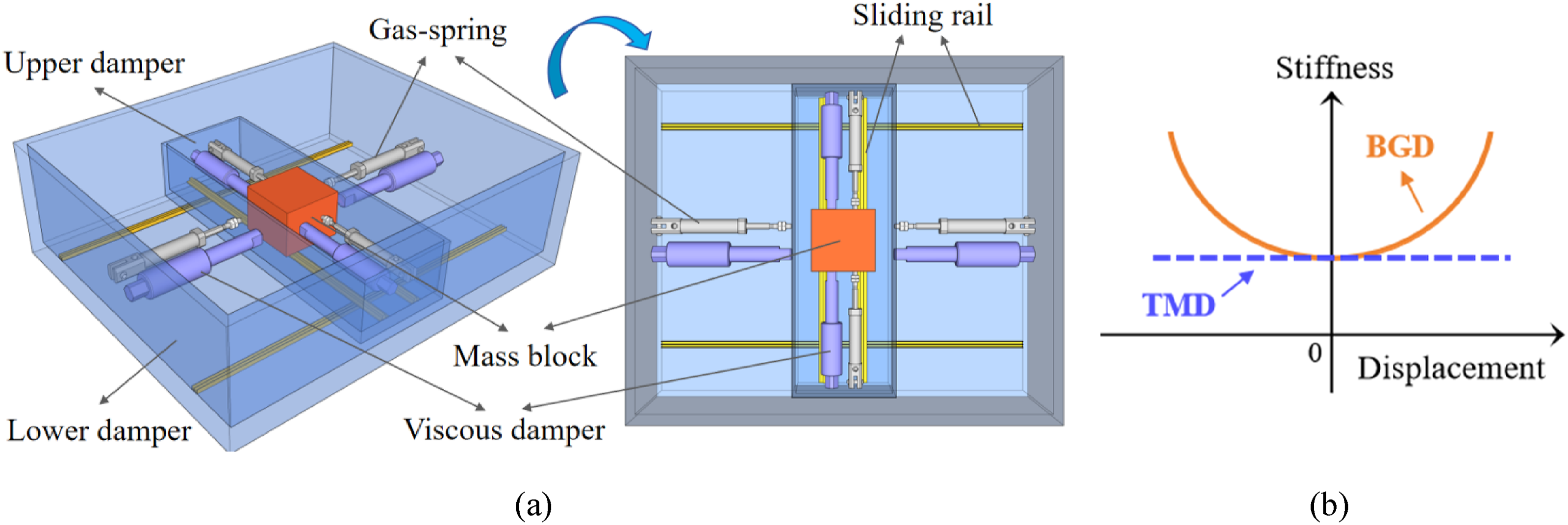
Parametric preliminary design method
The initial tuning stiffness coefficient, damping coefficient, piston radius, working length and initial gas pressure are the BGD’s key configuration parameters. Firstly, the initial tuning stiffness coefficient





Damper design suitable for LTTS
Configuration parameters for both dampers.

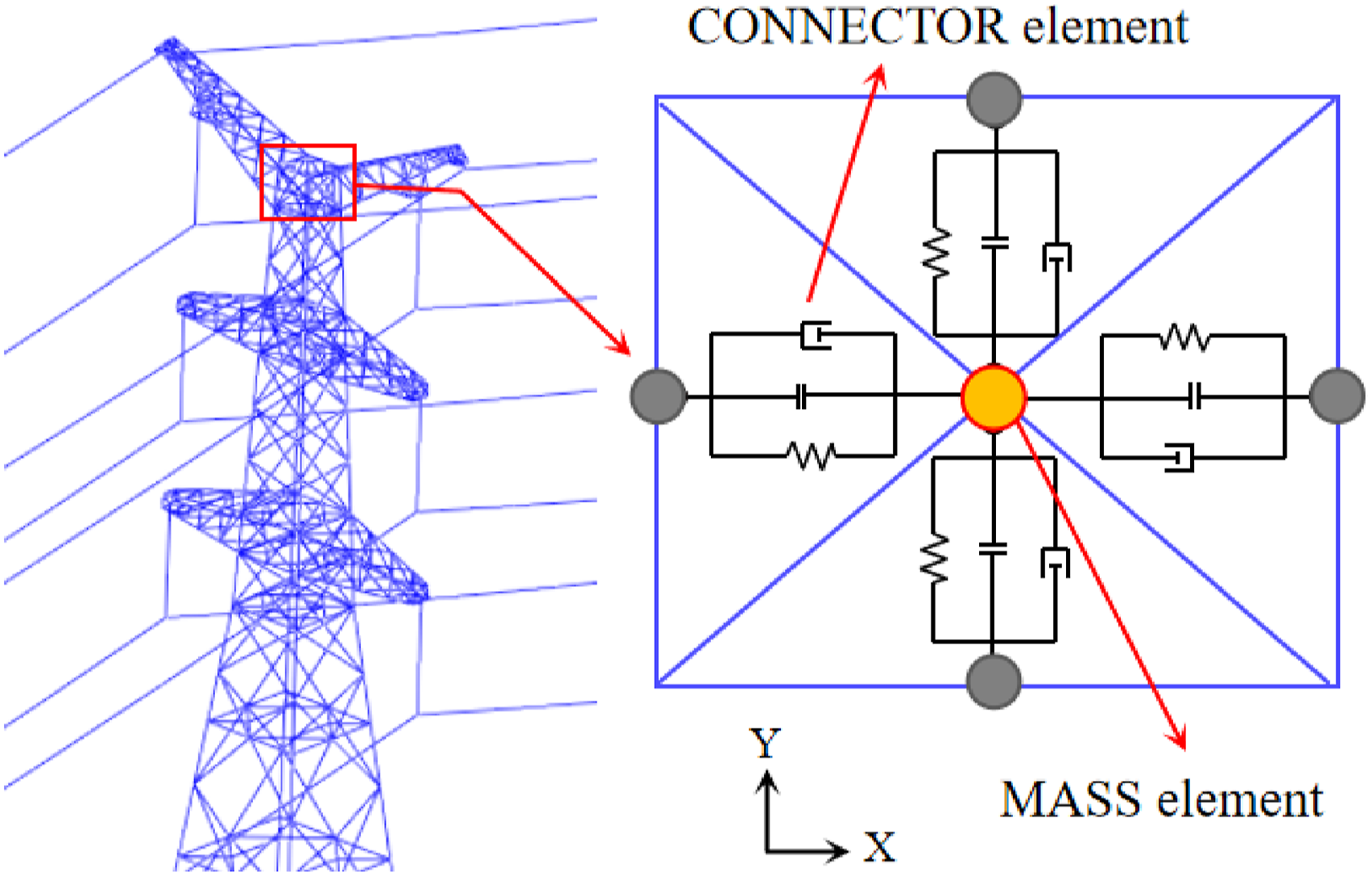
Numerical modeling approach of BGD.
Wind load generation
In actual engineering, wind loads on structures exhibit randomness (Chang et al., 2018). Specifically, wind direction follows the local wind rose pattern, and the wind speed follows the smaller probability of occurrence for larger ones and the larger probability of occurrence for smaller ones. Large winds cause more structural fatigue damage over the same period compared to light winds. Therefore, when analyzing structural fatigue damage, the probability of different wind conditions must be considered, and actual damage under each condition should be evaluated. This study analyzes 50 years of meteorological data from a weather station near the large-span transmission line project site to determine the combined probability distribution of wind direction and speed. Based on this, wind loads acting on the transmission lines are generated. Details on wind direction and speed analysis are available in literature (Rong et al., 2024), and will not be repeated here.
Using the KAIMAL spectrum, wind loads on the towers and lines are simulated with a linear filtering method and calculated using equations (6)–(9) (Liu et al., 2024), respectively. Here,
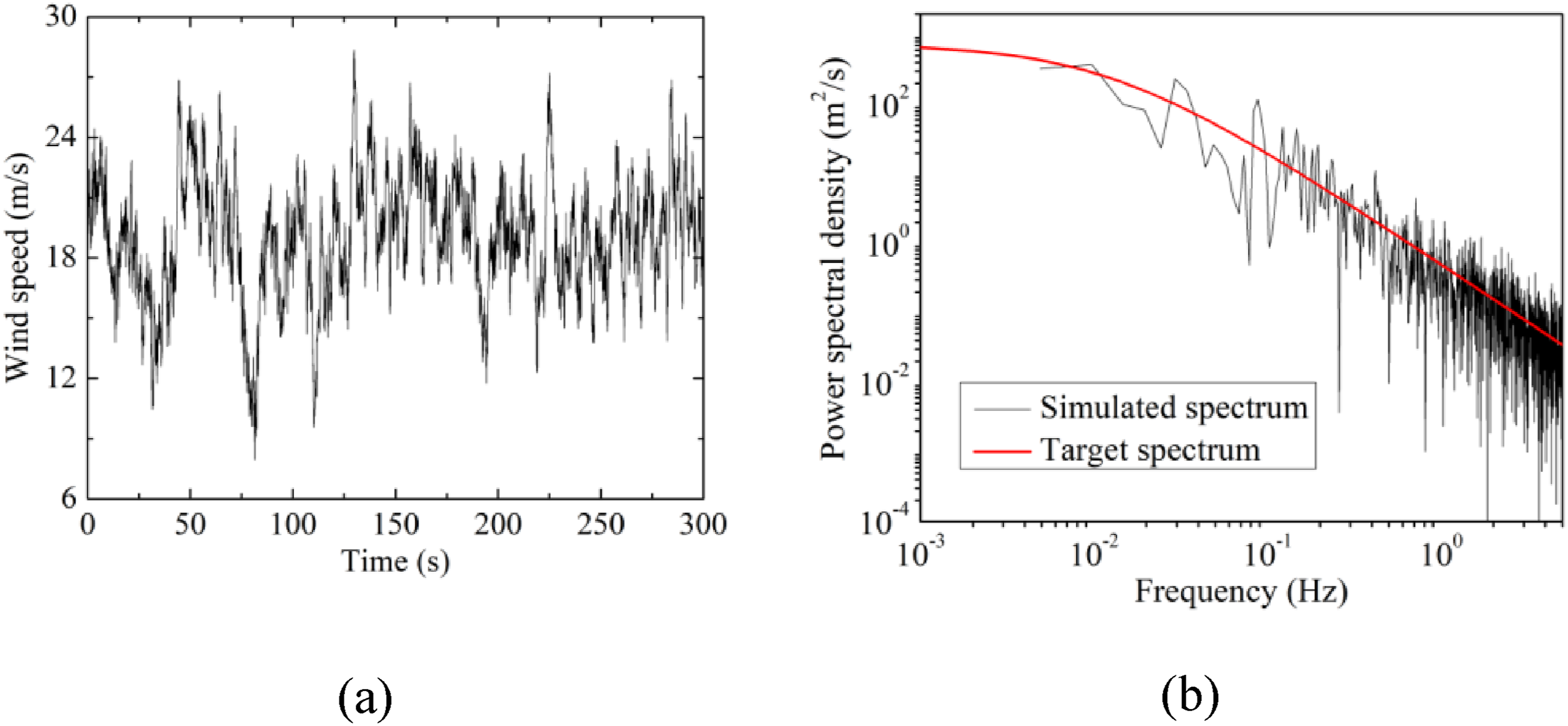
For example, with a basic wind speed of 15 m/s and surface roughness type B, the wind speed time history curve at a height of 32 m for the tangent tower T2 is shown in Figure 6, along with a comparison between the target spectrum and the simulated spectrum. The good overall fit indicates the reliability of the simulation results for subsequent analysis. Wind speed simulation results for tangent tower T2 at 32 m height. (a) Time history curve and (b) spectrum.



Control effectiveness analysis of BGD
This section uses the top displacement response of the LTTS as an evaluation metric to assess the vibration reduction performance of BGD, and the performance advantages of BGD are highlighted by comparing the TMD results. It is proven that the damping frequency band of the BGD is wider compared with the TMD through the analysis of the frequency ratio parameters, and the analysis results of the initial gas pressure parameters are used to elucidate the influence law of the frequency ratios on its vibration reduction performance, finally, the pressure-reduced design concept of the BGD is introduced. Unless otherwise specified, data analyses are based on tangent tower T2 (the tower with the damper installed), using a basic wind speed of 21 m/s and a wind attack angle of 45°, with frequency ratio set to 1.0 and initial gas pressures of 8847447 Pa (X direction) and 8880050 Pa (Y direction). To quantify the damper’s control effectiveness, the peak vibration reduction ratio is defined and expressed by equation (10).
Analysis of control effectiveness
Control effectiveness of two dampers in X and Y directions.

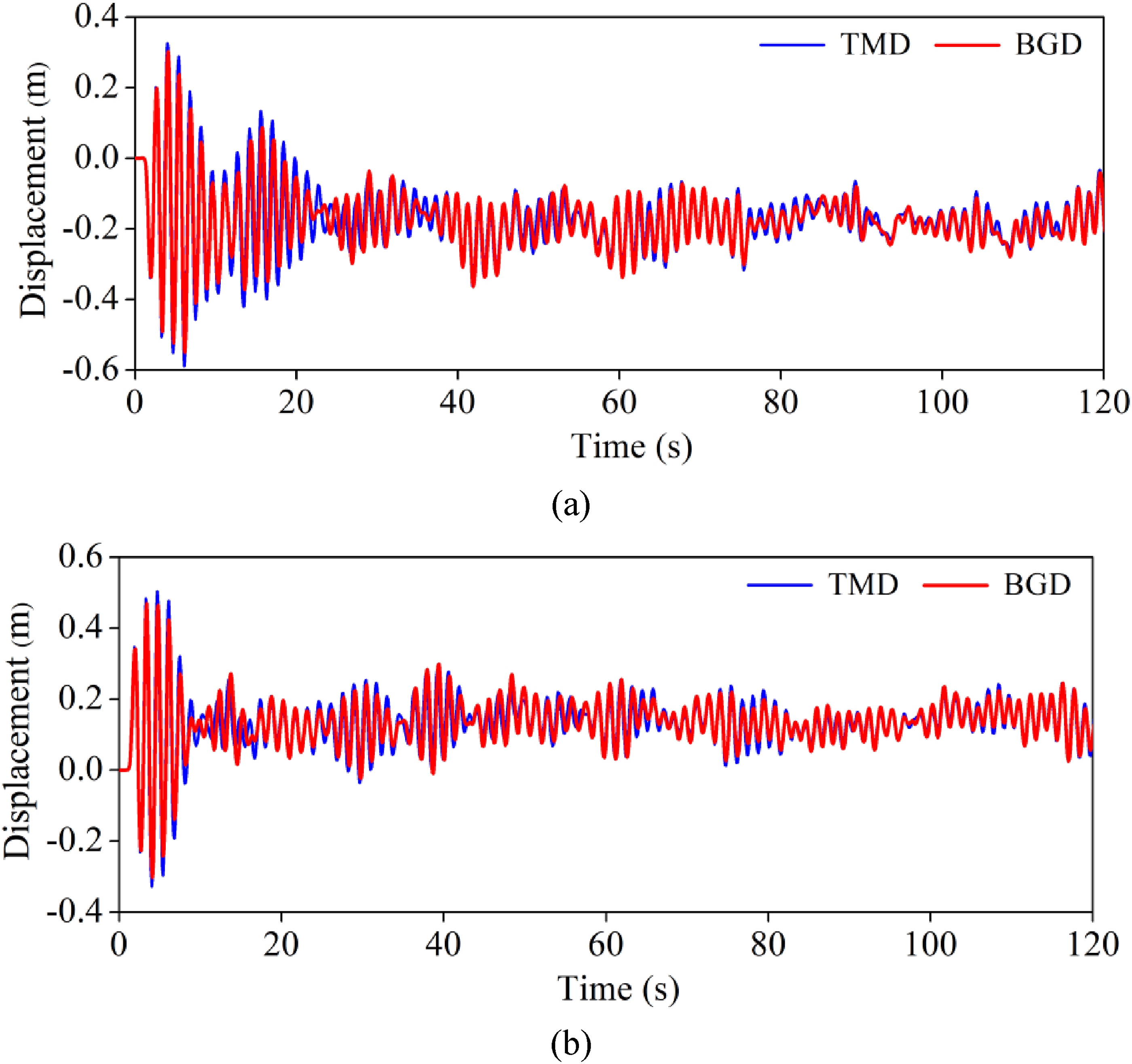
To visually demonstrate the control effectiveness of both dampers, Figure 7 compares the top displacement time history curves of T2 (W/O control, TMD control, and BGD control). The uncontrolled structure’s response curve fully envelops the controlled structure’s curve, indicating a significant mitigation in structural displacement response after attaching the dampers. The response curves for TMD and BGD show that the peak response of the red curve representing BGD is relatively smaller. Additionally, the displacement response time history curves of the mass blocks for TMD and BGD under the same conditions are shown in Figure 8. The results reveal that BGD has a shorter working stroke, reducing the working stroke by 6.62% and 6.83% in the X and Y directions, compared to TMD. This demonstrates that BGD not only provides similar wind-induced vibration control as TMD but also works with a shorter stroke. Comparison of top displacement responses of T2. (a) X; (b) Y. Comparison of working strokes of TMD and BGD. (a) X; (b) Y.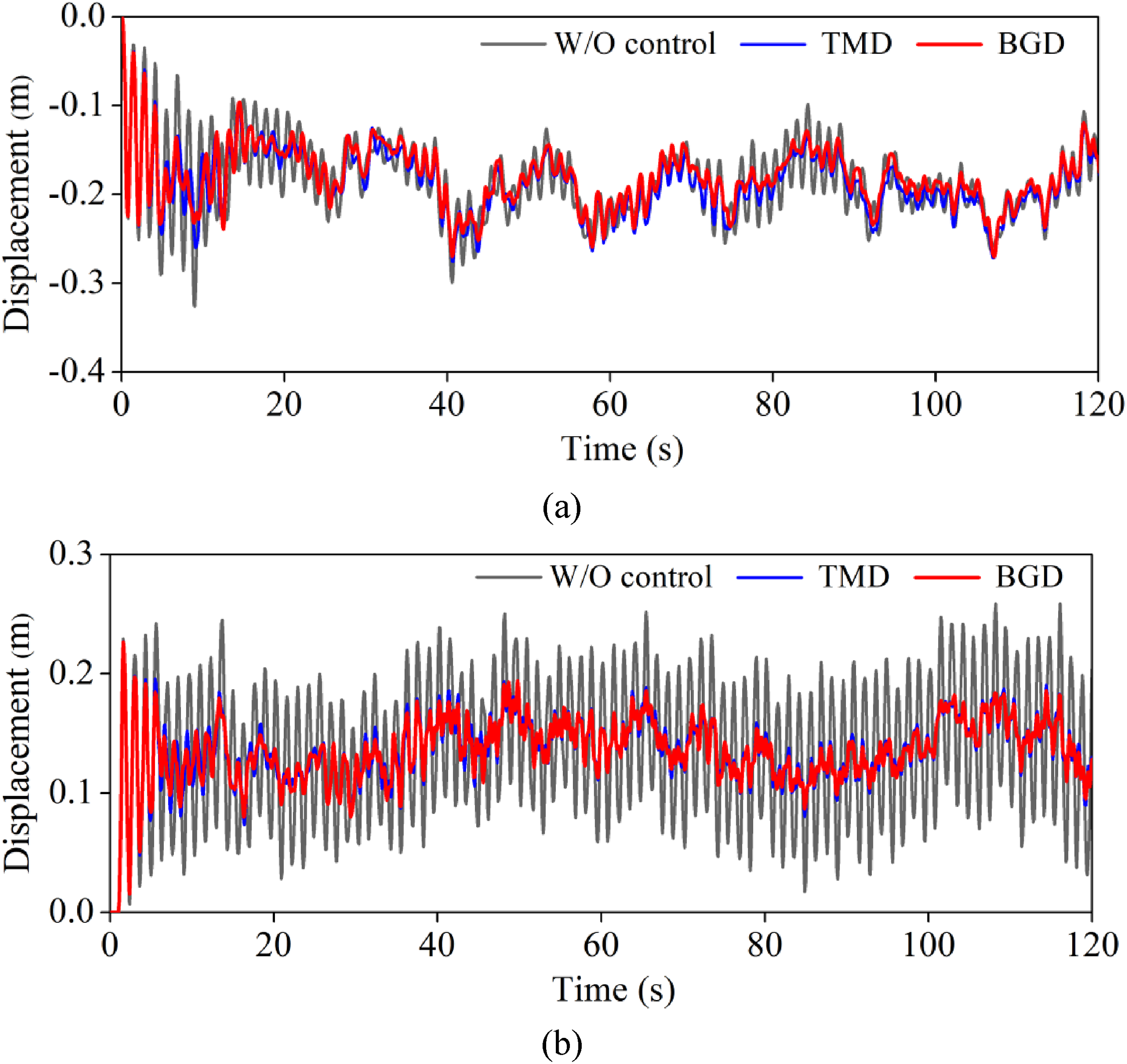
Influence of frequency ratio
A frequency ratio of 1.0 represents the optimal tuning state, providing the theoretically best control effectiveness. Frequency ratio analysis assesses the control performance of the detuning dampers. This section considers five frequency ratio conditions: 0.8, 0.9, 1.0, 1.1, and 1.2.
Figure 9 presents the trend of displacement reduction ratios in two directions as the frequency ratio changes. Both dampers’ control effectiveness initially increase and then decrease with the frequency ratio. The optimal frequency ratio for TMD is 1.0, consistent with linear TMD design principles, whereas BGD’s optimal frequency ratio is between 0.9 and 1.0. Notably, when the frequency ratio is below 1.0, BGD outperforms TMD in vibration reduction effectiveness. However, when the frequency ratio exceeds 1.0, BGD’s reduction ratio significantly decreases and can be lower than TMD’s. Trend of displacement reduction ratios of dampers as the frequency ratio changes. (a) X; (b) Y.
This phenomenon occurs because BGD is a nonlinear damper (equilibrium state: Relationship between the initial state and the working state of the BGD.
Influence of initial gas pressure
The initial gas pressure determines the BGD’s initial tuning stiffness. According to the preliminary design method, the BGD’s working stiffness
To address this issue, the author proposes reducing the initial gas pressure to decrease the initial tuning stiffness (potentially making it less than that of TMD), reducing the variation rate of the BGD’s stiffness, this makes BGD more effective in handling varying intensity random excitations, and the parameter optimal method is named as the pressure-reduced design method. Figure 11 compares the stiffness-displacement performance curves of the damper before and after pressure reduction. Comparison of stiffness-displacement performance curves of BGDs before and after pressure-reduced design.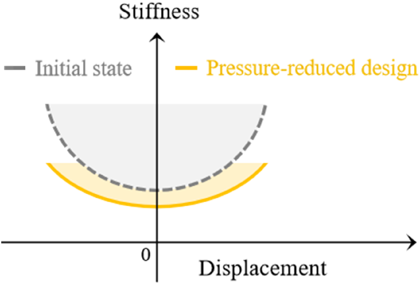
This section analyzes initial gas pressure parameters by setting five conditions: original pressure, and reductions of 5%, 10%, 15%, and 20%. Figure 12 illustrates the trend of displacement reduction ratios in two directions as initial gas pressure changes. Although the Y direction’s reduction ratio curve is not significant, the X direction shows an initial increase and then a decrease in reduction ratios as the pressure reduction percentage increases. Overall, a 10% pressure reduction provides the highest benefit for BGD. Therefore, a 10% reduction in initial gas pressure is used for subsequent fatigue performance analysis of the controlled LTTS. Trend of displacement reduction ratios as initial gas pressure changes. (a) X; (b) Y.
Based on the parameter analysis of frequency ratio and initial gas pressure, the design process of the BGD is further optimized to reflect the concept of pressure-reduced design, and the specific design process is shown in Figure 13. Parametric pressure-reduced design process of BGD.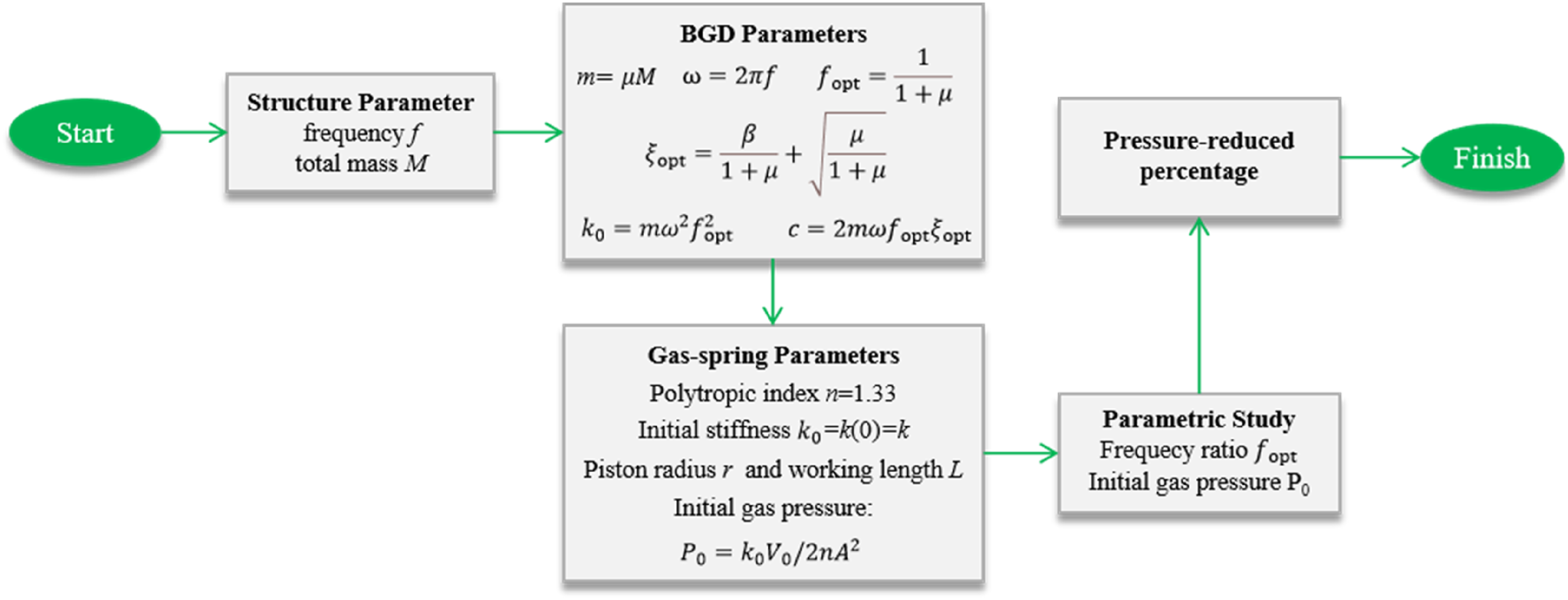
Fatigue life analysis of BGD-controlled structure
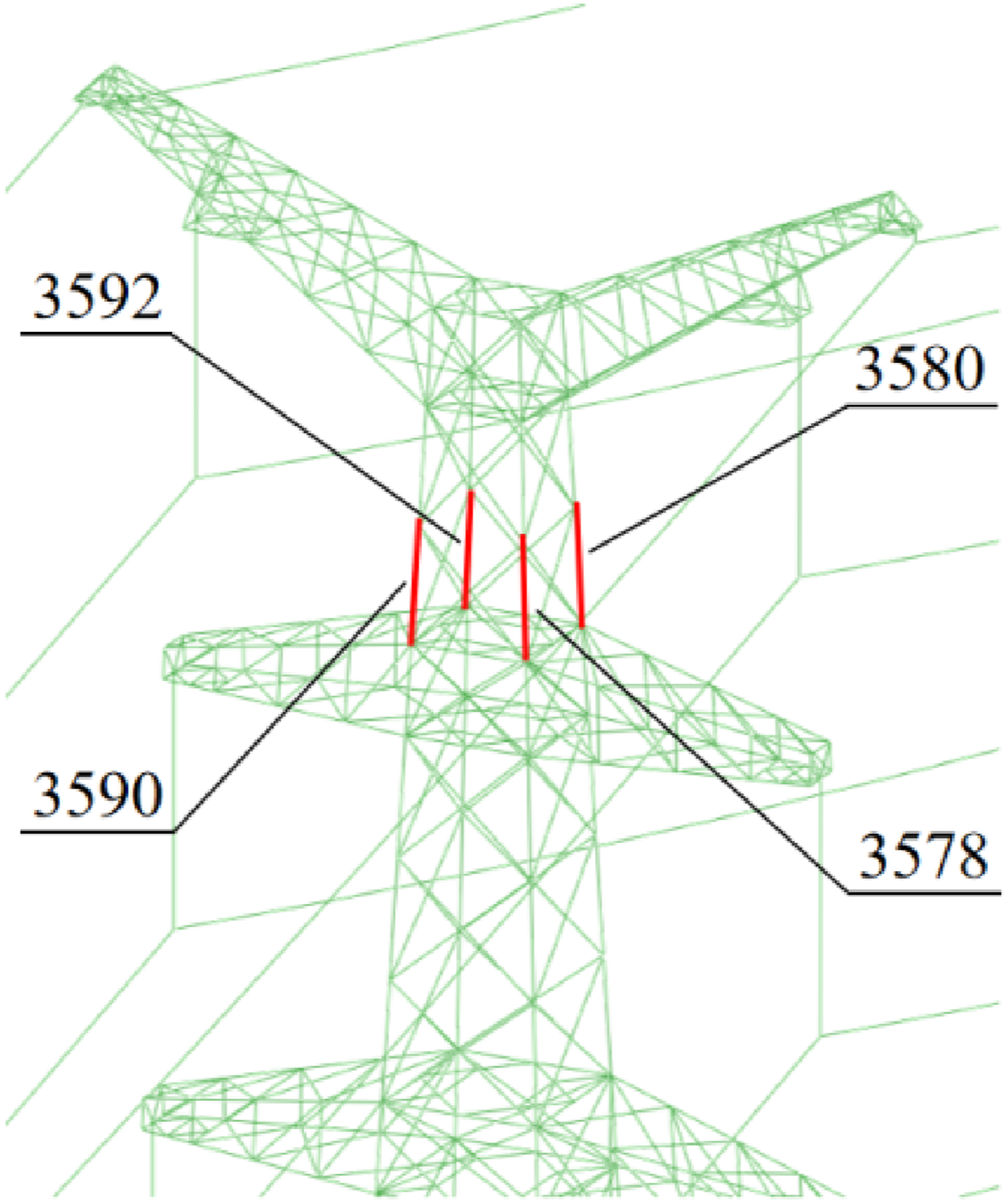
This section focuses on the wind-induced vibration fatigue life analysis of controlled LTTS. The multivariate fatigue damage analysis method proposed in Reference Rong et al. (2024) is employed to investigate the sensitive members’ fatigue damage in the controlled LTTS, the corresponding fatigue damage analysis process is presented in Figure 14. Reference Rong et al. (2024) identifies sensitive members for structural fatigue performance analysis, from which members located in the main components (No. 3592, 3590, 3580, and 3578) are selected for controlled structure fatigue life analysis. The location of the sensitive members is presented in Figure 15. Fatigue damage analysis process of LTTS’s members. Location of sensitive members.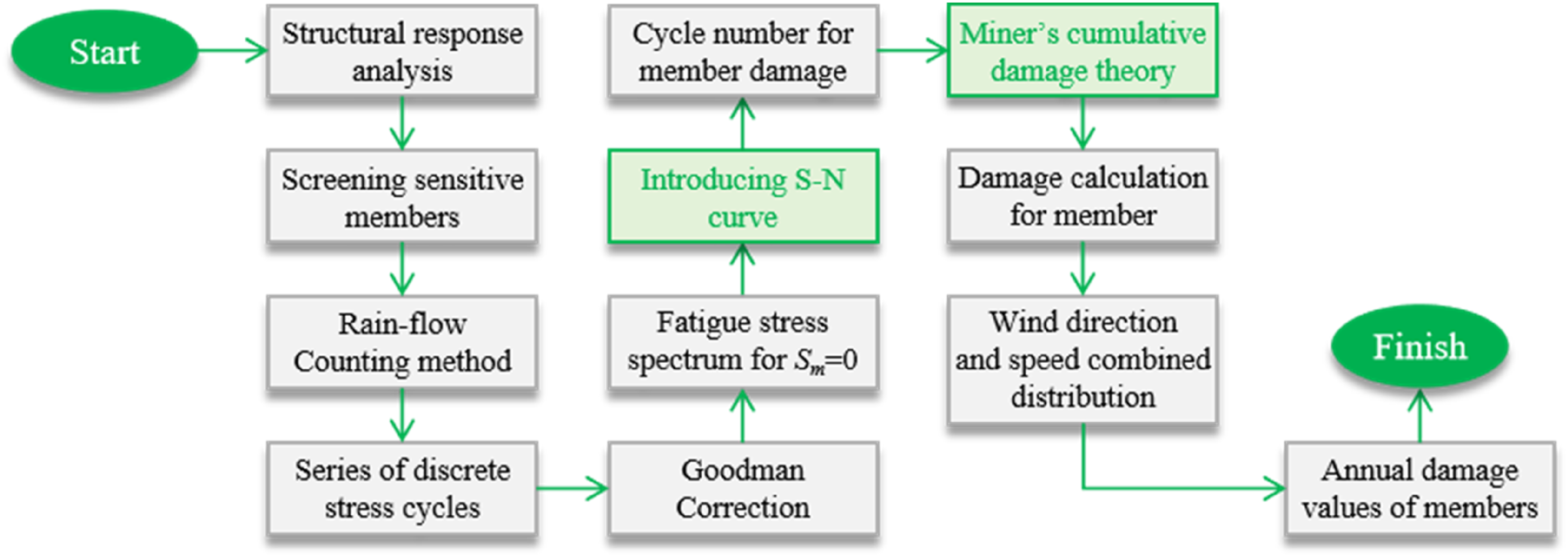
The cumulative fatigue damage values of each sensitive member under the cyclic loading with a single action time of 


Fatigue damage analysis
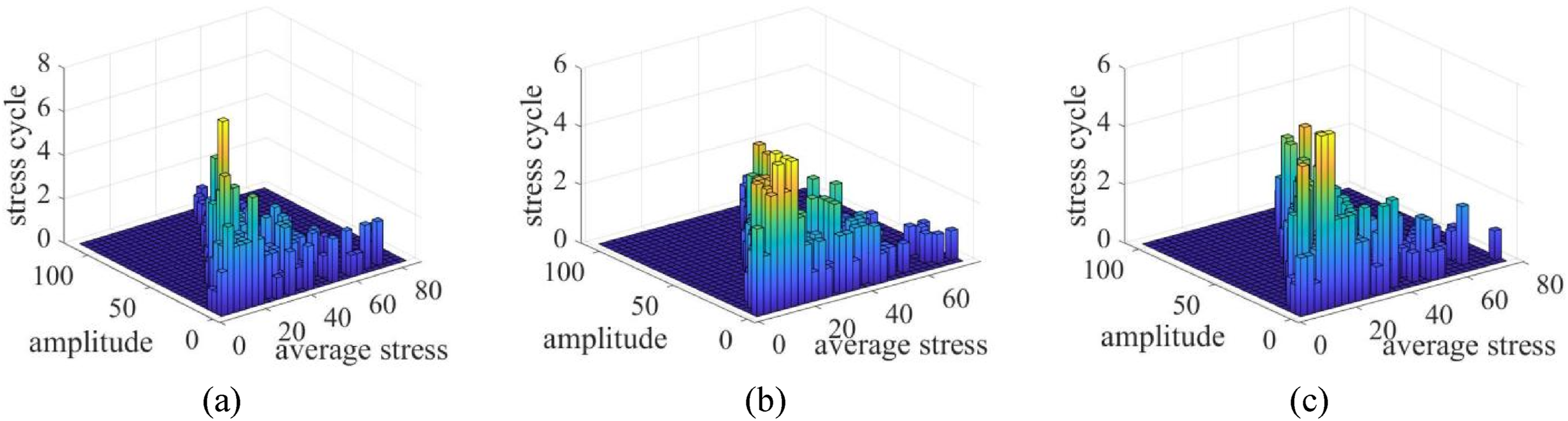
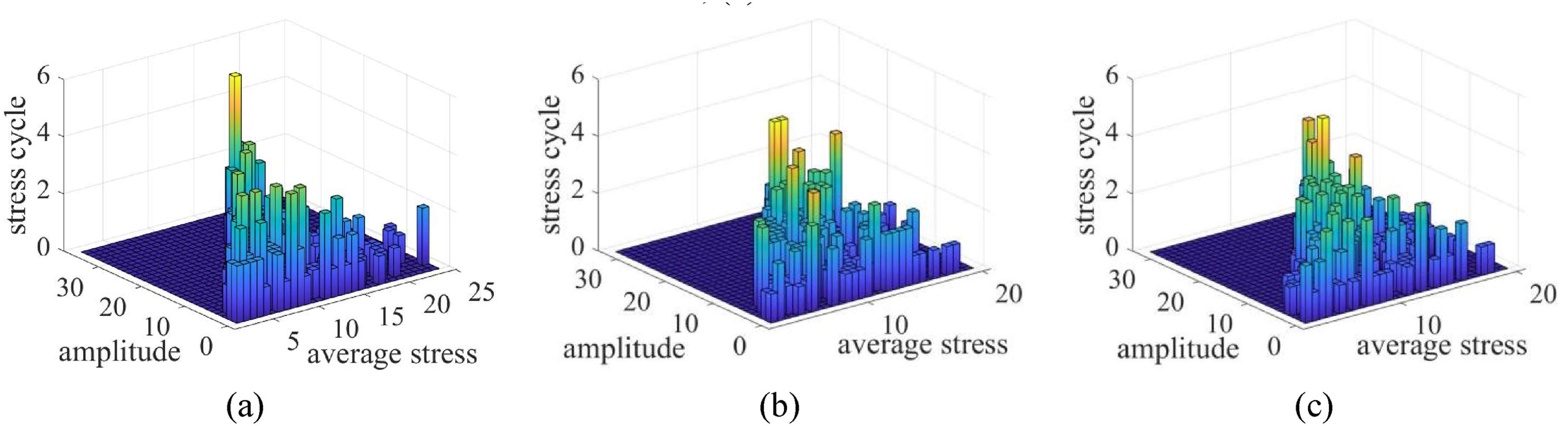
This subsection primarily analyzes three wind conditions at a basic wind speed of 21 m/s with wind attack angles of 0°, 45°, and 90°. Using member 3592 as an example, the stress time history curves of LTTS with and without control are compared in Figure 16. Both dampers effectively reduce the stress response of sensitive members, particularly at a 90° wind attack angle, demonstrating that dampers can significantly mitigate fatigue damage. Figures 17–19 illustrate the stress cycle distribution of the members processed by the rainflow counting method. It is observed that TMD and BGD control significantly reduce the high mean stress amplitude, further confirming the effectiveness of dampers in reducing fatigue damage. Comparison of stress time history curves of sensitive member 3592 with and without control. (a) wind attack angle 0°, (b) 45°, and (c) 90°. Stress cycle distribution of 3592 under wind attack angle 0° (MPa). (a) W/O control; (b) TMD control; (c) BGD control. Stress cycle distribution of 3592 under wind attack angle 45° (MPa). (a) W/O control; (b) TMD control; (c) BGD control. Stress cycle distribution of 3592 under wind attack angle 90° (MPa). (a) W/O control; (b) TMD control; (c) BGD control.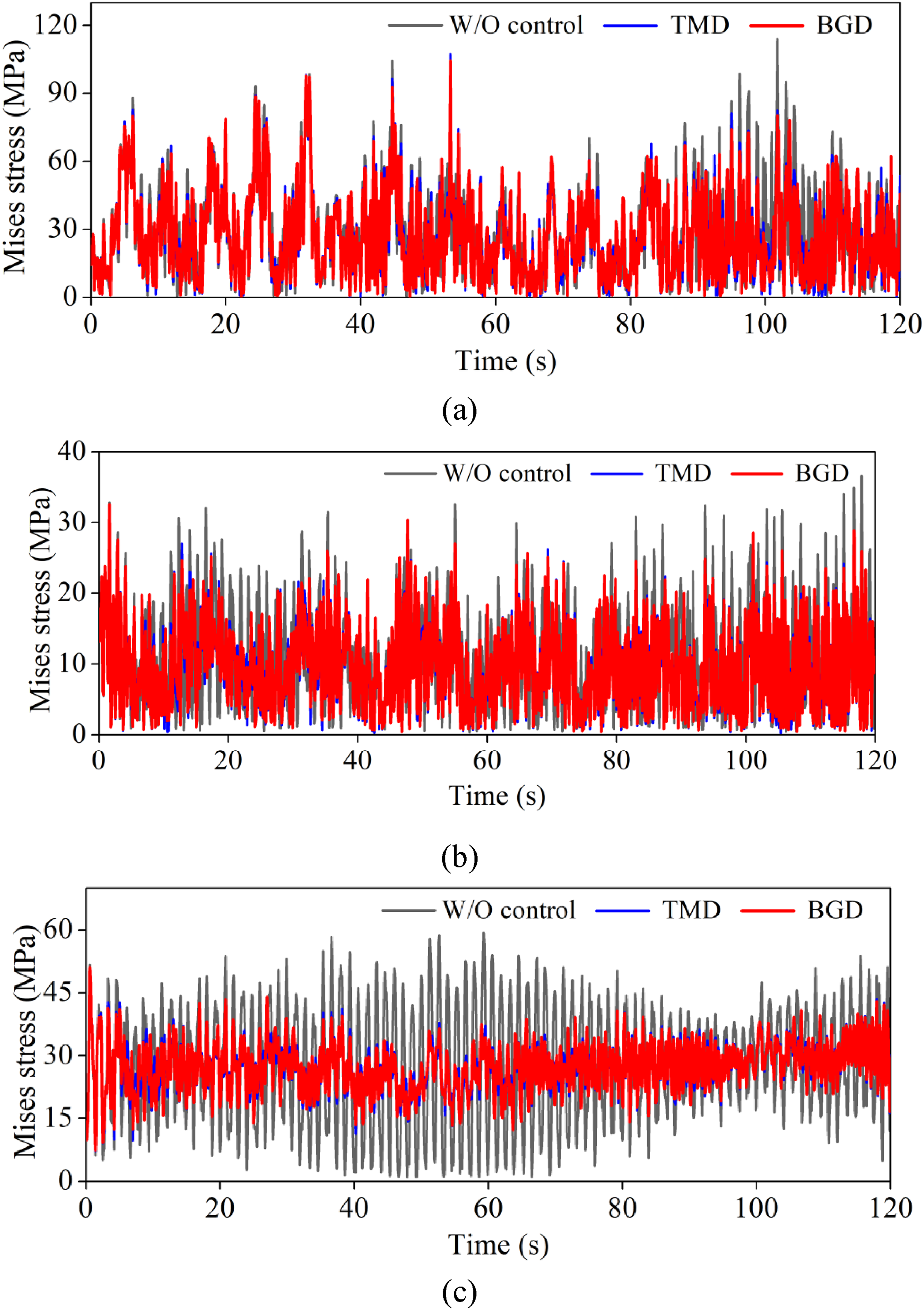

Life-prolonging analysis
To quantify the life-prolonging effectiveness of BGD on the LTTS, a life-prolonging ratio is defined by equation (14). A higher life-prolonging ratio indicates a longer fatigue life, demonstrating the superior effectiveness of the damper. Besides, the fatigue life analysis of the linear TMD-controlled structure is conducted to highlight the superiority of the nonlinear BGD in enhancing the fatigue resistance and extending the structure’s fatigue life.
Members’ (3592, 3590, 3580, and 3578) fatigue life under uncontrolled, TMD-controlled, and BGD-controlled conditions is shown in Figure 20. Radar chart comparisons indicate that the members’ fatigue life is significantly longer under TMD and BGD control than in the uncontrolled state. For example, the fatigue life of member 3592 is 126.16 years without control, 221.39 years with TMD control (a 75.5% life-prolonging ratio), and 297.40 years with BGD control (a 135.7% life-prolonging ratio). Overall, the life-prolonging ratio for TMD exceeds 60%, while BGD exceeds 80%, indicating that nonlinear BGD is more effective than linear TMD. Comparison of fatigue life of structures with and without control.
The superior performance of nonlinear BGD is attributed to its better control of structural displacement response compared to linear TMD, as displacement response is a critical factor in mitigating the members’ stress amplitude. Consequently, under identical wind conditions, smaller structural displacement response results in less accumulated damage to the members, thereby extending the structure’s fatigue life.
Conclusions
This study proposes a bidirectional gas-spring damper (BGD) to mitigate wind-induced vibrations in LTTS, enhancing fatigue resistance and extending structural fatigue life. The working principle and parametric preliminary design method for BGD are detailed. Relying on the actual project, a refined numerical model of the LTTS is established using ABAQUS, and the wind load as an input is generated. The control effectiveness analysis of TMD and BGD on wind-induced vibration and its key parameter analysis are carried out. The effectiveness of BGD for reducing structural fatigue damage and extending the structural fatigue life is evaluated and discussed. The systematic findings are as follows: (1) Compared to TMD, BGD offers similar vibration reduction ratio for wind-induced displacement responses, with smaller working strokes and a wider damping frequency band. The optimal frequency ratio for BGD is recommended between 0.9 and 1.0, where performance is superior to TMD when below 1.0, but rapidly declines above 1.0. (2) BGD achieves maximum vibration reduction benefits at an initial gas pressure of 0.9 (3) BGD significantly reduces stress responses and high mean stress amplitudes in sensitive members of the LTTS, thereby enhancing fatigue resistance and extending structural fatigue life. For instance, the member’s (3592) fatigue life is extended by 75.5% with TMD control, while BGD achieves a life-prolonging ratio of 135.7%.
Footnotes

Author contributions
Kunjie Rong: Investigation, Supervision, Writing - original draft; Junrong Gong: Software, Data curation; Li Tian: Conceptualization, Writing -review & editing; Jingyu Luo: Resources, Writing - review & editing; Na Li: Investigation, Writing -review & editing. All authors have read and agreed to the published version of the manuscript.
Funding
The authors disclosed receipt of the following financial support for the research, authorship, and/or publication of this article: This work was supported by the Taishan Scholars Program.
Declaration of conflicting interest
The authors declared no potential conflicts of interest with respect to the research, authorship, and/or publication of this article.
Data Availability Statement
Data will be made available on request.