
Abstract
Steel-concrete composite bridge decks (CBDs) have been widely used in practical bridge structures. In recent years, a novel assembled CBD comprising of sectional steels and perfobond rib (PBL) shear connectors was recently developed for eliminating the on-site welding requirements and reducing the steel consumption. By using ultra-high toughness cementitious composite (UHTCC) as the surface layer, the durability of the assembled CBDs could be further improved. In this paper, analytical and numerical investigations on the flexural behavior and ultimate capacity prediction of the assembled steel-UHTCC CBDs are performed. Firstly, a theoretical model considering various degrees of shear connection and the shear-slip effect of PBL shear connectors was developed to predict the ultimate flexural capacities of assembled steel-UHTCC CBDs with PBL shear connectors under both sagging and hogging moments. Subsequently, finite element (FE) models of assembled steel-UHTCC CBDs with various numbers of PBL shear connectors and profile steel parts in shapes of T, Z, B and H were established using ABAQUS, and validated against existing experimental results. Finally, the proposed theoretical model was validated using FE simulation results, with deviations not exceeding 10% and most of them are within 5%, demonstrating the accuracy of the proposed theoretical model. This paper provides a practical method to calculate flexural capacity and optimize PBL shear connector layouts, significantly improving the cost efficiency when designing CBD structure.
Keywords
Introduction
In recent decades, the increasing demands of transportation have necessitated the rapid development of long-span bridges, thereby imposing significant challenges on bridge engineering. For their superior sectional stiffness compared to orthotropic steel bridge decks (OSBD), steel-concrete composite bridge deck (CBD) structures have garnered attention, which mitigate fatigue in steel components (Qin et al., 2022; Zhu et al., 2020). But the traditional CBDs involve large amount of steel plates and shear connectors welding, which is costly, complex, and difficult to ensure quality. The assembled CBDs offer a solution to the problem.
However, the implementation of assembled steel-concrete CBDs in long-span bridge decks encounter several challenges. The high weight and low tensile strength of conventional concrete often result in lower crack resistance and necessitate a thicker cover layer of over 120 mm (Su et al., 2018). Additionally, the ultimate capacity of CBDs is significantly influenced by the strength of shear connection between steel and concrete (Walter et al., 2007), often resulting in the extensive use of shear studs. The proliferation of studs increases steel consumption and introduces additional fatigue details at the welding area. To address cracking issues, the use of new materials in pavement layers has been explored. Shao et al. introduced ultra-high-performance concrete (UHPC) in the construction of steel-UHPC CBD structures. (Feng et al., 2021; Luo et al., 2019; Shao et al., 2023). The exceptional strength and ductility of UHPC can significantly reduce the thickness of pavement layers to about 50 mm. However, there are still risks of cracking in the hogging moment regions within steel-UHPC CBDs (Nasrin and Ibrahim, 2021; Shao et al., 2018). To reduce steel consumption and welding areas, researches have focused on innovative shear connectors, particularly the Perfobond rib (PBL) (Karam et al., 2020; Sun et al., 2023). PBL connectors are composed of perforating rebars and concrete tenons cast through rib perforations, noted for their high ductility, load-bearing capacity, and fatigue resistance when used in composite structures (He et al., 2013; Kim et al., 2011; Li et al., 2018; Liu et al., 2013). However, the application of PBL in traditional steel-concrete CBDs presents some challenges. The PBL ribs will split the concrete initially, increasing the risk of cracking during service. This indicates a compatibility issue between PBL connectors and concrete.
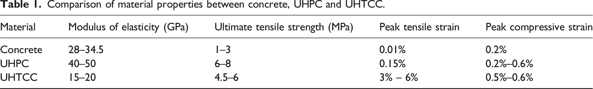
Comparison of material properties between concrete, UHPC and UHTCC.
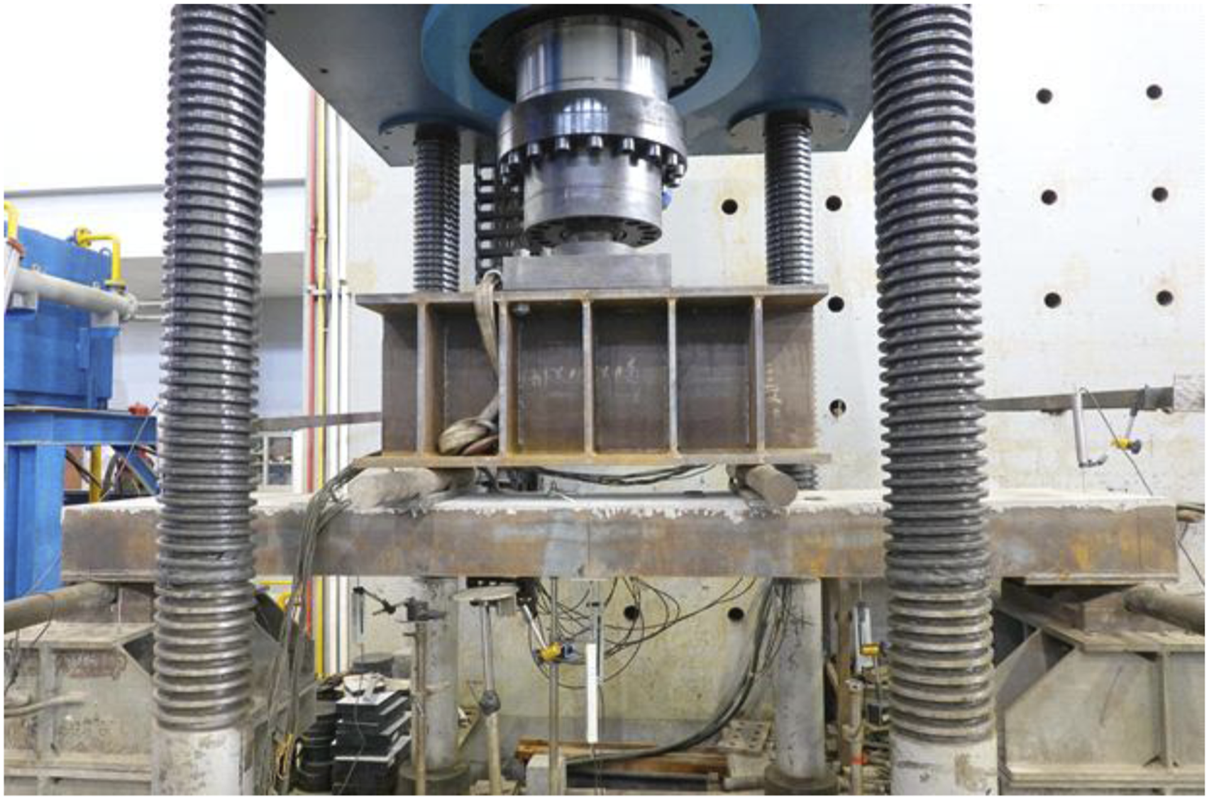
To facilitate easier assembly and enhance mechanical properties (Chen et al., 2024) proposed novel assembled CBDs incorporating UHTCC and specially designed profiled steel parts. The cold-formed duplicate profiled steel parts in various shapes (T, Z, B, and H) are pre-drilled with PBL holes and then welded together, reducing the amount of steel plates welding. By threading the reinforced bars through the reserved holes, the PBL connectors can be formed above the steel plate, as shown in Figure 1. Four-point bending tests were conducted on four types of proposed assembled steel-UHTCC CBDs to study the flexural performance of assembled steel-UHTCC CBDs under sagging moment, as illustrated in Figure 2. Proposed assembled steel-UHTCC CBD. Schematic diagram of experimental instrument.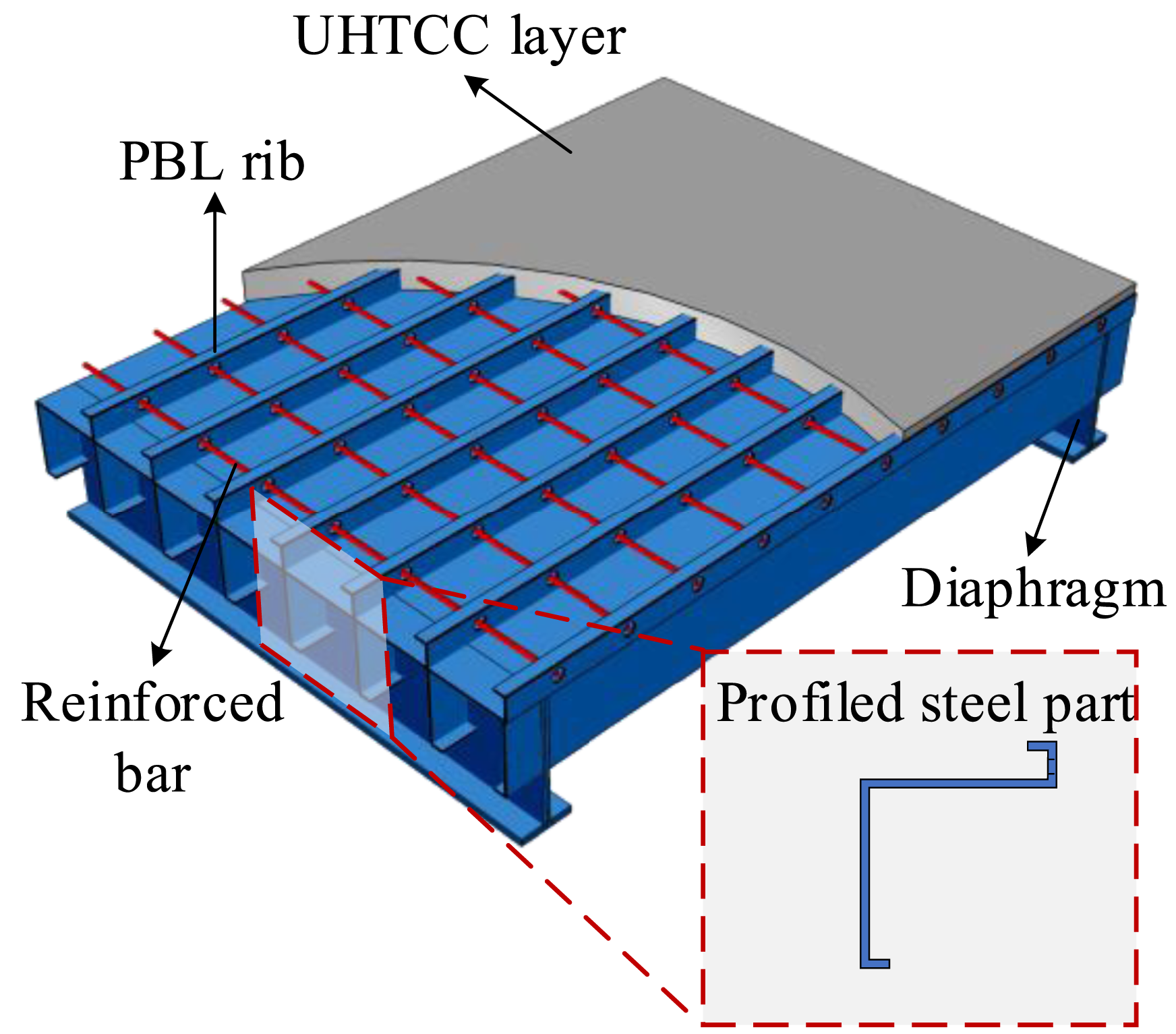
The research indicated that UHTCC, due to its excellent crack resistance, has better compatibility with PBL connectors compared to other types of concrete, and can effectively reduce cracking caused by PBL separation. The combination of UHTCC and PBL in assembled CBDs can achieve better engineering convenience, higher load capacity and durability (Chen et al., 2024). Profit by their excellent performance, the assembled steel-UHTCC CBDs have great application value in engineering. The research on flexural performance of the assembled CBDs is of great significance for the design and application of this new type of CBD.
Existing research on the assembled steel-UHTCC CBDs primarily employs over-dense PBL shear connectors to achieve complete shear connections. A reduction in PBL shear connectors could enhance construction efficiency and mitigate fatigue risks caused by excessive welding, but limited attention has been given to the flexural behavior of steel-UHTCC CBDs under partial shear connections. Consequently, systematic exploration on how various degrees and shear-slip effect of shear connection influence flexural performance is critical for improving the cost-effective and fatigue-resistant CBD systems.
In this study, a theoretical model is developed to predict the ultimate flexural capacities of assembled steel-UHTCC CBDs with PBL shear connectors under both sagging and hogging moments, considering various degrees of shear connection and the shear-slip effect of PBL shear connectors. Additionally, FE models of novel assembled steel-UHTCC CBDs with various numbers of PBL shear connectors and profile steel parts in shapes of T, Z, B and H are established to validate the accuracy of the theoretical analysis.
Theoretical analysis
Calculation method of shear force
Based on the existing studies, the flexural capacity of assembled steel-UHTCC CBDs is influenced by the interfacial shear connection degree between the UHTCC slab and steel parts. The frictional force between UHTCC and steel parts was neglected in comparison to the shear force provided by PBL connections. Consequently, CBDs were considered as laminated decks when there is no shear connection at the interface.
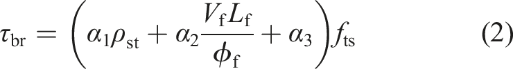
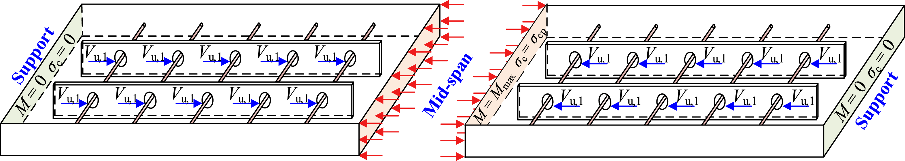
The schematic diagram of the PBL connector is shown in Figure 3. The shear force was simplified as concentrated forces provided by each PBL shear connector. The ultimate shear capacity of an individual PBL shear connector Vu,1 can be expressed as Stress state of UHTCC elements at mid-span section under incomplete shear connection.


The shear-slip behavior of PBL was simplified to an ideal elastoplastic relationship (Kang et al., 2014), characterized as: (1) when the shear force is less than Vu,1, the shear force of the PBL connector is linearly related to its slip deformation; (2) once the shear force reaches Vu,1, the PBL shear connector transitions into a phase of plastic deformation, at which point the shear force ceases to increase with further slip.
Due to the shear-slip effects, the plane section assumption cannot be directly applied to the cross-section of steel-UHTCC composite structures under various degrees of shear connection strength (Pan et al., 2016). Consequently, a theoretical model based on partial interaction theory (Johnson and Lee, 1977; Wang et al., 2019) was proposed, as illustrated in Figure 4. The following assumptions were involved: (1) The plane section assumption is applied to the steel part and UHTCC slab separately. (2) Both the steel and UHTCC are considered to be ideal elastic-plastic materials. (3) Since the UHTCC and steel part are vertically laminated, the curvature and rotation of the them at the same section are equal. Meanwhile, there is slippage along the longitudinal direction of CBD at the interface between UHTCC and steel part. (4) After yielding, cracking in the UHTCC at mid-span leads to a transition in interfacial behavior: plastic deformation of the UHTCC results in a reduction in the growth rate of shear-slip deformation at the steel-UHTCC interface. Thus, Post-yield interfacial shear forces are approximated as the elastic-stage limit value. Analysis of partial interaction on steel-UHTCC CBDs under four-point bending.

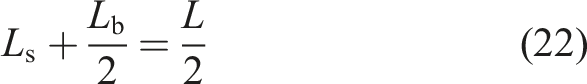
An isolated micro beam element in elevation was shown in Figure 4, with a length of dx. In Figure 4, Ls represents the shear span length, and Lb represents the length of the pure bending region. The slip equation can be expressed as
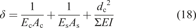
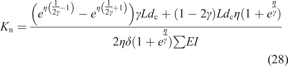
According to equation (5), K can be defined as the longitudinal shear stiffness of the interface, expressed as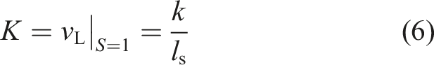

As show in Figure 4, the relationship between N(x) and vL can be expressed as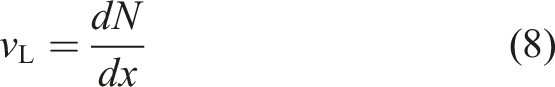
Under the action of external bending moment M, the steel beam is subjected to the combined action of compressive force Ns and bending moment Ms. Concurrently, UHTCC slab is subjected to the combined action of tensile force Nc and bending moment Mc. The axial force Ns and Nc are numerically equal and denoted as N. Based on the equilibrium of bending moments, the relationship between M and N can be expressed as
In the elastic stage, the effect of vertical uplift is negligible, and consequently, the steel part and the UHTCC slab must exhibit the same curvature, denoted as ϕ. The moment-curvature relations can be given by the simple beam theory as

The definition of slip strain is obtained by solving the first derivative of the relative slip S(x) with respect to x. Derived from equations (7) and (8), the slip strain is given by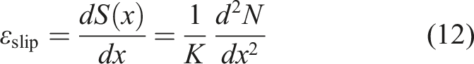
The slip strain ε slip is the sum of the effects of axial force N and moment (Mc + Ms), expressed as
The slip strain caused by axial force N is expressed as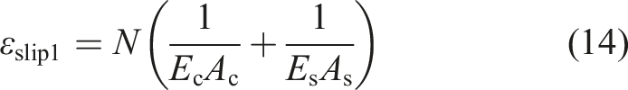
The slip strain caused by bending moment (Mc + Ms) is expressed as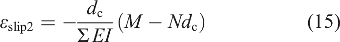

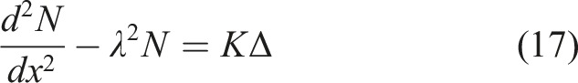

For four-point bending component, the external bending moment of shear span and pure bending section can be expressed as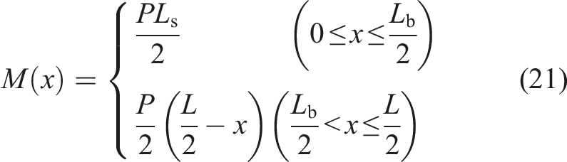
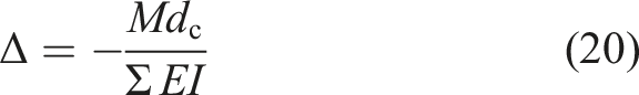
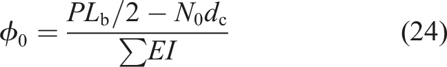
By substituting equation (21) into equation (17), N at shear span and pure bending region can be solved, and the curvature ϕ can be calculated. The detailed solution process has been provided in Appendix A. By substituting x = 0 into the solution, the shear force N0 and curvature ϕ0 at the mid span position can be obtained and expressed as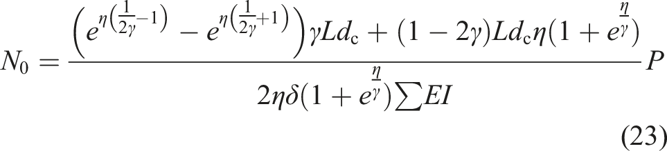


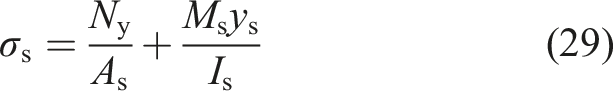
By combining equations (9)–(11), and (27)–(29), the solution for the yield load Py and the shear force Ny can be obtained as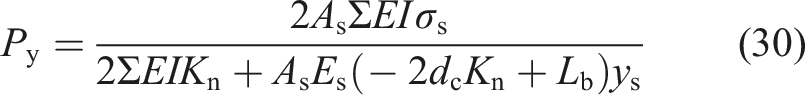

Calculation of ultimate flexural capacity
The Z-shaped profiled steel section has been used as an example for calculation. The detailed dimensions of the components can be found in Figure 5. Steel sections of the other shapes can be calculated by adjusting some of the cross-sectional dimensions shown in Figure 5. Schematic diagram of the dimensions of the cross-section used to calculate the capacity.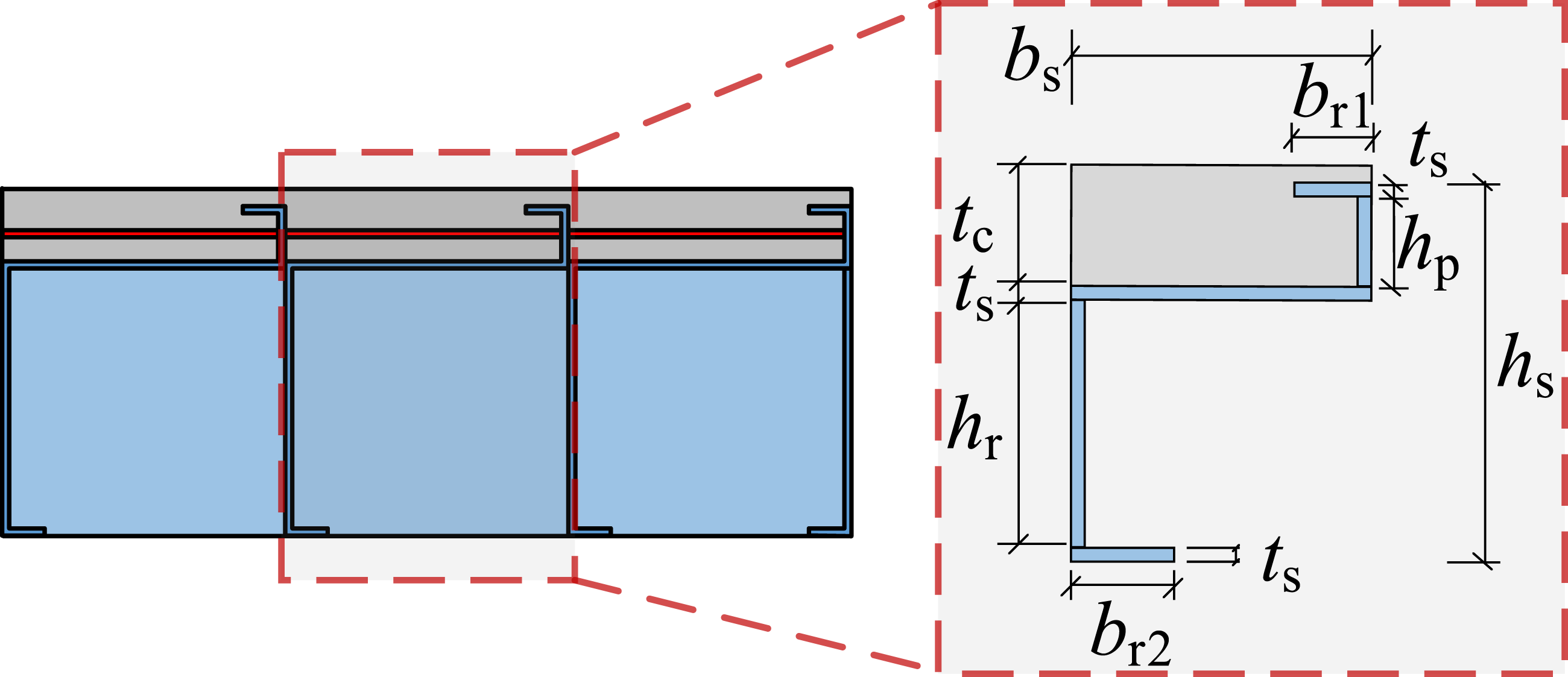
Showing the case of plastic neutral axis below, within, and above the steel plate respectively, Figure 6 illustrates the stress distributions across sections of the steel parts. In Figure 6, Nts and Ncs are the tensile and compressive forces produced by tensile and compressive regions of steel part, respectively; As1 and As2 represent areas of tensile and compression zones of the steel part; h0s represents the distance from the plastic neutral axis of the steel part to its lower edge; ys1 and ys2 respectively are the distances from the centroid of the cross-section in the tensile and compressive regions to the plastic neutral axis of the steel part; Mus is the bending moment contributed by the steel part under the ultimate moment. Schematic diagram for calculating theoretical capacity of steel part with different plastic neutral axis position. (a) Under the steel plate. (b) Within the steel plate. (c) Above the steel plate.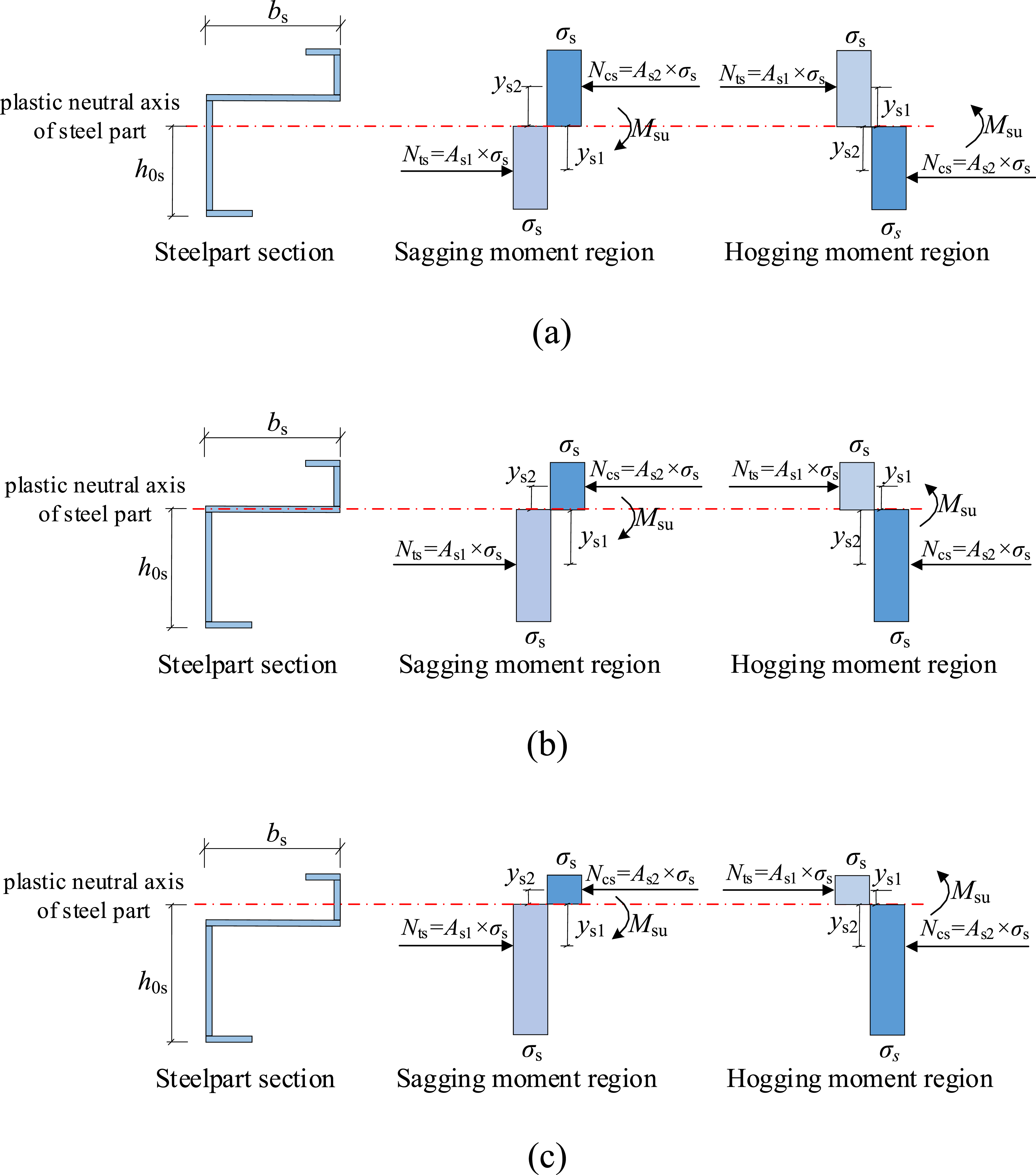
According to the equilibrium condition of axial force, the compressive and tensile stress of steel part should satisfy equation (34) and (35).

The sectional stress distributions of the UHTCC slab are exhibited in Figure 7. Ntc and Ncc are the tensile and compressive force produced by tensile and compressive regions of the UHTCC slab, respectively; Ac1 and Ac2 represent areas of tensile and compression zones of the of the UHTCC slab; h0c represents the distance from the plastic neutral axis of the UHTCC slab to its bottom edge; yc1 and yc2 respectively represent the distances from the centroid of the cross-section in the tensile and compressive regions to the plastic neutral axis of the UHTCC slab; Mu is the bending moment contributed by the UHTCC slab under the ultimate moment. Schematic diagram for calculating theoretical capacity of UHTCC part.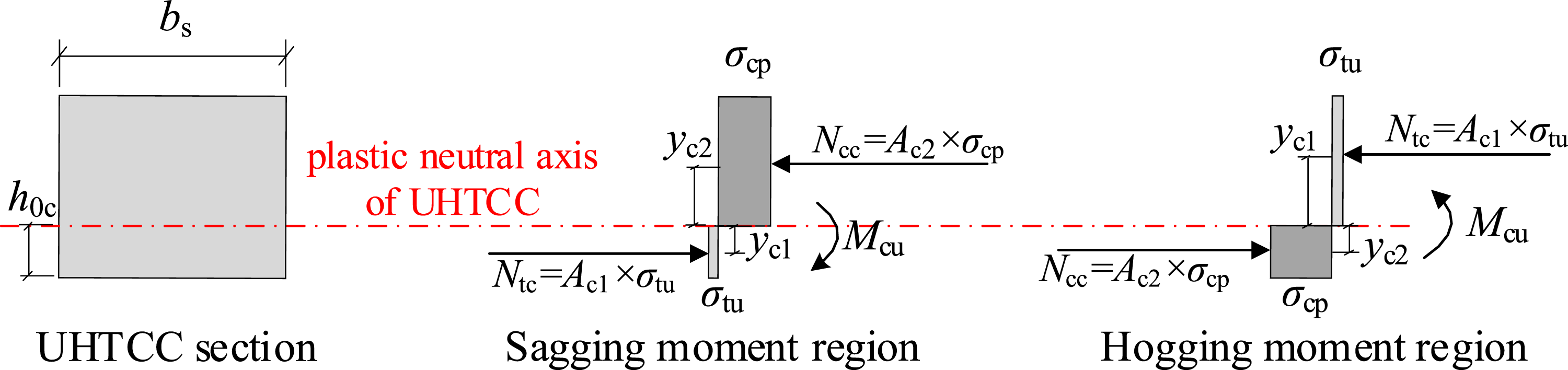
The compressive and tensile stress of the UHTCC slab should satisfy equation (35) and (36).

Similar to the calculation method of steel parts, Mcu can be calculated by combining equations (35) and (36). Since UHTCC is not isotropic material, it has different expressions for Mcu under sagging and hogging moments, detailed in Appendix B. In the end, by substituting equations (32), (34), and (36) into equation (9) , the ultimate moment Mu of assembled CBD can be obtained.
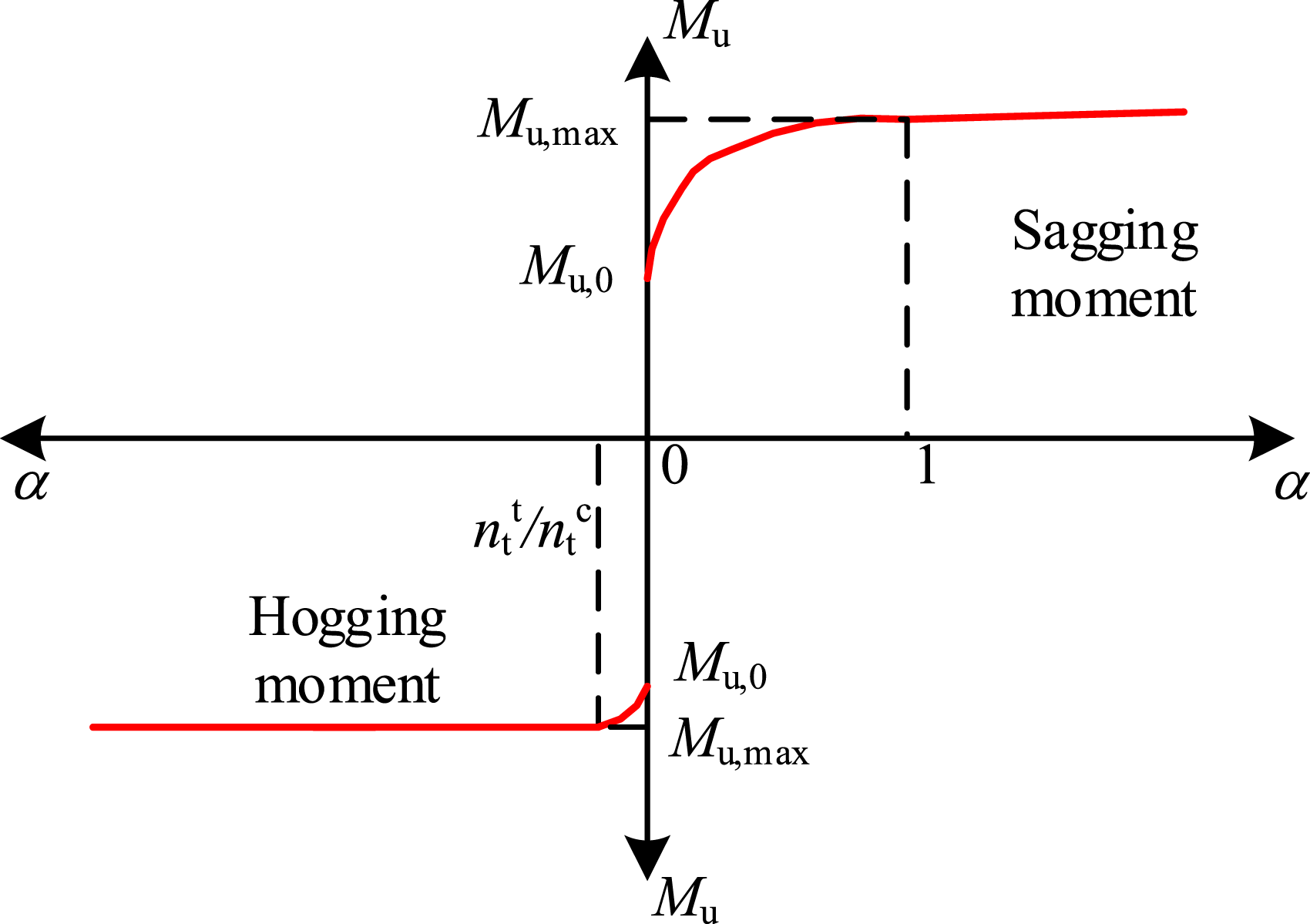
The relationship between the ultimate flexural capacity and the degree of shear connection, as derived from theoretical models, is illustrated in Figure 8. For assembled CBDs of various sizes and shapes, it is challenging to reflect the relationship between the degree of shear connection and ultimate flexural capacity solely through the number of PBL shear connectors. To conveniently evaluate the effectiveness of PBL shear connector numbers in improving the shear connection degree, many existing studies (Chen et al., 2024; Tong et al., 2023) defined the normalized PBL shear connector numbers α as Theoretical curve to predict flexural capacity under sagging and hogging moment.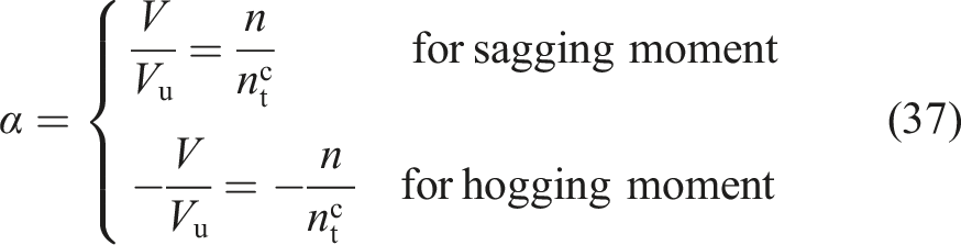

Finite element analysis and verification
Element selection and interaction settings
To validate the accuracy of the theoretical model, approximately 100 FE models were established. As shown in Figure 9(a), the shell element with four nodes calculated with reduced integration (S4R) was used to simulate the profiled steel parts and steel diaphragms (Zhang et al., 2025). The UHTCC slabs were simulated using the three-dimensional solid element with eight nodes calculated with reduced integration (C3D8R) (Tong et al., 2024). Considering that rebars primarily bear shear forces, the two-node linear beam element in space (B31) was used for simulation (Chen et al., 2025). Schematic diagram of FE model. (a) Mesh condition. (b) Interaction settings.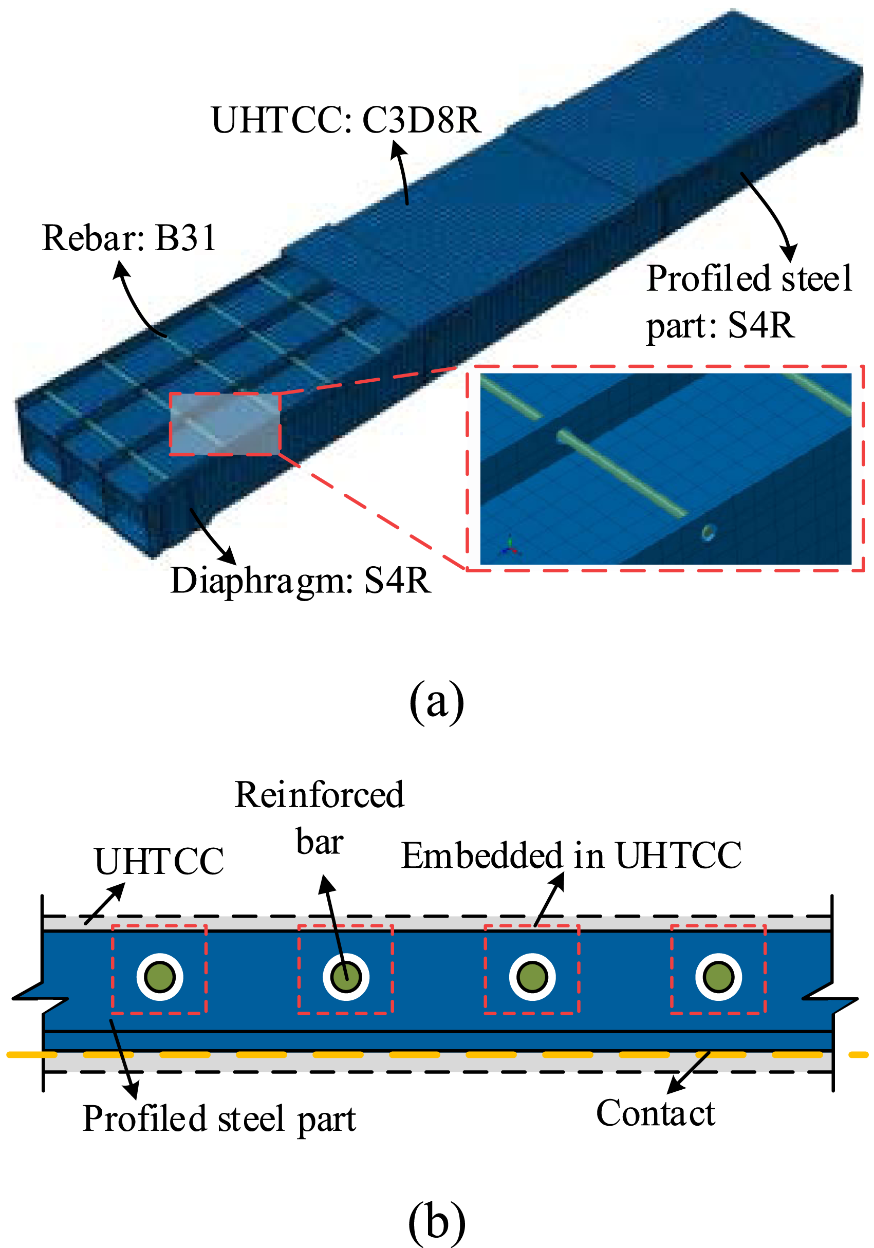
The interaction settings between components are shown in Figure 9(b). For the contact surfaces between the UHTCC slabs and the profiled steel parts, a “penalty” friction formula (with a friction coefficient of 0.2) was used for “contact” in the tangential direction, and “hard” contact was applied in the normal direction (Yu et al., 2025). For the PBL shear connectors, a small portion of steel plates near the PBL holes were embedded in the UHTCC slabs to simulate the interactions. The reinforced bars were also embedded in the UHTCC slabs.
Constitutive model
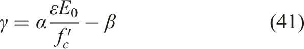
The constitutive material models for reinforced bars and steel plates were simplified (Wu et al., 2025; Yu and Tong et al., 2025), as shown in Figure 10(a). As depicted in Figure 10(b), the compressive constitutive model of UHTCC includes both ascending and descending stages, following the study of (Zhou et al., 2015). The relationship between stress σ and strain ε during the ascending stage under compression is defined by equation (39). Simplified constitutive material models. (a) Steel plates and reinforced bars. (b) UHTCC.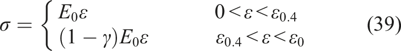


Since the ultimate tensile strain of UHTCC can generally reach 3%–6% (Xu et al., 2019), which exceeds the deformation capacity of CBD structures at failure, the tension softening is usually ignored in the tensile constitutive model of UHTCC (Wang et al., 2023). The post-peak tensile behavior of the UHTCC was characterized using a bilinear curve, based on analysis of the test results conducted by (Zhou et al., 2015), expressed as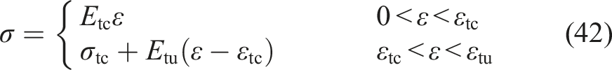
Mesh sensitivity test
Nine FE examples of W-Z specimen with different mesh sizes (among 10-150 mm) were established for the mesh sensitivity test, as shown in Figure 11. It can be seen that the FE models can well simulate the ultimate capacity of assembled steel-UHTCC CBDs when the mesh size was smaller than 75 mm. Based on the results of the mesh sensitivity test, the element sizes for the UHTCC slabs and profiled steel parts were set as 25 mm, while the element size for reinforced bars was set as 2 mm. Ultimate load of steel-UHTCC CBDs with different mesh sizes.
Verification of FE models
To verify the accuracy, FE models of four different types of proposed assembled steel-UHTCC CBDs were established and compared with experimental results (Chen et al., 2024), as shown in Figure 12(a)–(d). The thickness of the UHTCC slabs is 45 mm and the diameter of PBL shear connectors is 12 mm. Each specimen is welded from three duplicate profiled steel sections. Additionally, FE models of steel-UHTCC CBDs with stud shear connectors from experimental study of (Tong et al., 2023) were developed and validated to further confirm the accuracy of FE modeling method, as shown in Figure 12(f)–(g). Comparison of load-deflection curves between FE models and tests. (a) W-T. (b) W-Z. (c) W-B. (d) H-B. (e) A1 (Tong et al., 2023). (f) B1 (Tong et al., 2023). (g) U1 (Tong et al., 2023).
The load-deflection curves of the FE models and the experimental results match well. It is evident that all errors are within 10%, with the discrepancy in ultimate load generally being less than 5%. This minor deviation between the FE simulation results and experimental results suggests that the model can be further utilized to validate the accuracy of theoretical analysis.
Accuracy of flexural resistance formulas
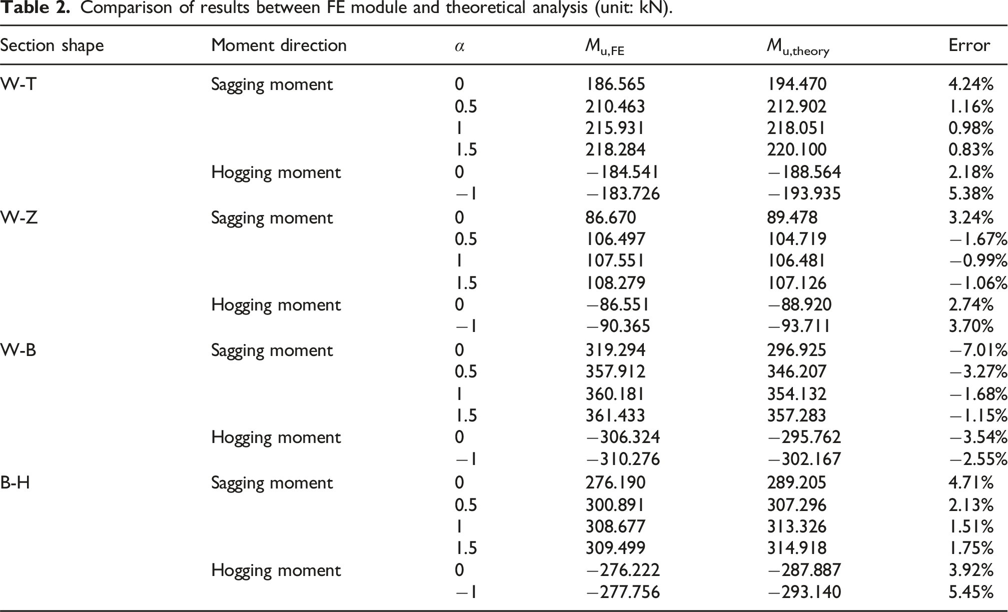
To simulate the impact of different degrees of shear connection on the ultimate flexural capacity, numerous FE models with four different types of profiled steel parts were established. Figure 12 presents a comparison between the results of FE simulations and theoretical calculations. In this comparison, the number of PBL shear connectors, n, is transformed into a normalized parameter α, as expressed in equation (39), to contrast the differences in flexural capacity under different degrees of shear connection (Figure 13). Comparison of relationship between different shear connection degrees and ultimate flexural capacity between FE models and theoretical model. (a) W-T. (b) W-Z. (c) W-B. (d) H-B.
The curves indicate that under sagging moments, the ultimate flexural capacity Mu increased more rapidly when the number of PBL shear connectors is very low (α = 0 - 0.5). In this range, the shear connectors theoretically reach their ultimate shear capacity and undergo plastic deformation. When α exceeding 0.5, the growth rate of Mu slows down as the shear connectors work within their elastic range. With the increase in shear-slip stiffness at the interface between UHTCC and steel plates, the efficiency of internal stress distribution within the composite structure is mildly enhanced, which leads to a slight increase in the overall ultimate flexural capacity. Maintaining the normalized PBL shear connector number α between 0.5 and 1 is optimal to achieve a fine ultimate flexural capacity of assembled steel-UHTCC CBDs while ensuring economic efficiency in engineering applications. For instance, reducing α from 1.5 to 0.5 in a W-T CBD could cut down PBL shear connector counts by 67%, significantly decrease the steel usage and welding time while retaining 96% of the flexural capacity, thereby decrease on-site construction requirements, which is expected to save costs. In addition, reducing unnecessary cutting and welding can also enhance the fatigue resistance of steel structures.
The positions of yield load and ultimate load under sagging moments, as determined by theoretical analysis, are illustrated on the load-displacement curves obtained from FE simulations in Figure 14. Comparison of theoretical ultimate and yield load and load-deflection of FE model (W-Z, α = 1.5).
When under hogging moments, the UHTCC slabs will be subjected to tension, crack or even fracture. Given that the tensile strength of UHTCC is significantly lower than its compressive strength, the contribution of UHTCC plates to flexural resistance is extremely limited. Therefore, under hogging moments, only a minimal number of PBL shear connectors are required to achieve full shear connection, and further increasing the number of PBL shear connectors does not significantly affect the ultimate flexural capacity of assembled steel-UHTCC CBDs.
Comparison of results between FE module and theoretical analysis (unit: kN).
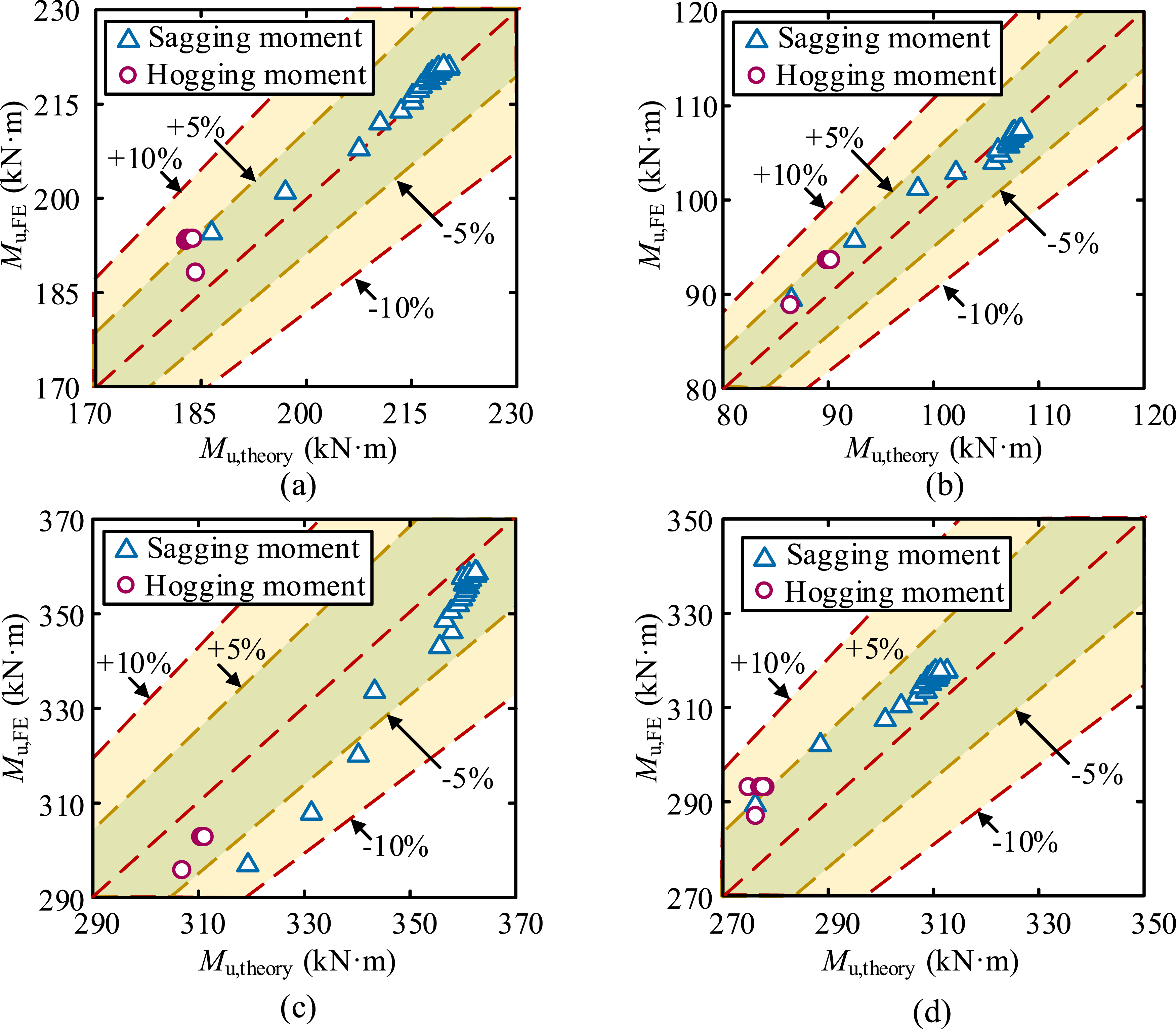
Accuracy of theoretical formula compared to simulated values. (a) W-T. (b) W-Z. (c) W-B. (d) H-B.
Conclusion
The flexural behavior of assembled steel-UHTCC CBDs using PBL shear connectors under different degrees of shear connection has been studied through theoretical analysis and FE simulation. The following conclusions can be summarized. (1) A theoretical formula to calculate the ultimate flexural capacity of assembled steel-UHTCC CBDs based on partial interaction theory has been developed. It accounts for the shear-slip effects of PBL shear connectors and is capable of predicting the ultimate flexural capacity of assembled steel-UHTCC CBDs under both sagging and hogging moments. (2) FE models of a novel assembled steel-UHTCC CBD were established using ABAQUS to investigate their flexural behavior. This model was compared with experimental results to validate the accuracy of the FE simulations. (3) A comparison and validation between the theoretical analysis and FE simulation results have been conducted, confirming the accuracy of the theoretical model. The discrepancy between the theoretical analysis and FE simulation results is relatively minor, not exceeding 10%, with most deviations within 5%. (4) Based on the results from FE simulations, it has been identified that maintaining the normalized PBL shear connector number α between 0.5 and 1 in engineering applications is optimal to achieve a fine ultimate flexural capacity of assembled steel-UHTCC CBDs while giving consideration to economic efficiency and fatigue resistance.
Footnotes
Funding
The authors disclosed receipt of the following financial support for the research, authorship, and/or publication of this article: This study was funded by the Natural Science Foundation of Zhejiang Province (Grant no. LR24E080002), the National Natural Science Foundation of China (Grant no. 51978607, 52108180).
Declaration of conflicting interests
The authors declared no potential conflicts of interest with respect to the research, authorship, and/or publication of this article.