




Abstract
Traditionally, straddle-type track beams require considerable depth to accommodate stabilizing wheels of monorail, resulting in greater self-weight and adverse visual impact. To address these shortcomings, this paper proposed dual-steel-shell concrete (DSSC) straddle-type track beams with the inverted-T shaped section, which eliminates stabilizing wheels and symmetrically arranges the running wheels to ensure lateral stability of the monorail. In this innovative configuration, studs must simultaneously resist interfacial shear slip and separation forces (e.g., steel buckling mitigation). The push-out tests and finite element (FE) analyses were conducted on the specimens with 16 mm diameter stud. The results demonstrated that tension induced a degradation in shear capacity and stiffness of studs. When subjected to 60% of the tensile capacity, the shear capacity and stiffness of tension-shear specimens decreased by 23.78% and 21.96% compared with the pure shear specimens. For strength of concrete exceeding C50, the shear capacity remained essentially constant. The developed theoretical formula integrating stud bending angle and effective deformation length demonstrated excellent agreement with experimental and FE results. These findings establish reliable design criteria for DSSC structures.
Keywords
Introduction
A traditional straddle-type monorail system consists of three tire components, namely running tires, guiding tires, and stability tires (Kato and Yamazaki, 2004), as shown in Figure 1(a). This system has been adopted in cities such as Tokyo (Kishi, 2005), Chongqing (He, 2015), and Kuala Lumpur (Das and Yukawa, 2013; Mohamad, 2003) owing to its advantages of low noise and terrain adaptability. However, the conventional design is subject to several limitations. The stability tires require a higher track beam profile, which increases material costs and exacerbates visual intrusion in urban environments (Miller and Wirasinghe, 2014). Track beam of the straddle-type monorails system. (a) Traditional track beam-vehicle relationship. (b) Novel track beam-vehicle relationship.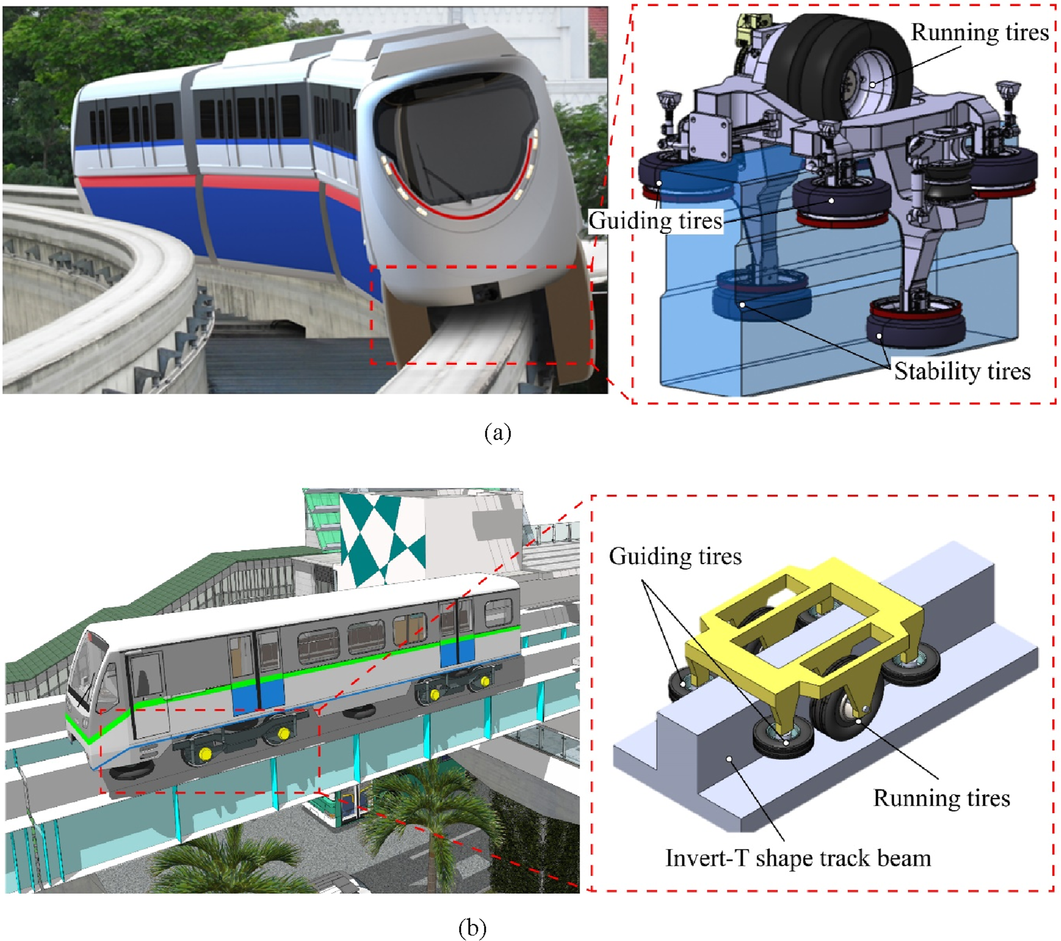
To address these issues, the novel track beam-vehicle relationship was proposed (Figure 1(b)). By eliminating stability tires and symmetrically positioning running tires on both beam flanges, this novel track beam-vehicle system reduces beam height, improves lateral stability, and provides aesthetic benefits.
In this innovative relationship, the inverted-T-shaped section is required for the track beam. The existing structural forms are not suitable for the inverted-T section due to the narrow compressive region. Specifically, a pure steel structure is prone to local buckling of the upper steel plate under compression. Furthermore, the beam’s self-weight increases considerably in a reinforced concrete structure, while the limited compression zone complicates reinforcement arrangement. To meet the structural demands, a dual-steel-shell concrete (DSSC) structure was proposed (Figure 2), where steel shells are connected to infilled concrete via studs (Jiang et al., 2025; Luo et al., 2025; Zou et al., 2025). This configuration enhances structural performance in two ways. Firstly, the concrete infill and studs effectively delay buckling failure of the steel shell by providing lateral restraint. Secondly, the composite action between concrete and steel increases the compressive resistance and enhances structural stiffness. The proposed DSSC structure meets the requirements of novel straddle-type track beams and shows promise for broader engineering applications. Its steel-concrete composite design and efficient stud-based load transfer mechanism make it particularly suitable for compression-dominant structures with space-constrained cross-sections, such as lightweight bridge piers and irregular structural components. However, studs in DSSC structures face a critical challenge. They must simultaneously resist slip at the concrete-steel interface and separation forces generated by steel shell buckling (Avci-Karatas, 2022; Mo et al., 2021; Song et al., 2023). Consequently, studs are subjected to a coupled shear-tension loading. Dual-steel-shell concrete structure for novel straddle-type track beams.
Summary of previous studies.
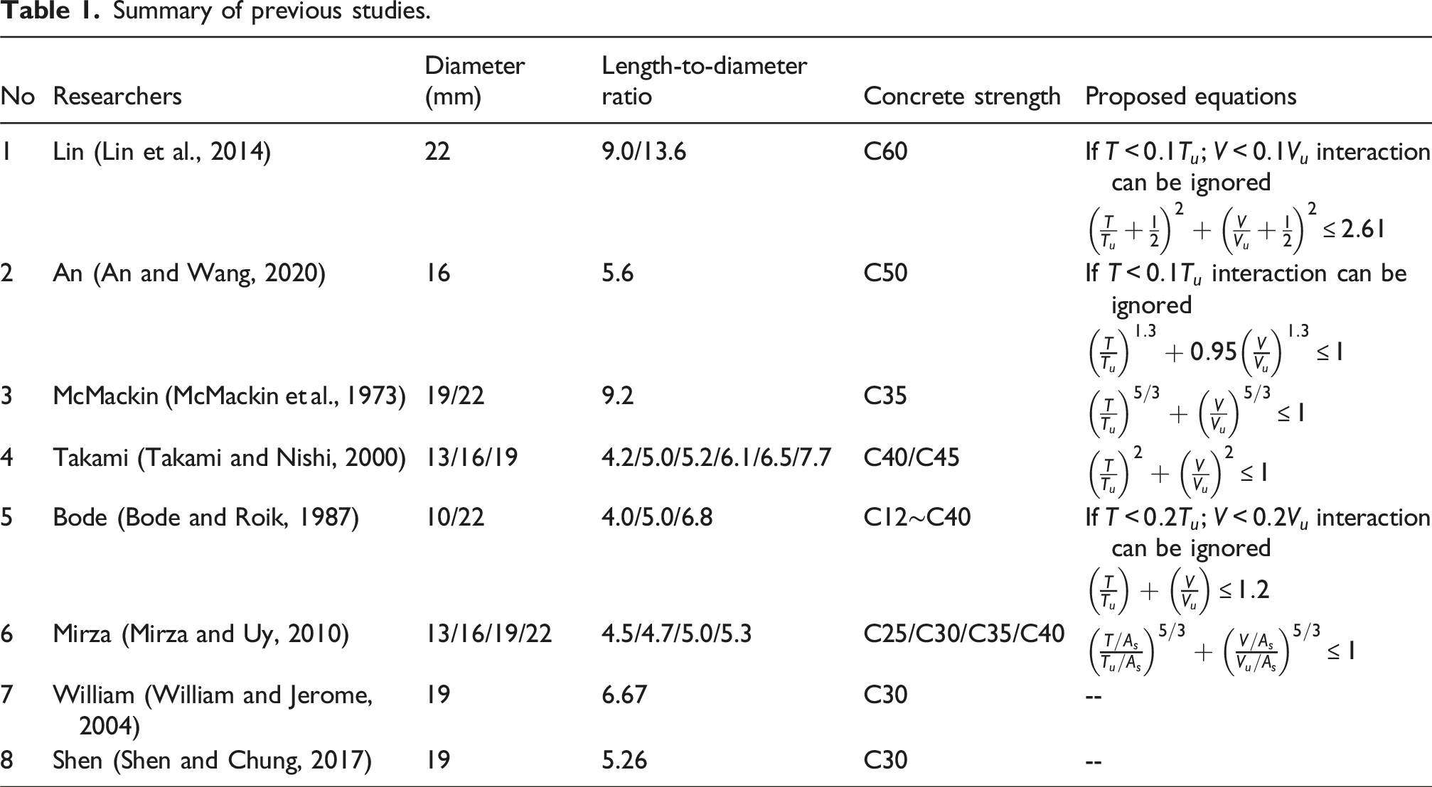
In this study, the push-out specimens with C80 concrete were fabricated and tested. The validated FE model was established to analysis with the parameters of the level of tension load and concrete strength.
Experimental programs
Details of specimens
A total of 10 specimens were adopted in the test and FE analysis to investigate the shear behavior of studs under combined shear-tension loads. Tests focused on high-strength C80 concrete, comprising pure tension specimens, pure shear specimens, and shear-tension specimens subjected to tensile force of 20%, 30%, and 40% of the ultimate tensile capacity. All the test specimens were designed with consistent geometric parameters, including a stud with 16 mm diameter and length-to-diameter ratio of 7.5. Based on the test specimens, a FE analysis was further carried out to extend concrete strengths (C50, C60, C70) and tension load (40%–60% of the ultimate tensile capacity).
A nomenclature system was adopted for all the specimens. Specifically, the specimens are referred to as N/T-D16-C i -T j -1/2, where N or T represents the specimens from test or FE analysis, respectively; D16 indicates that the diameter of the stud is 16 mm; C i represents the strength of the concrete; T j represents the level of the tension load; 1 or 2 indicates two different specimens with the same parameters. For instance, T-D16-C60-T20-1 is used to represent the studs subjected to 20% of the ultimate tensile load, embedded in C60 concrete with a stud diameter of 16 mm.
The dimensions of the test specimens are shown in Figure 3. For the tension specimens, the studs were welded onto a 20 mm thick steel plate and were then embedded in a concrete block measuring 500 mm in length, 500 mm in width, and 250 mm in height. The stiffener with the 300 mm in length and 12 mm in thickness was welded to the bottom of the steel part to prevent local buckling during loading. The studs were 120 mm in height, with a cap diameter of 28 mm and a cap thickness of 8 mm. Concrete blocks of identical dimensions were used for the pure shear and shear-tension specimens. Different from the tension specimens, the studs in pure shear and shear-tension specimens were symmetrically welded to steel parts. The reinforcement layouts of all the specimen were consistent. Specifically, the stirrups, measuring 210 × 300 mm, were fabricated from 8 mm-diameter HRB400 rebars, while the longitudinal rebars consisted of 12 mm-diameter HRB400 rebars with a length of 300 mm. The dimensions of the test specimens. (a) Pure tension specimens. (b) Pure/shear-tension specimens. 
Fabrication of specimens
The specimens were fabricated in three stages. In the first step, studs were welded onto the steel parts. In the second step, the formwork was installed and the reinforcement cages were then assembled. Finally, the high-strength concrete was cast. The formwork of the specimens was demolded after 7 days of curing under ambient outdoor conditions.
Materials properties
Materials properties.
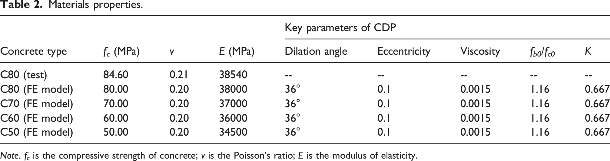
Note. f c is the compressive strength of concrete; v is the Poisson’s ratio; E is the modulus of elasticity.
Steel materials properties.

Note. f y is the yield strength; f u is the ultimate strength; E is the modulus of elasticity.
Testing setup and instrumentation
The instrumentation layout of the push-out test is shown in Figure 4. Two 20-t hydraulic jacks were symmetrically arranged between the concrete and the steel to apply the tensile load to the studs (Figure 4(a)). To guarantee that both jacks apply the same pressure, they were connected to a single oil pump equipped with a flow divider. For the pure shear specimens, as shown in Figure 4(b), the 20-t hydraulic jack was arranged, which could apply the shear load to the studs. For the shear-tension specimens, as shown in Figure 4(c), the same testing method as the pure shear specimens was used. However, the horizontal hydraulic jacks were arranged to apply tensile loads. The linear variable differential transformers (LVDTs) were arranged to measure the slip between the concrete slab and steel part. The load cells were employed to measure the shear or tension load. Instrumentation layout. (a) Pure tension specimens. (b) Pure shear specimens. (c) Shear-tension specimens.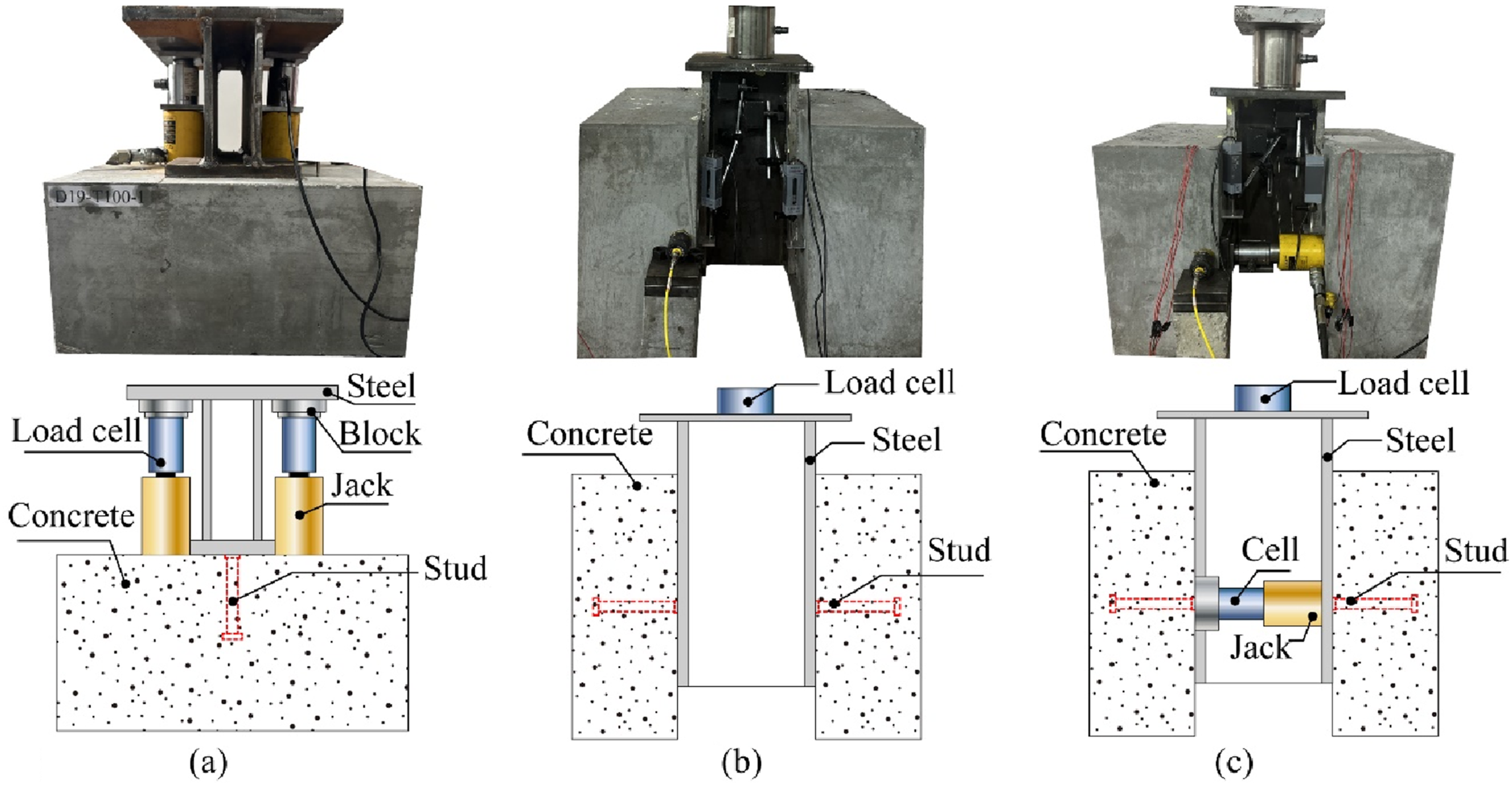
Numerical simulations
Parameters
In FE model, different levels of tensile loading and concrete strengths were considered to further investigate their effects on the shear behavior of studs. Specifically, the applied tensile load was varied from 20% to 60% of the ultimate tensile capacity, while the concrete strength was set to C50, C60, C70, and C80.
Finite-element (FE) model
Finite-element type and mesh
The FE model consisted of rebars parts, steel parts, concrete parts, and stud parts. The solid element (C3D8R) was used to model the steel, concrete, and stud parts, while the rebars were simulated using the two-node linear truss element (T3D2). A fine mesh with an element size of 3 mm was applied to the studs and the stud hole in concrete, whereas a coarse mesh of 10 mm was adopted for the steel and concrete parts.
Contact and boundary condition modeling
In FE model, contact pairs were defined at the concrete-stud and concrete-steel interfaces. Surface-to-surface contact was adopted for these interfaces, with a friction coefficient of 0.6 (Wang et al., 2023; Wang et al., 2024). The interaction between the steel plate and concrete (to apply the tension load) was defined as “Tie” constraints, while the interaction between the rebars and concrete was defined as the “Embedded” constraints.
The boundary condition in FE model is shown in Figure 5. For the pure tension specimens, the bottom of the concrete slab was constrained in all the directions (i.e., U1=U2=U3=UR1=UR2=UR3). For the pure shear and shear-tension specimens, a symmetric boundary condition was employed along the x-axis (i.e., XSYMM: U1=UR2=U3=0). The boundary condition of the bottom of the concrete parts was constrained in all the direction except the direction of the tension load (i.e., U2=U3=UR1=UR2=UR3=0). The displacement-controlled method was applied to the RP along the z-axis direction for pure tension specimens. For the pure shear, the shear load was applied in the z-axis direction with displacement-controlled method. For the shear-tension specimens, the tension load was applied as a fixed value using the force-controlled method in Step 1, with an initial increment size of 0.001. Step 2 was then performed using the displacement-controlled method, with an initial increment size of 0.0001. The details of the studs basing on FE model. (a) Details of FE model (pure tension specimens). (b) Details of FE model (pure shear/shear-tension specimens).
Materials modeling
The constitutive of the studs, rebars, concrete, and the steel is shown in Figure 6. The bi-linear constitutive was adopted for the rebars and steel while the tri-linear-constitutive was used to the studs. Concrete damage plasticity (CDP) model was adopted to model the concrete. The parameters in the CDP model were set as follows: dilation angle = 36°, eccentricity = 0.1, viscosity parameter = 0.0015, f
b0
/f
c0
= 1.16, and K = 0.6667. The stress-strain constitutive model of the concrete based on GB50010-2010 (Ministry of Transport of the People's Republic of China, 2015) was selected in CDP. Materials modeling of studs, steel, and concrete. (a) Trilinear constitutive for studs. (b) Bi-linear constitutive for rebars. (c) Bi-linear constitutive for steel. (d) Constitutive of concrete.
Validation
The load-displacement curves of FE model were compared with those of test specimens. As shown in Figure 7, the comparison results demonstrated that the load-displacement curves obtained from the FE model exhibited good agreement with the experimental results, which confirmed the reliability of the FE model. Comparison of the loading-displacement curves. (a) Pure shear specimens. (b) Specimens at 20% tensile capacity. (c) Specimens at 30% tensile capacity. (d) Specimens at 40% tensile capacity. (e) Pure tension specimens.
Results and discussion
Summary of tested results of specimens.

Failure modes
The failure modes of pure tension specimens, pure shear specimens, and shear-tension specimens are shown in Figure 8. The failure modes of all the specimens involved stud shearing (or tension fracture). As shown in Figure 8(a), the concrete remained undamaged, while pronounced necking was observed at the stud fracture location in tension specimens. For pure shear and tension-shear specimens, the concrete beneath the studs exhibited localized spalling caused by shear compression but showed no visible cracking. This demonstrated that the concrete could resist shear deformation of studs. The failure modes of studs under varying tension load levels (20%, 30%, 40% of the ultimate tensile strength) are shown in Figure 8(b). It was evident that as the tensile force increased, necking occurred at the root of the studs. Failure modes of studs. (a) Steel and concrete surface. (b) Stud failure.
Shear capacity
Figure 9(a) shows the effects of concrete strength (C50 to C80) on the shear capacity of the pure shear and shear-tension specimens. The results indicated that increasing the tension load significantly decreased the shear capacity. When studs embedded in C50 concrete were subjected to 20%, 30%, 40%, and 60% of the ultimate tensile capacity, their shear capacity decreased by 4.50%, 10.00%, 15.78%, and 23.78%, respectively, relative to the pure shear specimens. The shear capacity of studs shows limited sensitivity to concrete strength once the concrete grade exceeds C50. The failure mode of push-out specimens was characterized by stud shearing, indicating that concrete with a strength above C50 provides sufficient resistance to stud shear deformation. Therefore, increasing the concrete strength has little effect on the shear capacity of push-out specimens, as it is primarily governed by stud strength. Shear capacity and stiffness of push-out specimens under different level of tension load. (a) Shear capacity. (b) Shear stiffness.
Shear stiffness
Figure 9(b) shows the shear stiffness at different tensile load levels (20%∼60% of ultimate tensile capacity) in varying concrete strength. The shear stiffness of specimens was defined as the slope of the load-displacement curve at a slip value of 0.2 mm (Oehlers and Coughlan, 1986). The results indicated that the shear stiffness of the studs was reduced by increased tension load. For instance, compared to pure shear specimens, shear stiffness reductions of 10.98%, 13.22%, 15.61%, 17.57%, and 21.96% were observed in studs embedded in C50 concrete when subjected to tension load level corresponding to 20%, 30%, 40%, 50%, and 60% of the ultimate tension capacity, respectively. Additionally, the shear stiffness was influenced by the concrete strength. At an applied tension load of 20% of the ultimate tensile capacity, the shear stiffness of shear-tension specimens with C80 concrete was 5.4% higher than that of the C50 specimens. This increase was attributed to the greater stiffness of C80 concrete, which led to an increase in shear stiffness.
Shear capacity of studs under combined shear and tension loads
Mechanical model for studs under coupled shear and tension loads
The test results indicated that the tension load applied to the studs could effectively reduce the shear capacity of the studs. According to An (An and Wang, 2023), tension load generates an additional vertical shear component (△F, shown in Figure 10). This additional force increases the stud’s actual shear force to F
e
+△F. Therefore, this interaction reduces the stud’s shear capacity (Ferrero, 1995). As shown in Figure 10, the magnitude of △F depends on two parameters, namely the bending angle (α) of the stud’s deformed shape and the tension force magnitude applied to the stud. Mechanical analysis model for stud under coupled shear and tension load.
Formula for studs under combined shear and tension loads
The results demonstrated that the failure mode of all the specimens consistently involved stud fracture. Therefore, the pure shear capacity of studs can be expressed as A
S
f
u
. The shear capacity of studs under tension load was given by equation (5-1). The derivation process of equation (5-1) is presented in Appendix A. These equations, derived in a previous theoretical study, were validated through experimental and FE results in this study.
Based on the studies by Mindlin (Mindlin, 1936), δ can be calculated as follows:
Statement on the applicability of the formula
The following assumptions were listed as follows. (1) A length-to-diameter ratio greater than 7.5 is assumed for the stud, ensuring that tensile failure occurs by stud fracture rather than by concrete pullout or breakout (Gao et al., 2024). (2) The concrete strength is assumed to exceeds 50 MPa to guarantee that shear failure of studs under loading (Sutton et al., 2014; Xue et al., 2008; Yang et al., 2019; Zhai et al., 2018). (3) The tensile force on the stud is assumed to be limited to 60% of its ultimate tensile capacity.
Verification of the computational theory
Theoretical calculations and FE/experimental results are compared in Figure 11. The average ratio of theoretical to experimental and numerical results was 1.01, with a standard deviation of 0.03. The comparison results showed that the proposed formula accurately predicted the shear capacity under a tension load and provided a reliable theoretical basis for evaluating the shear–tension behavior of studs. Comparison between theoretical and experimental or numerical results.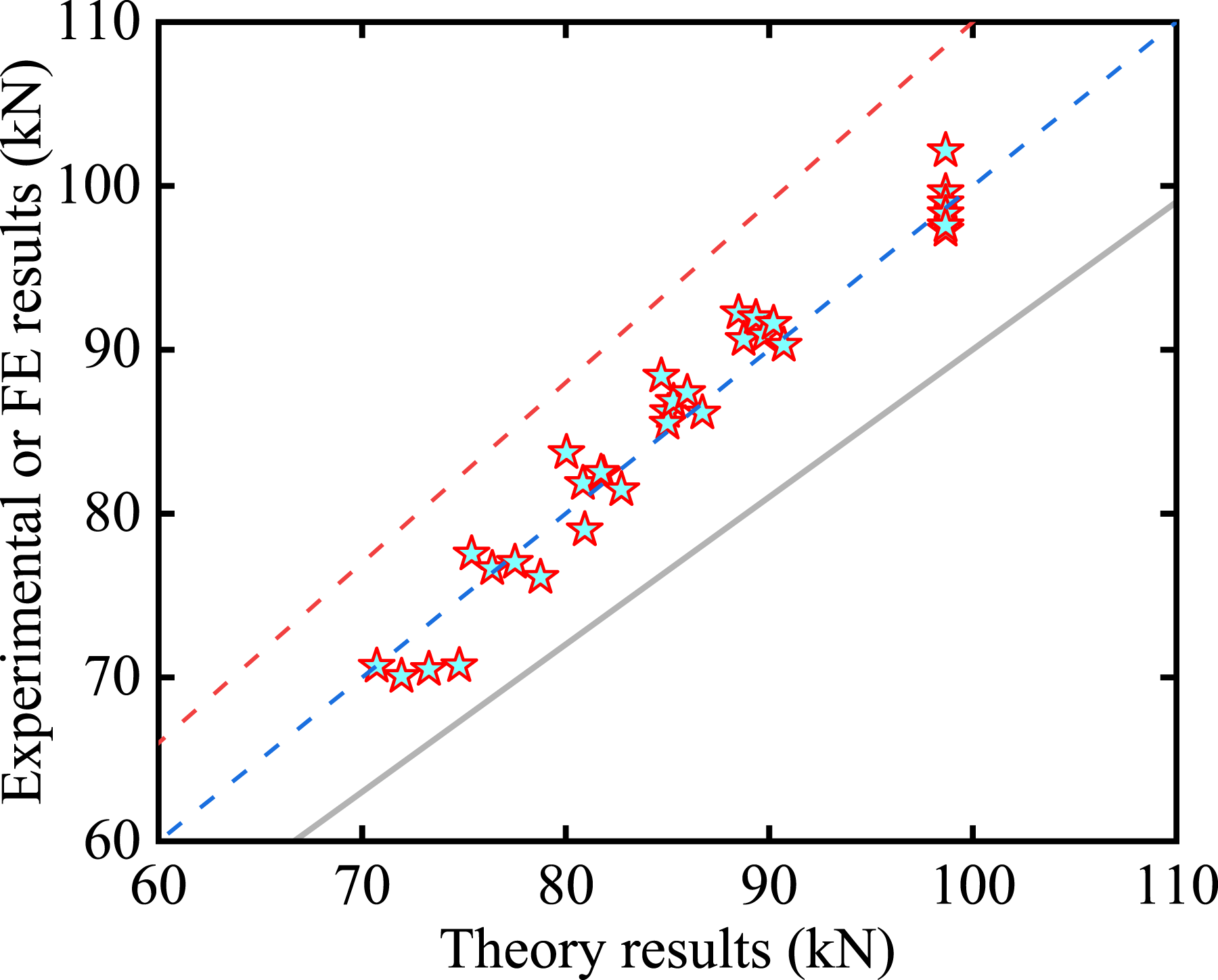
Conclusions
This study systematically investigated the shear-tension behavior of studs in novel dual-steel-shell concrete (DSSC) structures through experimental, numerical, and theoretical methods. The main conclusions are as follows: (1) Concrete damage was confined to the localized compression zones at stud roots, and no obvious cracks were observed. This confirms that high-strength concrete effectively resists shear-induced stud deformation. Shear-tension specimens exhibited elongation at stud roots. (2) Shear capacity and stiffness of studs were markedly reduced under tension load. When subjected to tensile force at 60% of the ultimate tensile capacity, studs embedded in C50 concrete exhibited reductions of 23.78% in shear capacity and 21.96% in shear stiffness. This degradation was attributed to the additional vertical shear component (△F) induced by tensile loads, which amplified the actual shear force on studs. (3) A mechanical model for the studs under combined shear and tension loads was verified. This formula demonstrated excellent agreement with the FE and experimental results, showing an average ratio of the calculated results to the FE and experimental results of 1.01. (4) This study introduces a DSSC track beam with an inverted-T cross-section. The DSSC uses steel-concrete composite action and stud-based load transfer to provide a material-efficient solution for space-constrained, compression-dominated systems such as bridge piers or columns.
Footnotes

Funding
The authors disclosed receipt of the following financial support for the research, authorship, and/or publication of this article: The authors would like to acknowledge financial support from the Guangzhou Municipal Science and Technology Project (Project No. 2025A03J3113); the National Natural Science Foundation of China (Project Nos. 52178278); and the Department of Education of Guangdong Province, China (Project No. 2021KCXTD030).
Declaration of conflicting interests
The authors declared no potential conflicts of interest with respect to the research, authorship, and/or publication of this article.