



Abstract
The use of bolts as shear connectors in cold-formed steel composite beams allows a deconstructed assembly to be fabricated, in addition to being compatible with other components. This makes it easier to demolish and create less waste, as well as being able to repair and replace steel beams during structure life if necessary. To design a safe and economical composite beam, a minimum degree of shear connection must be provided. For some specific sections such as steel beam sections with equal flanges or with different flanges, this coefficient is prescribed by the design codes. Also, the bending resistance of composite beams with different degrees of shear connection can be estimated using the equilibrium method within the composite section. However, there are very few studies investigating the minimum degree of shear connection for cold-formed composite beams with profiled steel sheeting. In this paper, numerical simulation results are presented highlighting parameters that affect the structural performance of partial shear connections in the composite beams with profiled steel sheeting. Some available experimental results were taken into account to validate the numerical modeling. Then, the influences of load configuration, span length, geometry, and cross-section of composite beams were investigated. Finally, a minimum required degree of shear connection is formulated for this type of composite beam and ranges from 0.1 to 0.7, depending on the beam span.
Keywords
Introduction
Due to the possibility of buckling in the compression zone of cold-formed steel (CFS) beams under bending, using steel sections alone is not a desirable option. Therefore, the use of composite beams due to their high initial stiffness and strength and their low deflection in mid-span have been increased widely in the construction industry in recent decades, particularly in concrete flooring systems (Dar et al., 2023; Xu et al., 2022; Zeynalian, 2015; Zeynalian et al., 2016, 2018). It is necessary to mention that between the concrete slabs and CFS sections, shear connectors serve as transferors of shear forces, which allow composite action on the whole section in which the concrete slab is in compression and CFS section is in tension (Ataei and Zeynalian, 2021). As a result, the CFS section is prevented from buckling (Alhajri et al., 2016; Dias et al., 2021). It is worth mentioning that studs, channels, and bolts are examples of shear connector types. In the late 1960s, Dallam (1966) studied bolted shear connectors for composite beams. Based on 12 push-out tests, he demonstrated that bolted connectors have a much higher load-carrying capacity than stud shear connectors.
Bolted connectors are among the most common types of connectors used with cold-formed composite beams. By using bolts as a cold formed composite beam connector, in addition to compatibility with other components and no need to weld, the steel beam can be separated during the life cycle in case of necessity (Ataei et al., 2023; Ataei and Zeynalian, 2021). This provides less waste and easier reinstallation and they are especially a suitable option for short-term buildings that require quick demolition. Several studies (Ataei et al., 2023; Ataei and Mahmoudy, 2024; Hosseinpour et al., 2022, 2023; Shakarami et al., 2023) were conducted on this type of connection used in composite cold-formed steel beams.
The degree of shear connection (η) refers to the amount of shear transfer between the connector and the concrete slab compared to a full shear connection (η = 1), which was first expressed by Oehlers et al. (1997). To be safe and economical, composite beams must have a minimum threshold of this coefficient (ηmin). Hence, this research studied 90 composite beams with different shear coefficients and specific cross-sections to obtain a relationship for introducing a minimum shear coefficient based on the span length.
According to the European code 4 (2004), if the steel cross-section passes some limits in a composite beam, which is demonstrated in Table 2–5 of the code, it is possible to use the plastic stress distribution method to analyze the composite beam. By assuming the composite performance between the concrete slab and the cold-formed steel section, it is expected that due to the small area of CFS sections, the neutral axes will often lean towards the concrete slab, and the steel section will be completely in tension. Thus, the plastic stress distribution method is applicable for CFS composite beams. Nie et al. (2008) conducted three categories of experimental study on composite beams for determining the minimum required degree of shear connection. Simple supported composite beams with positive and negative moments were tested in categories A and B. Category C included five composite beams, of which four specimens were tested. Among them were two-span beams, and one specimen was a three-span beam. According to these studies, the degree of shear connection varies between 0.25 and 1.85, with the majority below EC4 prescriptions. Classen (2018) studied the structural characteristics of partial shear connections for composite steel beams with T sections. These studies led to the expansion of EC4’s prescriptions related to ηmin, for the composite beams with T sections. While he used the same method as EC4’s numerical simulation, instead of focusing on, for example, 6 mm for connector deformation capacity, other deformation capacities such as 3.5, 5, 6, 10, and 21 mm were also investigated. The study also investigated different sections having different ratios of plastic moments of steel sections to composite plastic moments (Mpl,bare/Mpl,R,FSC) such as 0.1 to 0.2.
Another investigation of the composite beam connection was conducted by Guo et al. (2019) by defining a minimum threshold of the partial shear connection (ηmin). They proposed a minimum degree of shear connection to prevent shear connection failure under the bending moment of the beam. Additionally, using the component-based method model and comparing the results with experimental data, they demonstrated that computational models can estimate the internal stiffness and internal moments of column connections as well as composite beams with partial shear connections.
Aggelopoulos et al. (2018) investigated the minimum degree of shear connection for beams that are mostly neglected in the codes, including non-reinforced beams. After validating the finite element models of the mentioned method, using experimental methods, the parametric study of these beams was conducted for spans ranging from 9 to 18 m finally, EC4 relationships were modified. They also stated that when this coefficient is less than that proposed in EC4, the sliding effect should also be considered in beam deformation. This also has been considered in (Couchman, 2015; Lawson et al., 2017). Kyvelou et al. (2017) investigated the behavior and characteristics of composite slabs with cold-formed steel beams and wooden slabs. They provide some suggestions for designing such composite slabs. For the composite members, a focus was made on the calculation of the partial shear connection coefficient and their shear adhesion coefficient. This is a function of the geometry and material properties of the components and connectors.
Theoretical background of partial shear connection
A plastic design method is generally considered to assess the bending resistance of steel composite beams according to codes such as EC4 (2004). In this method, it is assumed that each fiber of the steel section is stressed up to its yield strength f
y
, fibers in the compression zone of concrete are stressed to 0.85 f′c, and the shear connectors are stressed to their ultimate shear resistance PR. In the composite beams, full shear connections are distinguished from partial shear connections (Oehlers et al., 1997), illustrated by an index nominated as the degree of shear connection (η). The degree of shear connection changes from 0 (no shear connection) to 1 (full shear connection). In the case of ductile shear connectors, the degree of shear connection is defined as the ratio between the provided shear connectors (n) and the number of connectors needed for full shear connection (nf) (Eurocode 4, 2004). In Figure 1, bending resistance is plotted against the degrees of shear connection with partial shear connections due to plastic design method (equilibrium method). Mpl,R of the composite section is the same as Mpl,bare of the pure steel section for beams with no shear connections (point A). In beams with full shear connections (point C), the maximum steel and concrete strength as well as the highest bending resistance (Mpl,R = Mpl,R,FSC) are achieved. In this case, one plastic neutral axis (P.N.A.) is present in the strain profile whose position may be determined by setting equal tensile strength and compression strength of the section. It is common for beams with partial shear connection (point B) to have two P.N.A, as demonstrated in Figure 1, with a large strain across the interface between steel and concrete. Diagram showing partial shear connections calculated using equilibrium method (left), corresponding stress profiles (right).
It should be noted that in this study, as shown in Figure 1, the starting point is point A′ instead of point A, which is related to Mbare instead of Mpl,bare, which is also used by Kyvelou et al. (2017) for calculating the moment capacity of the composite system using the same method.
By the equilibrium method, plastic bending resistance depends on the cross-section geometry, the strength of the material, and the degree of partial shear connection in the cross-section. However, structural system parameters (for instance, beam span and load configuration), shear connector slip, and deformation capacity are not considered.
Partial shear connection
The plastic design method is based on only the concept of force equilibrium; but material deformations in the connectors are completely ignored. However, there is significant relative deformation (slip) between the steel beam and concrete slab in composite beams with partial shear connections (Nie and Cai, 2003; Oehlers and Sved, 1995). Notably, ignoring these deformations could result in an unsafe design. When the bending resistance Mpl,R calculated using the plastic design method is equal to the flexural strength Multimate of the composite beam, the deformation capacity of the connectors δu is the same as the occurring beam slip δbeam. This level of partial shear connection is defined as the lower limit for using partial shear connections in the method “minimum degree of shear connection” ηmin. A value greater than this in composite beams leads to a safety design. Thus, in design codes, procedures for plastic design methods in composite beams are limited to cases in which the degree of shear connection provided exceeds this minimum value.
For deriving ηmin, two methods are available: first, by evaluating slip in the interface between slab and steel beam δbeam,max at ultimate load and deformation capacity of the shear connector. This method was first proposed by Becker (1997). Second, by considering Multimate = Mpl,R, as suggested by Aribert (1992). It is necessary to mention that researchers have widely employed the latter (Classen, 2018; Classen and Herbrand, 2016). Classen states that maximum slip is not always achieved at the beam end. When the steel beam reaches its yield strength, the maximum slip location may move slightly from the beam end to the yielding zone. As a result, evaluating beam end slips may yield unsafe results. Hence, in this research, the second method is considered for comparing FE flexural strengths and bending resistance through the equilibrium method.
Code provisions and limitations
As an example, partially shear connections provided in EC4 are criticized by numerical simulations performed by some researchers. The prescriptions are valid for the specific cases because of restrictions that simplify the code, such as using connectors with a minimum deformation capacity of 6 mm and steel beam sections with equal flanges or with different flanges. However, calculating the minimum degree of shear connection is considered for beams with special geometry such as T-beams (Classen, 2018).
Research program and methodology
An investigation of the partial shear connections for cold-formed composite beams with profiled steel sheeting is presented in this paper. This paper follows the EC4 methodology, meaning ηmin is derivated similarly using numerical simulations. This study examined three different group specimens of composite cold-formed steel cross sections, including A, B, and C, as demonstrated in Figure 2 and Table 1. The specimens comprised different ratios of steel profile Mpl,bare plastic bending resistance to composite section Mpl,R,FSC plastic bending resistance (Mpl,bare/Mpl,R,FSC = 0.25, 0.30, 0.37). It is necessary to mention that for each specimen group, different lengths of 3, 6, and 8 m under two concentrated loads in the middle were examined. For all composite beams, the distance between the loads is constant (970 mm), as illustrated in Figure 2. The composite beams were supported (pinned-roller), and during the study, other factors such as concrete and steel’s properties and thickness, and profiled steel sheeting remain constant. Figure 3 shows the degree of partial shear connections calculated based on the mean material properties of categories A, B, and C. The procedure is outlined as follows: • First, with the FE model validated for analyses of a specific beam, the degree of shear connection is gradually reduced from 1 to 0, evaluating corresponding Multimate,FE. • Employing the equilibrium method, the minimum degree of shear connection for the composite beam is determined by comparing the flexural strength Multimate,FE evaluated by FEM with the plastic bending resistance Mpl,R. The diagram of the degree of shear connection is demonstrated in Figure 3. When Mpl,R = Multimate,FE, the minimum degree of shear connection is found (see the Partial Shear Connection section, Method 2). • Then, FE-parametric analysis of the degree of shear connection is carried out systematically for various cross sections (i.e., A, B, and C), loading configurations (including concentrated load, uniform load), and beams with various spans Le. Table 2 presents the range of the studied parameters. It is necessary to mention that steel (fy = 300 N/mm2) and concrete (f′c = 30 N/mm2) material properties have remained constant throughout all parameters. • Finally, conclusions are drawn from nonlinear FE analyses of composite beams with different values of the ratios Mpl,bare/Mpl,R,FS and engineering models are developed for determining the minimum degree of shear connection. Configuration of the composite beam. Detailed parameters of the composite cross sections A, B, and C. Diagram of the degree of shear connection for composite cross sections A, B, and C. Range of studied.


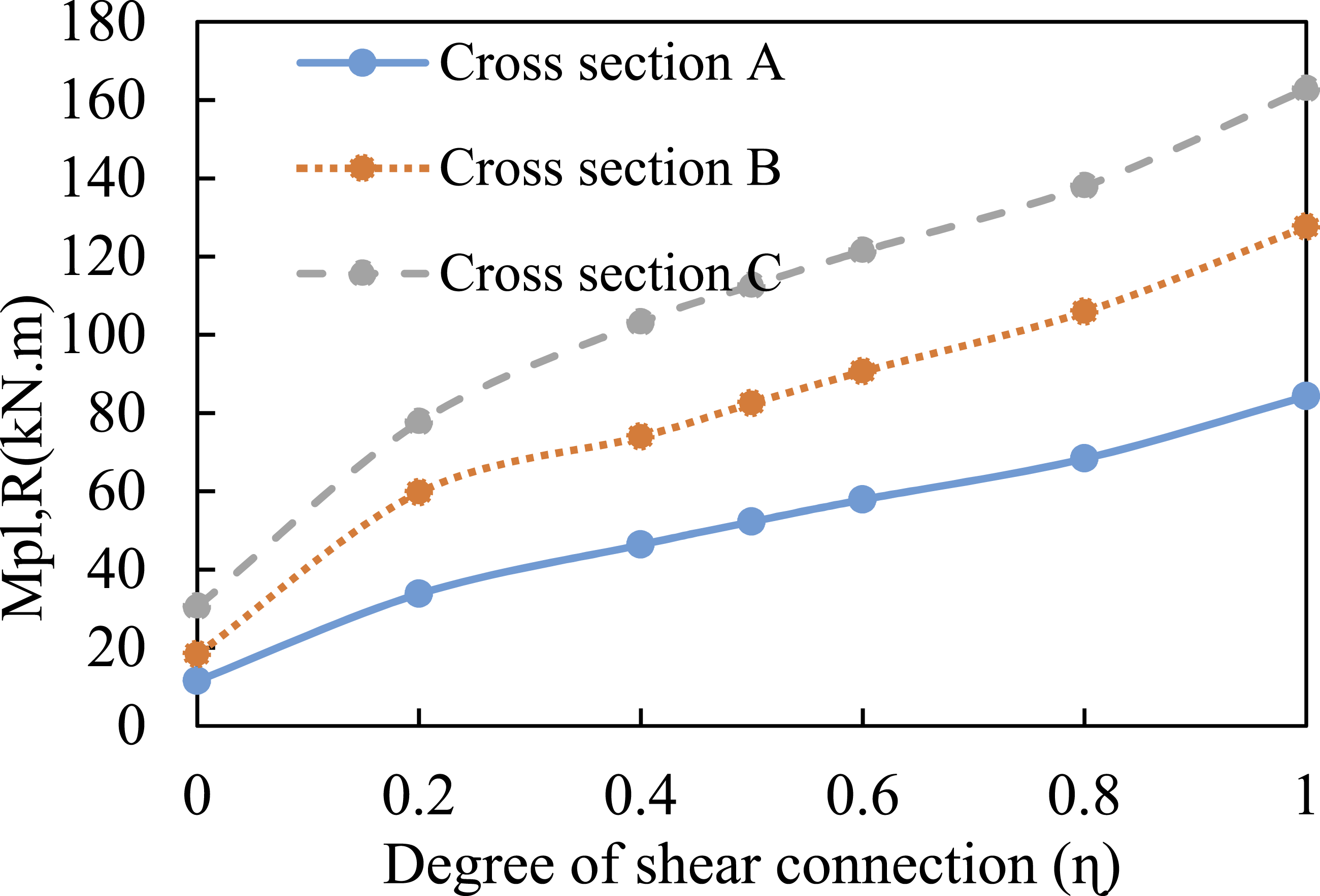
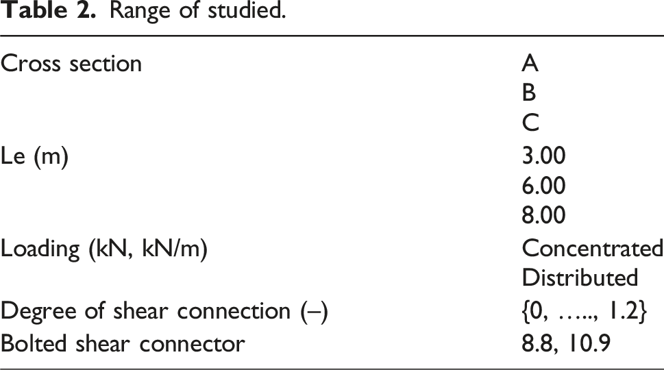
Figure 4 shows the profiled steel sheeting used, with a thickness of 0.8 mm. Dimensions of profiled steel sheeting.
Experimental study
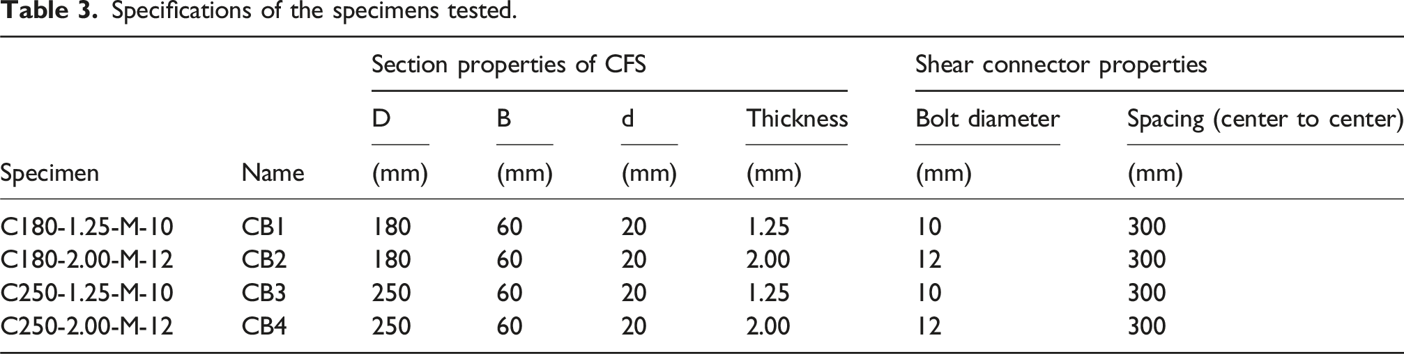
Specifications of the specimens tested.

Components of composite beams and their geometry.
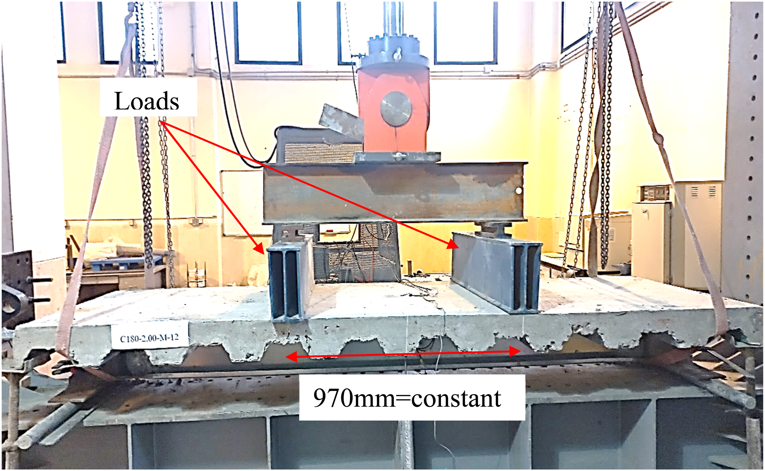
Loading and configuration of experimental beams.
Finite element modeling
In this study, a numerical model was developed and validated against experimental results detailed in Karimipanah et al. (2024a). ABAQUS software (ABAQUS, 2020) was used for modeling and three-dimensional FE analysis. The model setup is described as follows.
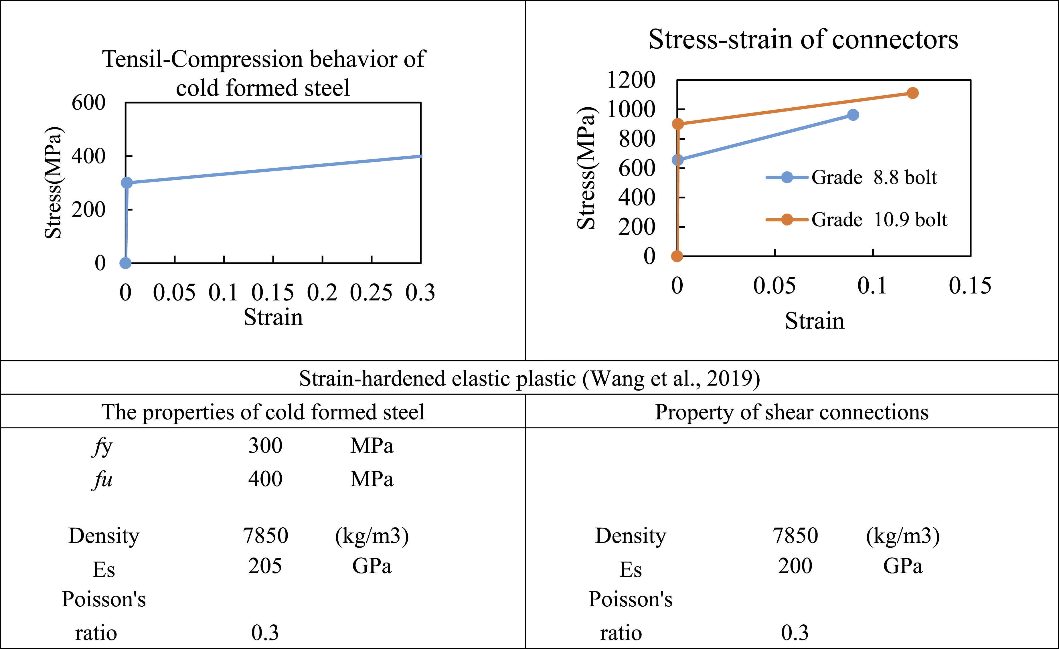
As shown in Figure 7, in the FE model of the specimens, modeling the sheet and CFS beam was considered using a four-node 3D shell element, S4R. Concrete slabs and high-strength steel bolts as shear connectors were also modeled with a three-dimensional solid element C3D8R with eight nodes. FE models for concrete slabs did not include reinforcement due to their low stress level. Figures 8 and 9 show the modeling of all composite beam components and FE-modeling parameters. Based on experimental load-displacement data, a displacement-control loading regime was applied to the model in this study. There was excellent agreement between specimens and their FEM models for load versus mid-span deflection curves and failure modes. ABAQUS modeling of composite beams. Modeling of concrete and parameters in FE-modeling. Modeling of steel components and parameters in FE-modeling.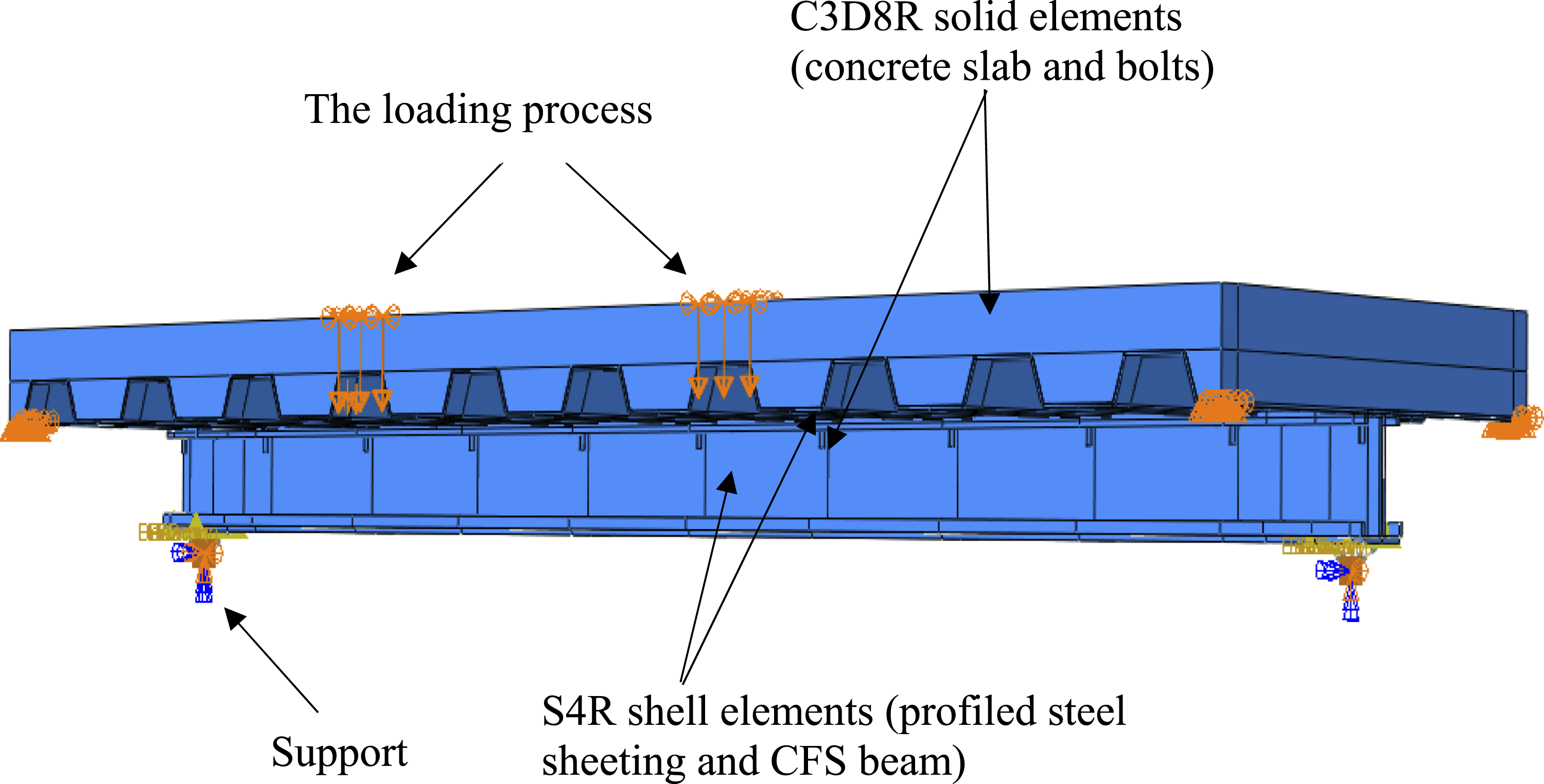

Parametric study on the minimum degree of shear connection
FE-parametric studies are described using the validated FE model described in the previous section. An illustration of this parametric study can be found in Table 2, and using their results, the minimum degree of shear connection ηmin is calculated. For example, Figure 10 depicts the diagram of moment-displacement of specimens A-C in ηmin ≈ 0.5 in the middle of the composite beam’s span. Response of moment-displacement of specimens A-C in ηmin ≈ 0.5 using FE-modeling.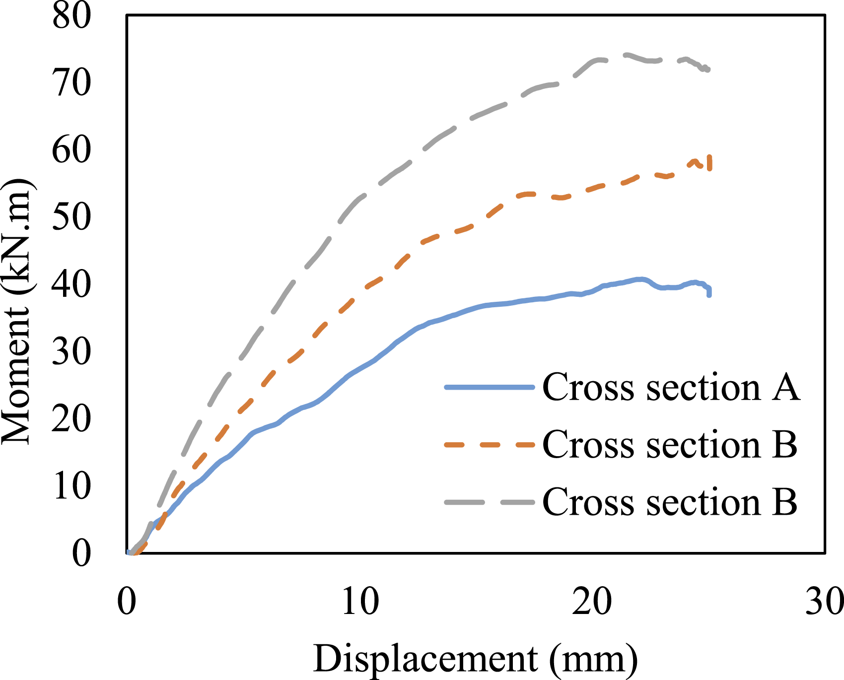
Exemplary determination of ηmin
The beam end slip can result in unsafe results because the maximum slip is variable at the steel-concrete interface. In fact, when the steel beam’s yield strength is exceeded, the maximum slip may move away from the beam’s end and toward the yielding area. Therefore, in the following sections, only the second method (see the Partial Shear Connection section, Method 2) is used to compare flexural strengths as determined by FE and bending resistance as determined by equilibrium. In this study, the degree of shear connection is controlled by the number of shear connectors, as well for greater shear connection degrees, their diameters are changed.
Influence of the load configuration
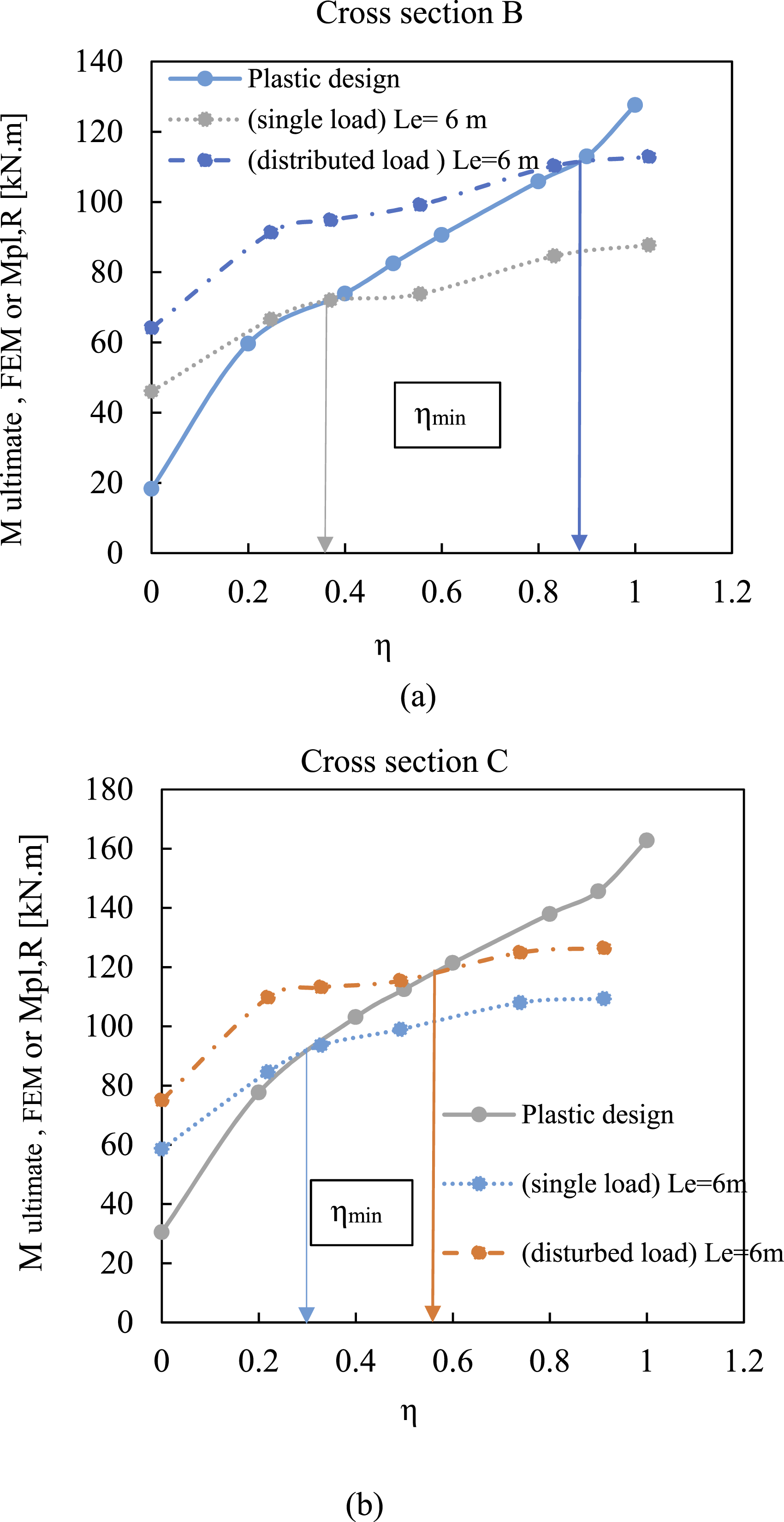
Figure 11 shows different types of loading that were considered in this study. Figure 12 illustrates how the minimum degree of shear connection is affected by load configuration. When a concentrated load at mid-span is applied to a composite beam, the ηmin values are substantially smaller than for beams with uniform loads. Because the shear connectors at the interface of steel-concrete are spaced evenly, a constant shear flow develops in the interface for a load with a constant distance at mid-span and usually elastic shear flow is also matched by them. Thus, shear forces don’t redistribute, and ηmin values are relatively small. Since composite beams with uniform load do not have uniform shear distribution in the connectors and have significant shear at the ends, the shear needs to be transferred to other intermediate connectors. It is obvious that composite beams with uniform load yield significantly higher ηmin values due to the inelastic redistribution of shear forces within the steel-concrete interface. Simulation of composite beams under different loading conditions: (a) single (b) disturbed. Minimum degree of shear connection for a span with cross-sections B and C.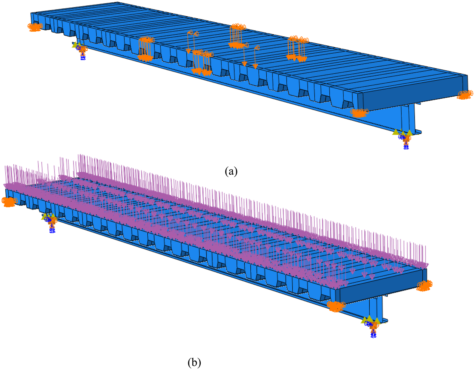
Influence of beam span (Le sagging bending distance)
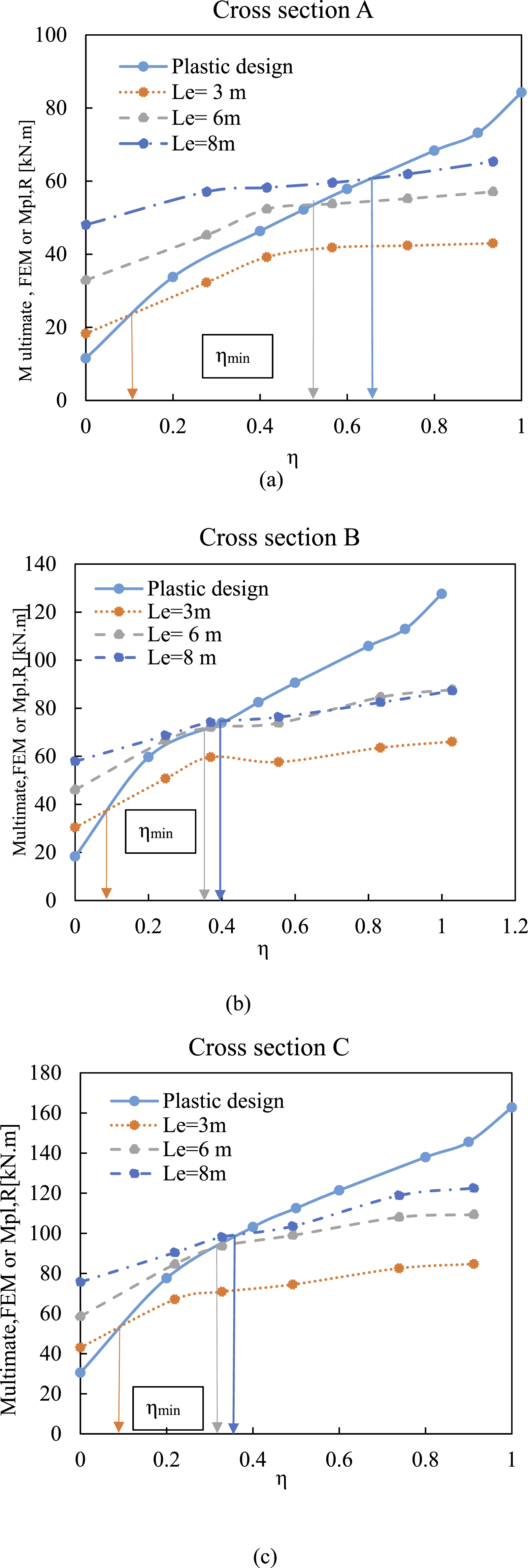
In this study the effect of the span Le on ηmin for all sections (A-C) is investigated. So, ηmin was evaluated for a beam span of 3, 6, and 8 m (Figure 13), as shown in Figure 14. Composite beams exhibit greater slip deformations at the steel-concrete interface when the span Le (the distance between points at which there is no bending moment) is increased. Therefore, when no change has been made to the connectors’ deformation capacity, deformations due to increased slip result in higher values of ηmin. Different span lengths for composite beams. (a)−3 (b)−6 (c)−8 m. Minimum degree of shear connection for different spans in cross-sections A to C.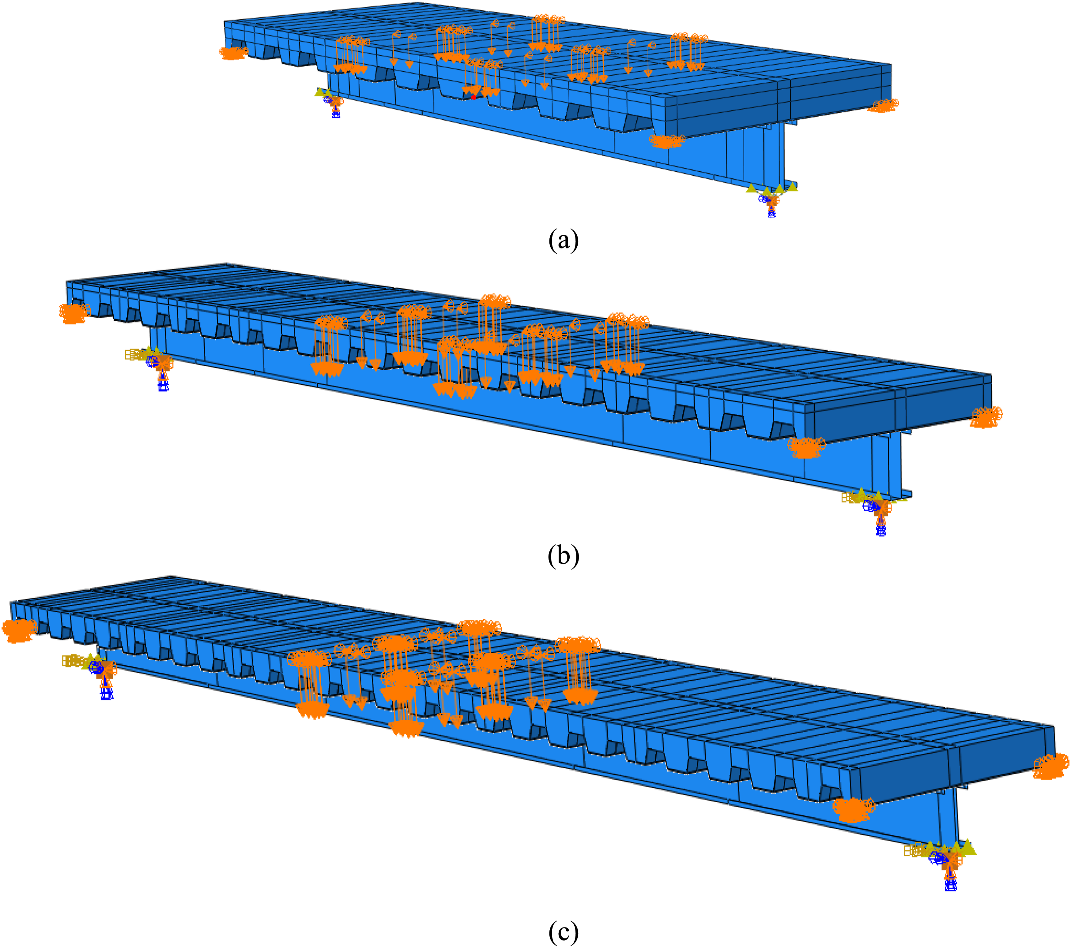
Influence of cross-section geometry
Figure 14 shows how the minimum degree of shear connection depends on the beam’s cross-sectional geometry. As mentioned earlier, by calculating the ratio between the plastic bending resistance of the steel section Mpl,bare and that of the composite section with full shear connection Mpl,R,FSC (ratio Mpl,bare/Mpl,R,FSC), composite cross-section geometries can be classified. In Figure 14, by comparison for ηmin between cross-section A with Mpl,bare/Mpl,R,FSC = 0.25 to section C with Mpl,bare/Mpl,R,FSC = 0.37, it can be found that the values for section C are significantly lower than those for section A when all other conditions are the same (identical beam span and deformation characteristics of the connectors). This can also be seen in Figure 12. With higher Mpl,bare/Mpl,R,FSC values, slip deformations at the steel-concrete interface are decreased, and fewer connectors are required. This is in agreement with the results of other researchers (Classen, 2018).
Steel grade of shear connections
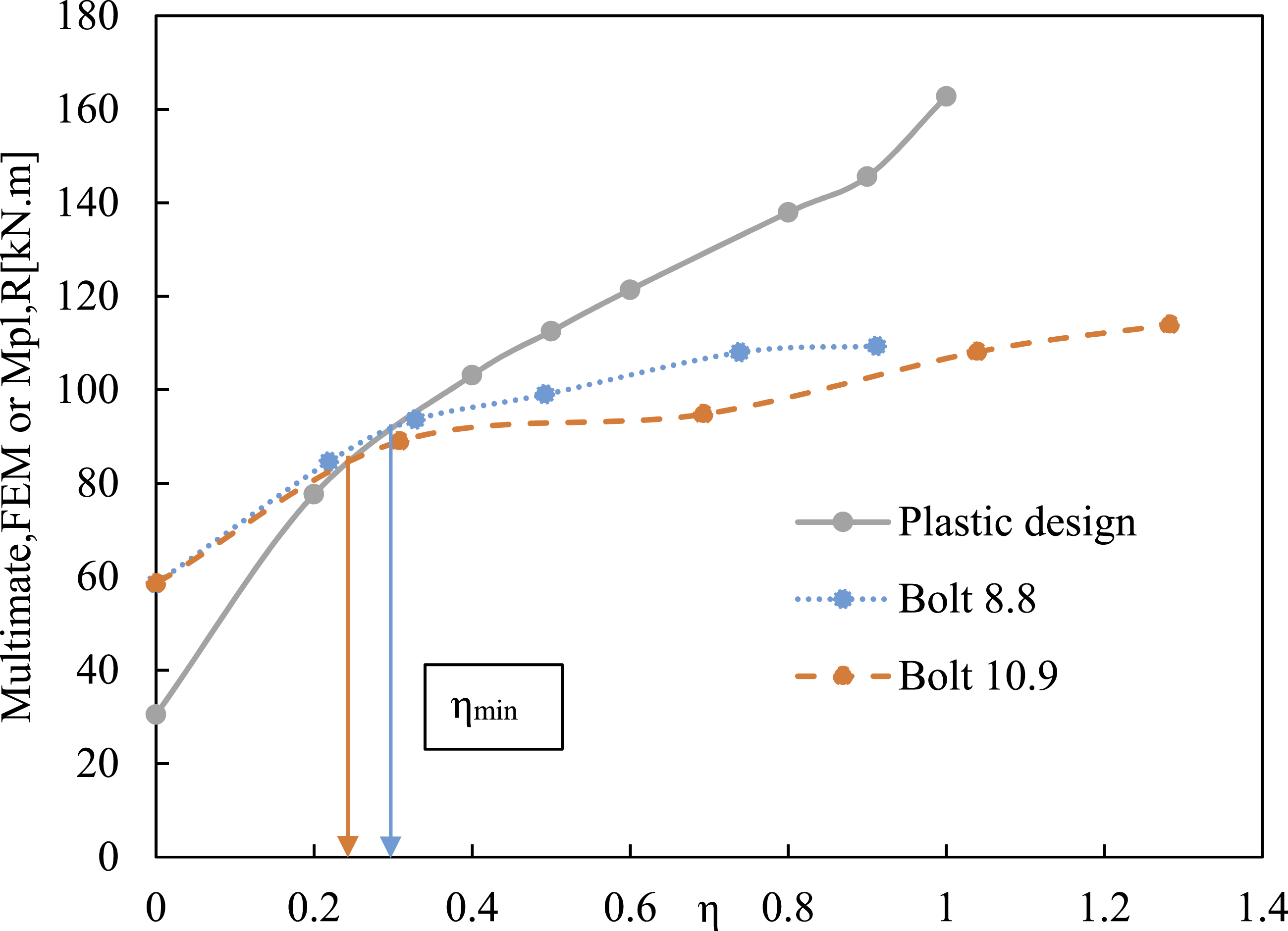
In this study, only 8.8 bolted shear connectors were considered because of the better performance. This type of shear connector with a deformation capacity larger than 6 mm according to EC4 code is ductile (Hosseinpour et al., 2021). A parametric study was conducted to illustrate the effect of steel grade of shear connection (ductility and deformation capacity) on a beam with 3 and 6 m span and cross-section C and different shear connection characteristics (8.8 to 10.9). As shown in Figures 15 and 16, increasing the minimum degree of shear connection ηmin occurred with decreasing deformation capacity. Shear connectors with greater ductility and deformability can better redistribute shear forces over the steel-concrete interface, according to Classen (2018). As a result, the ηmin limitations determined for beams with brittle connectors are conservative when applied to beams with more ductile connectors. Minimum degree of shear connection for different shear connections in cross-sections C, span 3 m. Minimum degree of shear connection for different shear connections in cross-sections C, span 6 m.
Proposed design model
This section presents engineering models derived from the FE-parametric study results (Section Minimum degree of shear connection (ηmin) for cross sections A-C in different spans.





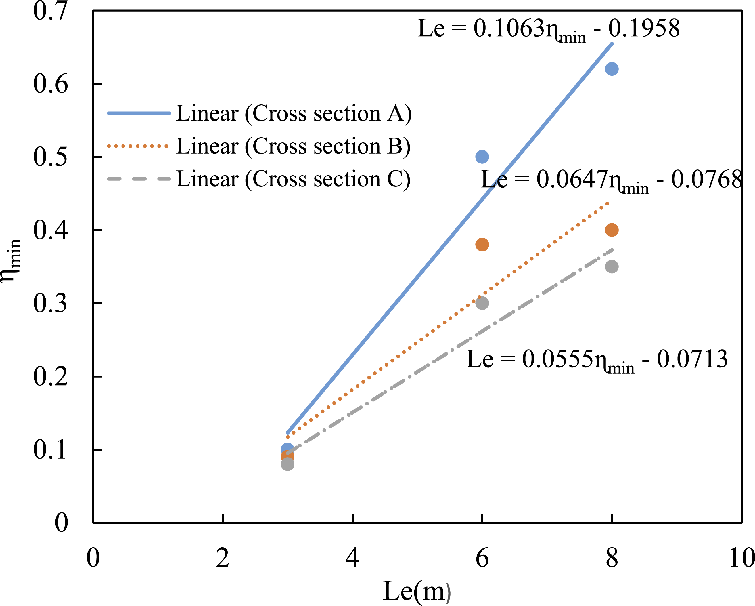
Considering that these functions were derived for 8.8 bolts as shear connectors, they are conservative for shear connectors with higher deformation capacities such as 10.9 bolts. Although some parameters, including concrete strength f'c and steel strength f y remained constant in this research, additional parameters should be investigated in the future study for a comprehensive function.
Conclusion
In this study, limitations of the use of partial shear connection in cold-formed composite beams with profiled steel sheeting were investigated. Several parameters influence the flexural strength and a minimum degree of partial shear connection of composite beams, including loading configuration (uniformly distributed load vs concentrated load), beam span (Le), connector deformation capability, and geometry of steel and composite sections. In summary, the following findings are noteworthy: • Under uniformly distributed loads, composite beams require significantly more degrees of shear connection than beams with concentrated loads at midspan (approximately two times). • For disturbed loads, the engineering models presented in this paper should be twice as large as those for concentrated loads. • Using FE-parametric analysis, linear functions were used to approximate the relationship between beam span and minimum degree of shear connection. • Only the parametric study was considered spans up to 8 m and the proposed engineering model is valid for this range. • Only 8.8 bolted shear connectors were considered in this study due to their superior performance. Using shear connectors such as 10.9 bolts with greater ductility and deformability can better redistribute shear forces over the steel-concrete interface and the ηmin limitations suggested are conservative. • By calculating the ratio between the plastic bending resistance of the steel section Mpl,bare and that of the composite section with full shear connection Mpl,R,FSC (ratio Mpl,bare/Mpl,R,FSC), composite cross-section geometries can be classified. A comparison for ηmin is made between cross-section A with Mpl,bare/Mpl,R,FSC = 0.25 to section C with Mpl,bare/Mpl,R,FSC = 0.37. The values of ηmin for section C are significantly lower than those for section B when all other conditions are the same (no difference in the beam’s span or the connectors’ deformation characteristics). • Increasing the composite beam span means higher ηmin values are obtained due to greater slip deformations at the steel-concrete interface.
Footnotes

Funding
The authors received no financial support for the research, authorship, and/or publication of this article.
Declaration of conflicting interests
The authors declared no potential conflicts of interest with respect to the research, authorship, and/or publication of this article.