



Abstract
This paper presents an experimental and numerical investigation into the fire performance of reinforced concrete (RC) beams strengthened with externally bonded carbon fiber-reinforced polymer (CFRP) sheets and protected by various anchorage and insulation systems. Seven full-scale beams were tested, including three specimens under ambient conditions and four exposed to the ISO 834 standard fire curve. The key parameters examined included insulation schemes, such as a 20 mm cement-based fire-resistant plaster (SJ-2) and a hybrid system combining 2 mm intumescent coating with a 20 mm mortar or SJ-2 layer, as well as the anchorage configurations including mechanical anchors and CFRP U-wraps. Experimental results showed that all insulated specimens achieved a fire-resistance rating of at least 2.5 hours without failure. The combined application of insulation and anchorage systems effectively reduced midspan deflections during fire exposure, primarily by preserving the tensile contribution of the CFRP sheets. A coupled thermal-mechanical numerical model was developed by integrating transient heat transfer analysis with a fiber-based sectional approach. This model explicitly accounted for the temperature-dependent degradation of concrete, steel reinforcement and CFRP sheets. Numerical predictions closely aligned with the experimental results, which accurately predicted the temperature distributions across the beam cross-sections and the degradation of flexural capacity. The validated model serves as a reliable tool for simulating the fire response of CFRP-strengthened RC beams with various anchorage and insulation systems, thereby offering a basis for optimizing fire protection designs and providing a reference for engineering practice in enhancing fire resistance using anchorage systems.
Keywords
Introduction
Fiber-reinforced polymer (FRP) laminates, including wet layup sheets and pultruded plates, are increasingly employed for the strengthening and rehabilitation of reinforced concrete (RC) structures. Their high strength-to-weight ratio, superior corrosion resistance, ease of installation and minimal impact on structural geometry make them highly advantageous in civil engineering applications (Gong et al., 2024; Hollaway and Teng, 2008; Yang et al., 2025). However, when utilized in building applications, externally bonded (EB) FRP systems must meet the fire-resistance requirements stipulated by relevant design codes. This presents a significant challenge, as the polymeric matrix and adhesive (typically epoxy resins) in FRP systems exhibit relatively low glass transition temperatures (T g ), which is typically ranging from 45°C to 80°C (ACI 440.2R, 2017; fib Bulletin 14, 2001). At elevated temperatures near or exceeding this threshold, the bond strength and mechanical properties of FRP strengthening systems degrade rapidly (Dai et al., 2013; Dong et al., 2022; Gao et al., 2012, 2015a; Guo et al., 2021, 2023a, 2023b; Lu and Xian, 2017; Tam et al., 2019; Wang et al., 2018; Zhou et al., 2020, 2022). In the absence of sufficient fire protection, EB FRP laminates are also susceptible to ignition. Consequently, effective fire insulation is essential to ensure that FRP-strengthened RC members achieve the required fire-resistance ratings (Deng et al., 2025; Lau et al., 2016; Zhang et al., 2018).
The fire performance of FRP-strengthened RC members is often evaluated through full-scale fire tests. Previous studies have investigated the effects of insulation type, thickness, configuration, heating conditions and boundary restraints on the fire resistance of FRP-strengthened RC beams (Adelzadeh et al., 2012; Ahmed and Kodur, 2011a; Blontrock et al., 2000; Dong et al., 2023; Firmo and Correia, 2015; Gao et al., 2010; Williams et al., 2008). These investigations have demonstrated that appropriate insulation can enable FRP-strengthened RC beams to achieve satisfactory fire resistance while highlighting the pronounced sensitivity of thermal and structural responses to various design parameters. Several numerical models have been developed as alternatives to full-scale fire testing to simulate the fire behavior of insulated FRP-strengthened RC beams (Ahmed and Kodur, 2011b; Dai et al., 2015; Firmo et al., 2014, 2018; Gao et al., 2013, 2016, 2017; Hawileh et al., 2009). For example, Dai et al. (2015) proposed a three-dimensional finite element (FE) model incorporating local bond-slip constitutive laws between reinforcing steel, FRP laminates and concrete at elevated temperatures. This FE model demonstrated good agreement with experimental fire tests (Blontrock et al., 2000; Gao et al., 2010; Williams et al., 2008). Some FE models have also been developed with considerations of the bond performance between the interfaces of the internal steel bars, the EB FRP strengthening systems and the concrete substrate at high temperatures, which yielded accurate failure model predictions for the EB FRP-strengthened RC beams under fire exposure (Ahmed and Kodur, 2011b; Dai et al., 2015; Firmo et al., 2014, 2018; Gao et al., 2013; Xiao et al., 2014, 2016). More recently, Gao et al. (2018a) proposed a three-level, performance-based framework for evaluating the fire resistance of FRP-strengthened RC beams, which has since been incorporated into the Chinese technical standard (GB 50608, 2020). However, both this framework and current design guidelines (ACI 440.2R, 2017; GB 50608, 2020) typically overlook the potential load-carrying contribution of EB FRP during fire exposure, unless a quite thick insulation layer (e.g., 70 mm coatings) is applied.
Recent studies suggest that anchorage systems can enhance the fire performance of insulated FRP-strengthened RC beams. Gao et al. (2010) demonstrated that extending EB carbon FRP (CFRP) sheets beyond the fire-exposed span, in combination with U-wraps in the anchorage zones, significantly improved the fire resistance of the insulated beams by preserving bond integrity between the CFRP sheets and concrete in cooler anchorage regions. This arrangement allowed the EB CFRP to continue functioning as effective tensile reinforcement during heating, acting similarly to a cable that sustains tensile force with both ends secured. Similar findings have been reported by Ahmed and Kodur (2011a) and Firmo et al., (2014). However, extending anchorage systems beyond the fire-exposed span is often impractical in real-world structures, as EB FRP sheets cannot traverse beam-column joints. This limitation has received limited attention in previous fire tests (Ahmed and Kodur, 2011a; Firmo et al., 2014; Gao et al., 2010), creating a significant gap in understanding the role of anchorage systems in the fire performance of insulated FRP-strengthened RC beams.
This study aims to address this gap through an experimental and numerical investigation into the fire performance of insulated RC beams strengthened with CFRP sheets. The experimental program systematically examines the effects of various insulation schemes and anchorage systems, including mechanical anchors (MA) and CFRP U-wraps (UW), on the fire resistance of insulated CFRP-strengthened RC beams. Particular focus is placed on assessing the contribution of EB CFRP sheets engaged by the anchorage systems during fire exposure. A coupled thermal-mechanical numerical model is developed by integrating transient heat transfer analysis with a fiber-based sectional approach to predict temperature distributions and flexural strength degradation throughout the heating process. This model explicitly incorporates the temperature-dependent properties of concrete, steel reinforcement, and CFRP sheets, enabling a quantitative evaluation of their contributions to the overall flexural capacity. Comparisons between the numerical and experimental results have confirmed the predictive accuracy of the numerical model and highlight the critical influence of anchorage systems on the residual flexural strength and fire resistance of insulated CFRP-strengthened RC beams.
Experimental program
Specimens preparation
Seven full-scale rectangular RC beams were constructed and tested in this study. Three beams were evaluated under ambient temperature conditions to establish baseline flexural behavior, while the remaining four specimens were exposed to fire following the ISO 834 standard fire curve. Each beam had a length of 6000 mm and a cross-sectional dimension of 250 mm (width) × 450 mm (depth). These dimensions were chosen to accommodate the horizontal furnace chamber (4500 mm long × 3000 mm wide). During fire testing, the beams were simply supported on metal rollers placed along the furnace walls, resulting in a clear span of 5200 mm. Longitudinal reinforcement consisted of three 20 mm diameter ribbed steel bars as the tensile reinforcement and two 14 mm diameter ribbed steel bars as the compressive reinforcement. Shear reinforcement was provided by 8 mm diameter stirrups spaced at 200 mm intervals. The geometric configuration and reinforcement details are shown in Figure 1. Details of the geometry, steel reinforcements and CFRP sheets (unit: mm).
The beams were cast using ready-mixed concrete with a target compressive strength of 30 MPa. The concrete mix included 224 kg of cement, 69 kg of mineral powder, 64 kg of fly ash, 1052 kg of coarse aggregate, 762 kg of fine aggregate, 175 kg of water and 4.28 kg of water-reducing agent per cubic meter. After a 28-day curing period, the average measured compressive strength was 37.0 MPa with a standard deviation of 1.3 MPa, while at the time of fire testing, the concrete compressive strength was 37.3 MPa with a deviation of 1.5 MPa; both were determined from three 150 mm cubes, respectively. The moisture content of the concrete at the time of fire testing was approximately 4.1%. Tensile testing of the steel reinforcement revealed an average yield strength of 445 MPa and an ultimate strength of 605 MPa with standard deviations of 7.2 MPa and 10.0 MPa for the main bars, and 353 MPa and 555 MPa with standard deviations of 5.4 MPa and 8.9 MPa for the stirrups. The elastic moduli for concrete and steel were 32.8 GPa and 204 GPa, respectively.
After approximately 3 months of curing, the RC beams were strengthened with CFRP sheets using the wet lay-up technique. The central 4400 mm region of each beam, which corresponds to the fire-exposed area, was retrofitted with two layers of high-strength unidirectional carbon fiber fabric (Forrisio-CF30), each providing an equivalent fiber thickness of 0.167 mm. The fabric was impregnated with a compatible epoxy adhesive (Forrisio-CFA). Prior to CFRP application, the beam soffits were roughened using sandblasting to expose the coarse aggregate, followed by cleaning and the application of an epoxy primer. The CFRP sheets were then cut to size, saturated with resin, and aligned longitudinally along the beam span. A final resin layer was applied to ensure complete encapsulation, and fine quartz sand was sprinkled over the surface to improve the bond between the CFRP and subsequent insulation layers.
Properties of CFRP sheets and epoxy resin.

Anchorage systems
Details of the specimens.

Note. The specimens are labeled as the format “Anchorage type-midspan insulation-anchorage zone insulation”. For the specimens where the insulation scheme is uniform across the entire fire-exposed span (including both the midspan and anchorage zones), only a single insulation designation is used.
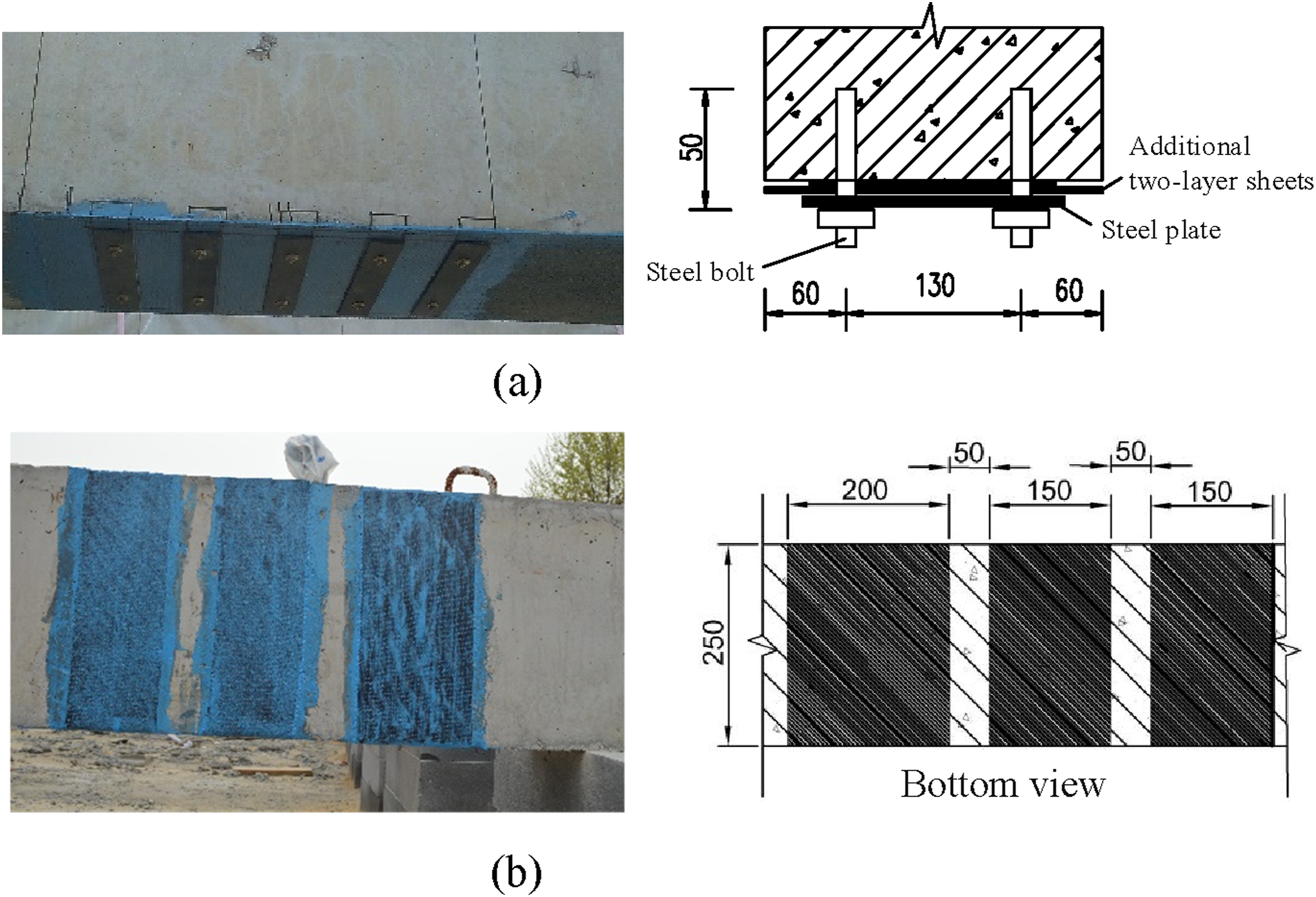
Details of different anchorage systems. (a) MA anchorage; (b) UW anchorage.
Fire insulation schemes
Three fire insulation schemes were applied to the central 4500 mm exposed span, which was subdivided into a central zone and two 500 mm anchorage zones, as shown in Figure 3. The first insulation material, designated SJ-2, consisted of a lightweight cementitious plaster manually applied to the surface of the structural component. The manufacturer specifications for this material at ambient temperature are as follows: dry density = 500 kg/m3, specific heat = 1000 J/(kg·K) and thermal conductivity = 0.120 W/(m·K). The second insulation material, Interchar-1120, is an intumescent coating with a dry density of 1560 kg/m3 and a specific heat of 800 J/(kg·K). The effective thermal conductivity of its fully developed char layer was estimated to be 0.0152 W/(m·K), based on the model proposed by Li et al. (2016). Additional details about the Interchar-1120 material can be found in Dong et al. (2023). The third insulation material was conventional cement mortar. The thermal properties of all insulation materials are summarized in Table 3. Layout of fire insulation scheme and thermocouple locations. (a) Layout of fire insulation scheme (unit: mm); (b) Locations of thermocouples. Thermal properties of insulation materials at ambient temperature.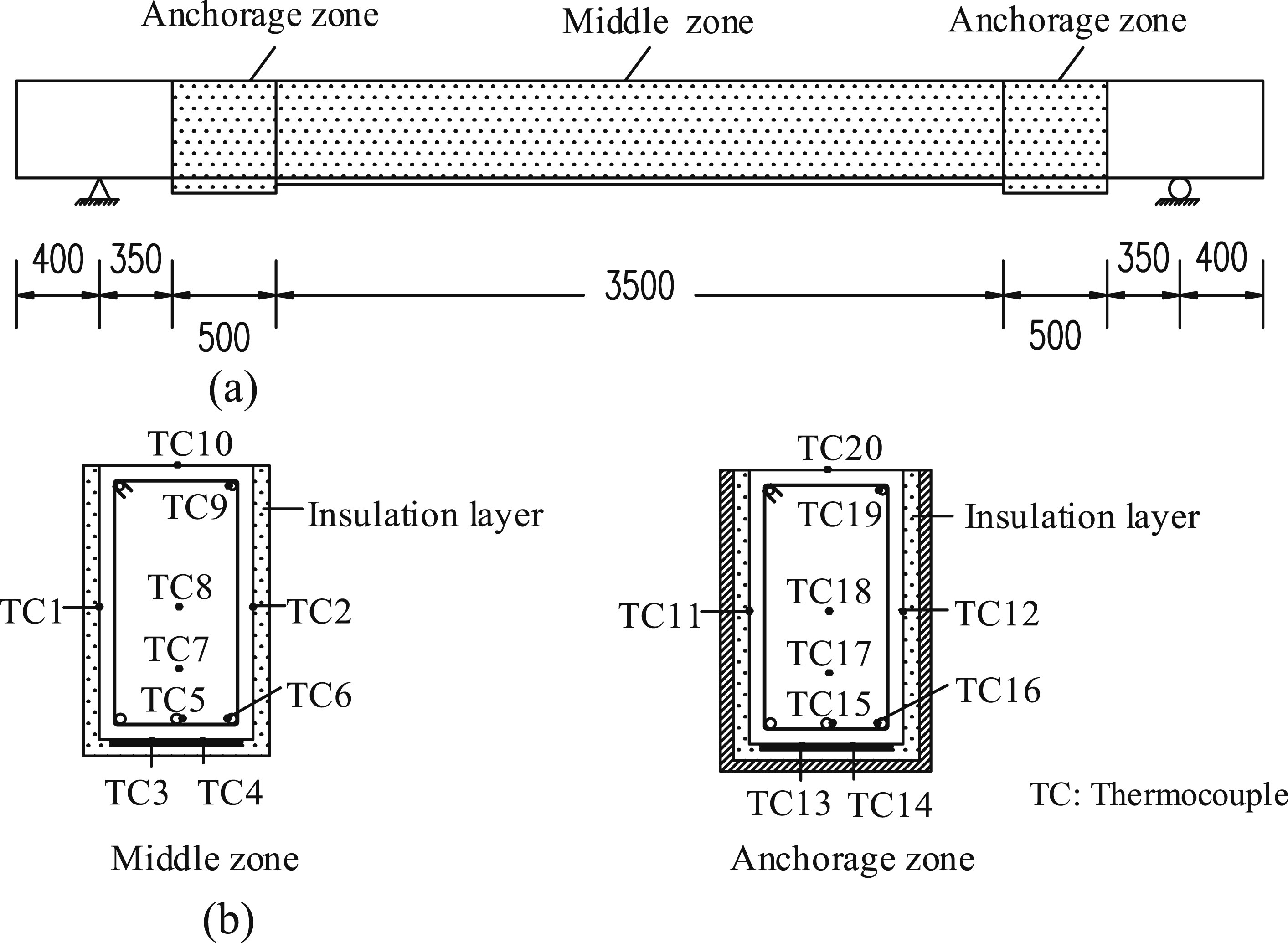

The specimens N-SJ2-SJ2IC and MA-SJ2-SJ2IC, which were designed to evaluate the MA anchorage system, received identical fire protection: the central region was insulated with a 20 mm layer of SJ-2, while the anchorage zones were protected by a hybrid system comprising 20 mm SJ-2 topped with a 2 mm layer of Interchar-1120. In contrast, the specimens UW-MortarIC and UW-SJ2, both employing UW anchorage, were subjected to different insulation schemes. The specimen UW-SJ2 was fully insulated with 20 mm SJ-2, while the specimen UW-MortarIC was protected with a 20 mm cement mortar layer finished with a 2 mm Interchar-1120 topcoat, which was expected to provide comparable fire protection.
Experimental setup and instrumentation
Ambient temperature testing
Three specimens were subjected to four-point bending tests at ambient temperature to establish their baseline load-carrying capacities. A monotonic loading protocol was employed, where a spreader beam applied two symmetrical point loads spaced 1500 mm apart (Figure 4). The structural response was monitored using a comprehensive instrumentation setup: strain gauges were affixed at midspan and within the shear spans to record the strain distribution in the EB CFRP sheets, while vertical displacements at midspan were measured using a linear variable differential transformer (LVDT). Data acquisition was conducted continuously at a sampling rate of 1 Hz. The testing procedure involved multiple loading stages: initially, a force-controlled loading manner was applied in 4 kN increments until the onset of concrete cracking. Subsequently, the loading rate was increased to 20 kN increments up to approximately 150 kN, followed by a displacement-controlled loading manner at 0.05 mm/s. Each load step was maintained for 3 minutes to allow for thorough documentation of crack patterns. The test was terminated upon observation of either CFRP debonding or tensile rupture of the strengthening system. Setup of the ambient temperature testing.
Fire testing
The fire tests were conducted in a horizontal furnace (Figure 5) with internal dimensions of 4.5 m × 3.0 m × 1.7 m, equipped with six natural gas burners capable of delivering a maximum output of 2.5 MW. Temperature control with the furnace were achieved in accordance with the ISO 834 standard fire curve using eight shielded thermocouples (Gao et al., 2018b). The fire tests were terminated when any of the following criteria were met: (1) structural failure, defined as either a midspan deflection greater than or equal to L/20, or a deflection rate exceeding L2/9000d (where L is the fire-exposed span and d is the beam depth) (ISO 834, 1999); (2) insulation failure, indicated by an average unexposed surface temperature rise of at least 140oC or a maximum point temperature rise of 180oC (ISO 834, 1999); or (3) the attainment of a tensile steel temperature of at least 593oC (corresponding to approximately a 50% reduction in yield strength) (EN 1992-1-1, 2004; Kodur and Ahmed, 2010). If none of these criteria were met, the fire tests were concluded at 2.5 hours, which corresponds to the maximum fire resistance rating for beams as specified in the Chinese code (GB 50016, 2014). Picture of the Series-I fire test.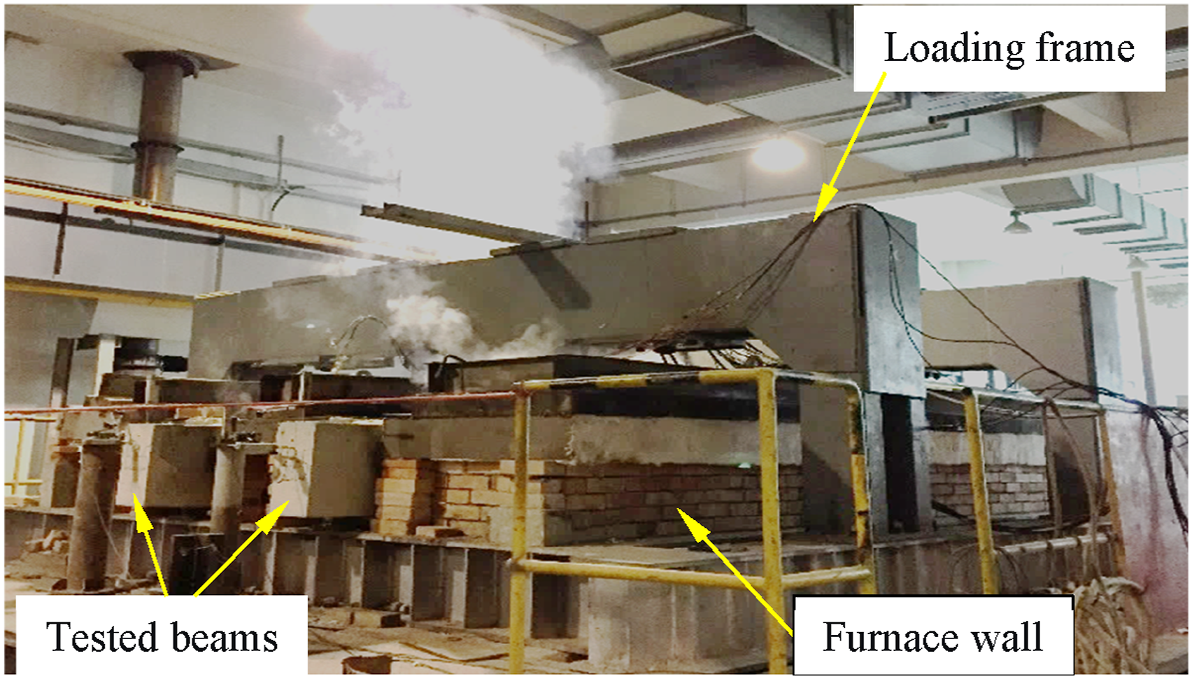
Aerated concrete blocks and rock wool blankets were used to fill the gaps between the beams and the furnace walls, thereby reducing heat loss and permitting free thermal deflections (Figure 5). Each fire test series involved two beams supported on steel rollers positioned on the furnace walls. The beams had a clear span of 5200 mm, with the central 4500 mm span exposed to fire. According to the ISO 834 test standard (ISO 834, 1999), the beams were exposed to fire from the bottom and both sides, while the top surface remained at ambient conditions. Throughout the fire tests, the beams were subjected to a service load corresponding to 57.6% of the ambient load-carrying capacity of the CFRP-strengthened RC beams. Such a load level represents a typical service load, which was determined as the sum of the self-weight and live load (both transferred from the adjacent slabs with a total width of 3.0 m) divided by the ambient load-carrying capacity of the CFRP-strengthened RC beams.
A total of 20 type-K chromium-nickel thermocouples (TCs) were installed at both the midspan and anchorage zone sections to monitor temperature profiles at various locations, including those within the concrete, steel reinforcement, CFRP–concrete interfaces, and insulation–concrete interfaces (Figure 3(b)). At the midspan zone, TC1 and TC2 were positioned at the CFRP-to-concrete interface on the beam soffit; TC3 and TC4 at the insulation-to-concrete interface at mid-depth; and TC5, TC6 and TC7 at the middle tensile rebar, corner tensile rebar, and corner compressive rebar, respectively. Additional thermocouples (TC8, TC9 and TC10) were embedded within the concrete at one-quarter depth, mid-depth, and on the unexposed top surface. Identical thermocouple arrangements were replicated in the anchorage zones using TCs 11–20, allowing for direct comparison of temperature responses. The adopted configuration yielded comprehensive temperature measurements at key interfaces and internal points, facilitating validation of the subsequent FE-based heat transfer analysis. A displacement transducer (NS-WY06 model with a 500 mm stroke) was affixed to the unexposed surface (top) of the beam to continuously record the midspan deflections throughout the fire exposure. Additionally, the beams were visually inspected through a small viewport in the furnace wall to document phenomena such as insulation cracking, CFRP ignition or delamination.
Test observations
Ambient temperature test
Beam N-0, serving as the unstrengthened reference specimen, exhibited a typical flexural failure mode characterized by compressive crushing of the top concrete near the loading point after yielding of the tensile steel reinforcement. This behavior confirmed the expected ductile flexural response of a properly designed RC beam under static loading. In contrast, the CFRP-strengthened specimens (MA-0 and UW-0), which utilized different anchorage systems, failed through intermediate crack (IC)-induced debonding of the CFRP sheets. Debonding initiated at major flexural cracks and propagated toward the ends of the CFRP sheets, consistent with failure modes commonly reported for FRP-strengthened RC members.
The load-deflection relationships of the three beams tested under ambient temperature conditions are shown in Figure 6. Prior to the initiation of concrete cracking, all the specimens exhibited nearly identical elastic stiffness, indicating that the EB CFRP sheets contributed minimally to the initial stiffness. Once significant flexural cracks formed at an applied load of approximately 100 kN, the post-cracking stiffness of the strengthened beams (MA-0 and UW-0) increased markedly compared with the unstrengthened reference specimen. Load-deflection curves of the beams tested at ambient temperature.
Between the two strengthened specimens, the beam MA-0, which was equipped with the MA anchorage, exhibited slightly higher stiffness and load-carrying capacity than UW-0, which utilized the UW anchorage. This improvement can be attributed to the enhanced anchorage efficiency of the MA system, which delayed complete CFRP debonding and promoted a more gradual load transfer, resulting in greater deformation capacity and a more ductile failure response.
Series-I fire test
During the initial 5 minutes of fire exposure, dense white smoke was observed emerging from the end regions of the beams within the furnace. This phenomenon, which persisted for approximately 30 minutes, indicated the activation and expansion of the Interchar-1120 intumescent coating. The expansion of the coating substantially increased the effective insulation thickness, thereby enhancing the overall thermal protection of the beam surfaces. At approximately 80 minutes of exposure, both specimens exhibited a pronounced increase in midspan deflection, which corresponded to the onset of bond degradation as the CFRP–concrete interface temperatures approached critical thresholds. Despite this, both beams maintained their structural integrity throughout the full 150-min fire duration. No signs of spalling or detachment of the insulation materials were observed, indicating the excellent cohesion and adhesion stability of the insulation materials under sustained high-temperature conditions.
Post-fire examination further confirmed that all insulation layers remained well adhered to the concrete substrate (Figure 7(a)). A few minor vertical cracks appeared along the side surfaces near the midspan regions, which can be attributed to thermal expansion and restrained deformation. After the insulation was removed, the anchorage zones were carefully inspected. The epoxy adhesive largely retained its original color and exhibited no visible delamination of the CFRP sheets (Figure 7(b)), confirming that the hybrid insulation system provided effective protection to the critical interface regions. Moreover, the MA anchorage system in MA-SJ2-SJ2IC remained intact with no observable damage (Figure 7(c)), demonstrating excellent thermal stability and mechanical integrity under elevated-temperature exposure. Post-fire conditions of the Series-I beams. (a) N-SJ2-SJ2IC after fire; (b) Anchorage zone of N-SJ2-SJ2IC; (c) MA anchorage of MA-SJ2-SJ2IC.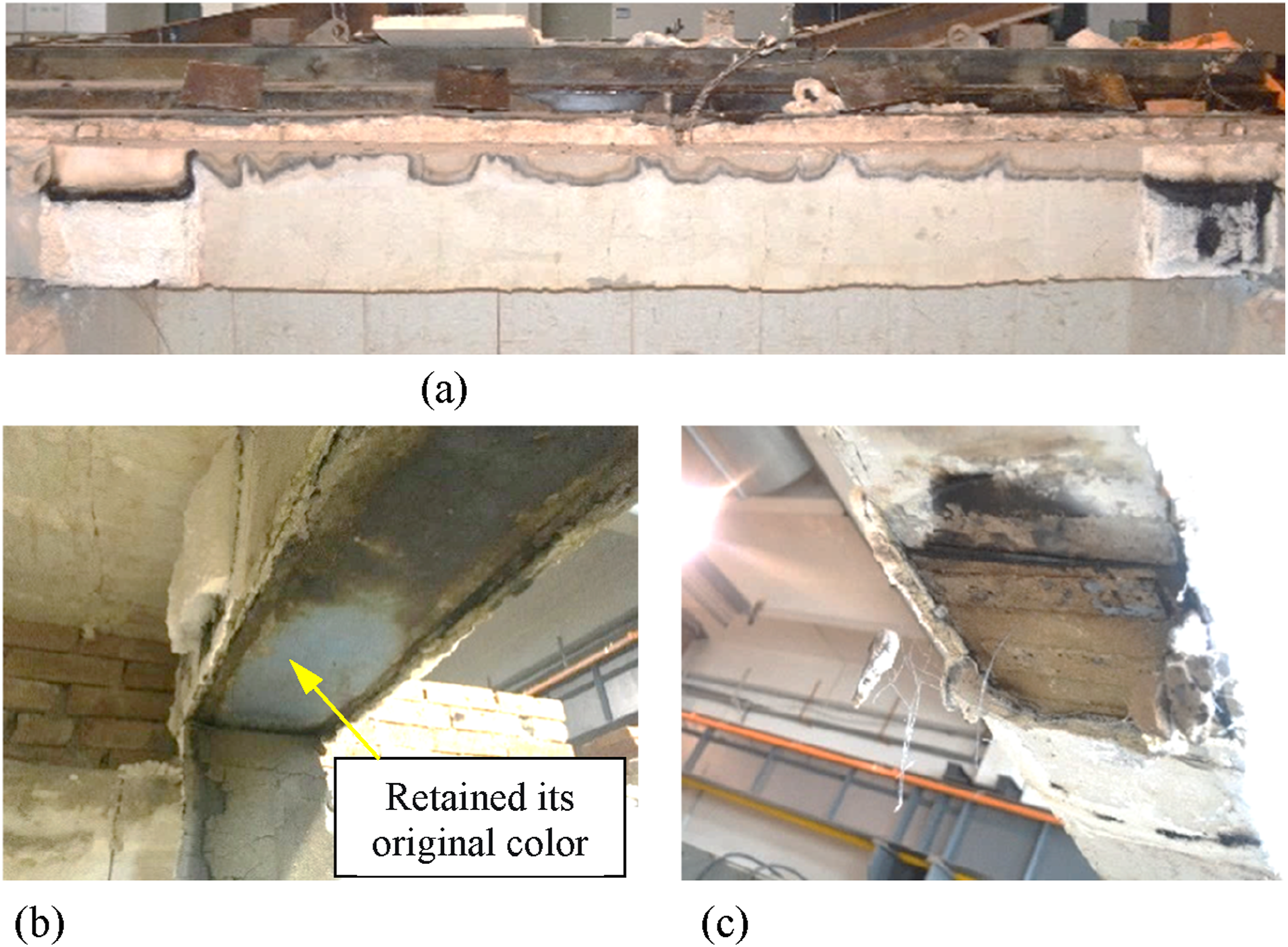
Series-II fire test
The Series-II fire tests (UW-MortarIC and UW-SJ2) exhibited similar early-stage smoke emission, indicating the activation and expansion of the intumescent coating layer. Both beams maintained their overall structural integrity throughout the 150-min exposure, and their insulation layers remained largely intact after testing (Figures 8(a) and (b)). However, localized delamination of the mortar layer was observed at the soffit of UW-MortarIC, suggesting potential limitations in the adhesion performance of conventional cement-based mortar when subjected to combined thermal and mechanical actions. Post-fire conditions of the Series-II beams. (a) UW-MortarIC after fire; (b) UW-SJ2 after fire; (c) UW anchorage of UW-MortarIC; (d) UW anchorage of UW-SJ2.
A detailed post-fire examination of the anchorage zones revealed more pronounced damage in the Series-II specimens compared with those in Series I. The UW anchorage systems in both Series-II beams exhibited partial carbonization (Figures 8(c) and (d)), indicating that their thermal protection was less effective than that of the hybrid insulation system used in Series I.
A comparative evaluation of the two insulation schemes in Series II offers further practical insights. The hybrid system consisting of a 20 mm mortar layer combined with a 2 mm Interchar-1120 (specimen UW-MortarIC) exhibited minor mortar delamination but provided satisfactory overall protection. In contrast, the SJ-2 fire-resistant plaster used in the specimen UW-SJ2 offered reasonable thermal insulation yet resulted in more severe CFRP damage within the anchorage regions. Overall, the fire tests confirmed that all insulation configurations achieved the target fire-resistance rating.
Results from fire tests
Temperature responses
The temperature evolution within the beam cross-sections provided critical insights into the thermal performance of different insulation configurations. Figure 9 presents the temperature-time histories recorded at multiple locations for the Series-I beams (N-SJ2-SJ2IC and MA-SJ2-SJ2IC). Owing to their identical insulation layouts, both specimens exhibited almost identical thermal responses. The maximum temperature measured at the concrete surface (i.e., the insulation–concrete interface) remained below 250°C throughout the 150-min exposure period. More importantly, after 2.5 hours of fire exposure, the temperatures of the corner and middle tensile steel rebars remained below 200°C and 160°C, respectively. These relatively low readings indicate the combined thermal protection provided by the insulation layer and the concrete cover, the latter of which served as an additional thermal barrier for the embedded reinforcement. Temperatures measured at various locations for the Series I beams. (a) Temperature responses at insulation/concrete and CFRP/concrete interfaces; (b) Temperature responses of tensile steel reinforcement.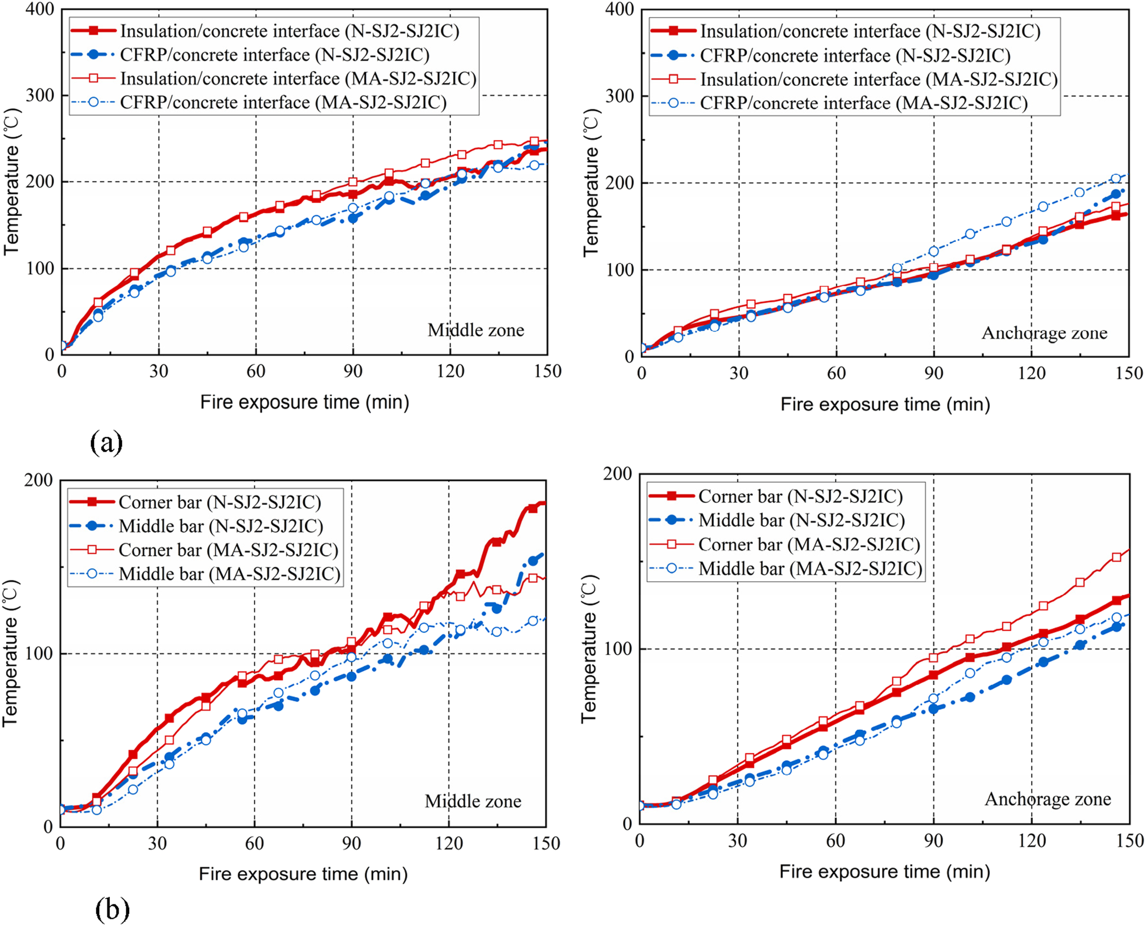
The thermal response in the anchorage zones was particularly critical for maintaining the overall structural integrity. These regions exhibited significantly lower temperatures than the central zone, primarily due to the additional protection offered by the Interchar-1120 intumescent coating. This temperature differentiation was instrumental in preserving the mechanical properties of both the steel reinforcement and the concrete during the fire tests.
Distinct thermal behavior was also observed at the CFRP–concrete interface. In the central zone, which was protected solely by a 20 mm SJ-2 plaster layer, the interface temperature reached the T g (T g = 71.7°C, determined at the tan δ peak) within approximately 20 minutes and subsequently rose to 200–250°C after 2.5 hours of exposure. These elevated temperatures indicated an almost complete loss of bond strength between the CFRP and the concrete substrate by the end of the fire test. In contrast, the hybrid insulation scheme (20 mm SJ-2 + 2 mm Interchar-1120) used in the anchorage zones maintained interface temperatures below T g for approximately 55 minutes, with a maximum interface temperature of only around 200°C after 2.5 hours. This result demonstrates that, although maintaining the interface temperature below T g solely by increasing insulation thickness is impractical, a well-designed combination of insulation and anchorage can effectively preserve the flexural contribution of EB CFRP sheets. This is achieved by enabling a cable action mechanism, where the EB CFRP sheets secured at both ends can continue to sustain tensile force, similar to a cable.
Figure 10 compares the thermal responses of the Series-II beams (UW-MortarIC and UW-SJ2), which exhibited distinctly different behaviors owing to their varied insulation schemes. Specimen UW-MortarIC, protected with a 20 mm cement mortar layer and 2 mm Interchar-1120, showed a rapid temperature rise to approximately 100°C within the first 25 minutes, followed by a pronounced temperature plateau lasting roughly 50 minutes. This plateau was attributed to moisture evaporation within the mortar layer, where latent heat absorption delayed further temperature increase. By contrast, the specimen UW-SJ2, insulated solely with 20 mm SJ-2 plaster, showed no such plateau, resulting in continuously rising temperatures throughout the exposure period. Temperatures measured at various locations for the Series II beams. (a) Temperature responses at insulation/concrete and CFRP/concrete interfaces; (b) Temperature responses of tensile steel reinforcement.
Despite localized delamination of the mortar layer in the specimen UW-MortarIC after approximately 90 minutes of exposure, the maximum interface temperature (310°C) remained lower than that in UW-SJ2 (341°C), confirming the superior thermal protection afforded by the hybrid system. However, both insulation schemes were only able to maintain the CFRP–concrete interface temperatures below T g for approximately 15–20 minutes.
The temperature histories of the tensile steel reinforcement further confirmed these observations. During the initial 10 minutes, both specimens exhibited negligible temperature increases in the steel bars. Beyond approximately 30 minutes, the corner rebars experienced slightly higher temperatures than the middle ones, as they were exposed to both bottom and side heating. Again, the hybrid insulation system demonstrated superior fire resistance: the specimen UW-MortarIC consistently maintained lower steel temperatures than UW-SJ2 throughout the majority of the test. The maximum corner rebar temperatures reached 248°C for UW-MortarIC and 232°C for UW-SJ2—both significantly below the critical temperature of 593°C, at which the yield strength of steel typically decreases by approximately 50%.
Midspan deflections
The time-deflection curves shown in Figure 11 provide a comprehensive representation of the structural behavior of the insulated CFRP-strengthened RC beams under sustained service loading during fire exposure. The deflection evolution can be categorized into five distinct stages, each associated with specific mechanical and thermal processes. Time-deflection responses of the tested beams. (a) N-SJ2-SJ2IC and MA-SJ2-SJ2IC; (b) UW-MortarIC and UW-S.
For the Series-I beams (N-SJ2-SJ2IC and MA-SJ2-SJ2IC), Stage I (0–8 min) exhibited negligible deflection changes, maintaining an approximately constant value of 20.8 mm. Stage II (8–25 min) was characterized by a rapid increase in deflection, primarily resulting from bond degradation at the CFRP–concrete interface in the central region. Stage III (25–30 min) represented a transitional phase with partially stabilized bond conditions; namely, complete debonding in the central zone (where temperatures exceeded T g +20°C) while partial adhesion was still preserved in the anchorage regions (temperatures below T g –20°C). Stage IV (30–56 min) involved further deflection growth as bond deterioration propagated toward the anchorage zones. Finally, Stage V (56–150 min) highlighted the critical influence of anchorage systems: the specimen N-SJ2-SJ2IC exhibited continuous deflection growth as the CFRP system became fully ineffective, whereas the specimen MA-SJ2-SJ2IC, equipped with a MA anchorage, showed smaller deflection increments due to the anchors restraining complete debonding and enabling a cable action to develop between the CFRP and the beam ends.
In contrast, the Series-II beams (UW-MortarIC and UW-SJ2) exhibited a distinct deflection evolution pattern resulting from the uniform insulation applied to both the central and anchorage zones. For the specimen UW-MortarIC, Stage I (0–5 min) showed minimal deflection changes, followed by Stage II (5–27 min), which involved a rapid deflection increase caused by simultaneous bond degradation along the beam span. Stage III (27–70 min) exhibited a pronounced deflection plateau, attributed to the combined effects of the insulation layer and the moisture evaporation within the mortar, which absorbed latent heat and delayed further heat penetration. During Stage IV (70–120 min), a gradual increase in deflection was observed as the CFRP system lost stiffness, despite the restraining action of the UW anchorage. Finally, Stage V (120–150 min) showed accelerated deflection growth driven by cumulative thermal expansion and progressive material degradation at elevated temperatures.
A comparative assessment of the different anchorage systems revealed pronounced behavioral differences. The specimen MA-SJ2-SJ2IC, equipped with the MA anchorage system, exhibited approximately 7% lower final deflection (51.3 mm) compared with the unanchored specimen N-SJ2-SJ2IC (55.3 mm). The specimens UW-MortarIC and UW-SJ2, both employing the UW anchorage system, showed even greater improvements, achieving final deflections of 40.7 mm and 41.6 mm, respectively, which represented reductions of approximately 20–26% relative to the unanchored reference beam. Among all configurations, the hybrid insulation system adopted in the specimen UW-MortarIC demonstrated the most favorable response, exhibiting the lowest final deflection and the slowest rate of deflection increase throughout the fire exposure. These results highlight the importance of combining a well-designed insulation layer with effective anchorage systems to enhance the overall fire performance and deformation control of CFRP-strengthened RC beams.
Numerical modeling
Heat transfer analysis
A coupled thermal-mechanical numerical framework was developed by integrating transient heat transfer analysis with a fiber-based sectional modeling approach. The transient thermal analysis was performed using the finite element (FE) software ABAQUS, with a model geometry identical to that of the tested beams (250 mm width, 450 mm depth and 4500 mm span), as illustrated in Figure 12. The insulation layers and concrete were modeled using 8-node continuum thermal elements (DC3D8), while the steel reinforcement was represented by 2-node link thermal elements (DC1D2). A mesh size of 10 × 10 × 10 mm was adopted based on a mesh sensitivity study, which achieved an optimal balance between computational efficiency and temperature prediction accuracy. Finite element model for transient heat transfer analysis.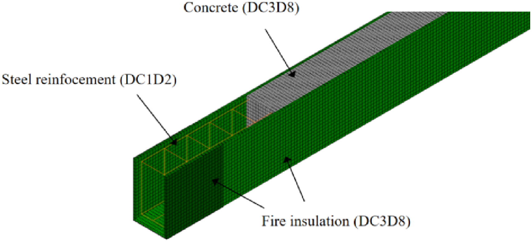
The temperature-dependent thermal properties of concrete and steel reinforcement were defined according to the previsions specified in EN 1992-1-2 (2004), which properly account for the temperature-dependent variations in thermal conductivity, specific heat and density of both materials at high temperatures. The thermal properties of the CFRP strengthening system were defined based on the recommendations provided in Dai et al. (2015). For the SJ-2 plaster and the Interchar-1120 intumescent coating, the thermal properties were defined as outlined in Section 2.3. For the conventional cement-based mortar, the following thermal properties were used based on the suggestions of Dong (2014): density = 1800 kg/m3, specific heat = 840 J/(kg·K), and thermal conductivity = 0.929 W/(m·K).
The thermal boundary conditions on the fire-exposed surfaces were defined by combining thermal convection and radiation effects. According to EN 1991-1-2 (2002), convection coefficients of 25 W/(m2·K) and 9 W/(m2·K) were applied to the exposed and unexposed surfaces, respectively, while an emissivity of 0.8 was assigned to the insulation layer. The transient heat transfer analysis employed an automatic time-increment procedure with a minimum time step of 0.2 minutes, as recommended by Gao et al. (2013), to ensure numerical stability and accurately capture the steep thermal gradients occurring during the early stages of standard fire exposure.
Comparisons with the measured temperatures
The validity of the FE model was verified through the detailed comparisons with the experimentally measured temperatures at multiple locations across the beam cross-sections. Figure 13 presents the predicted temperature distributions for the beams with different insulation schemes after 150 minutes of standard fire exposure. These results clearly exhibit the characteristic U-shaped isotherms that reflect the heat penetration from both the bottom and side surfaces. Due to the effective fire protection provided by the insulation layer, the maximum surface temperature of the concrete section at the corner was approximately 352°C. Cross-sectional temperature distributions for different insulation schemes. (a) 20 mm SJ-2 + 2 mm Interchar-1120; (b) 20 mm SJ-2; (c) 20 mm mortar + 2 mm Interchar-1120.
For the beams protected with the hybrid insulation system comprising 20 mm SJ-2 plaster and 2 mm Interchar-1120, Figure 14(a) and (b) show excellent agreement between the predicted and measured temperatures at both the insulation–concrete interfaces and the steel reinforcement locations. The model successfully captured the delayed temperature rise in the anchorage zones due to the enhanced protection from the intumescent coating, with maximum deviations remaining below 8% throughout the heating duration. Comparisons between precited and measured temperatures for the cross-sections protected with the hybrid insulation system comprising 20 mm SJ-2 and 2 mm Interchar-1120. (a) Interface temperature responses; (b) Steel bar temperature responses.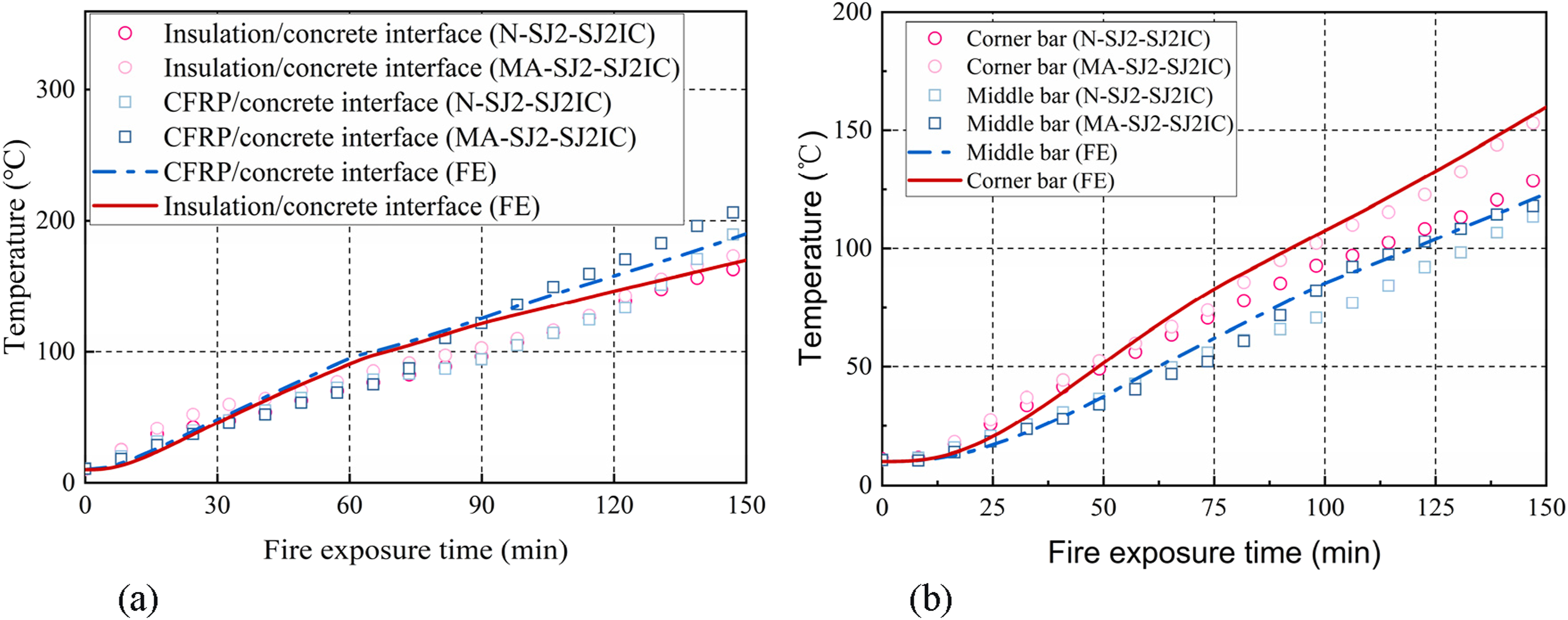
Similarly, for the specimen UW-MortarIC, which was insulated with 20 mm mortar and 2 mm Interchar-1120, Figure 15(a) and (b) show generally good correlation between the experimental and numerical results. However, the model slightly underestimated the temperatures during the intermediate heating stage (30–90 minutes). This deviation is attributed to the complex coupled effects of moisture migration and evaporation within the mortar layer, which were not explicitly modeled in the current heat transfer analysis. This discrepancy highlights a recognized limitation in the heat transfer analysis, as it does not explicitly account for transient moisture transport and phase change (i.e., heat absorption due to the moisture evaporation within the mortar insulation layer). Incorporating a coupled hygro-thermal analysis represents a potential area for future model refinement. Comparison between predicted and measured temperatures for the cross-sections protected with the hybrid insulation system comprising 20 mm mortar and 2 mm Interchar-1120. (a) Interface temperature responses; (b) Steel bar temperature responses. Note. “UW-MortarIC M” and “UW-MortarIC A” denote the thermocouple measurements at the midspan and anchorage zones, respectively.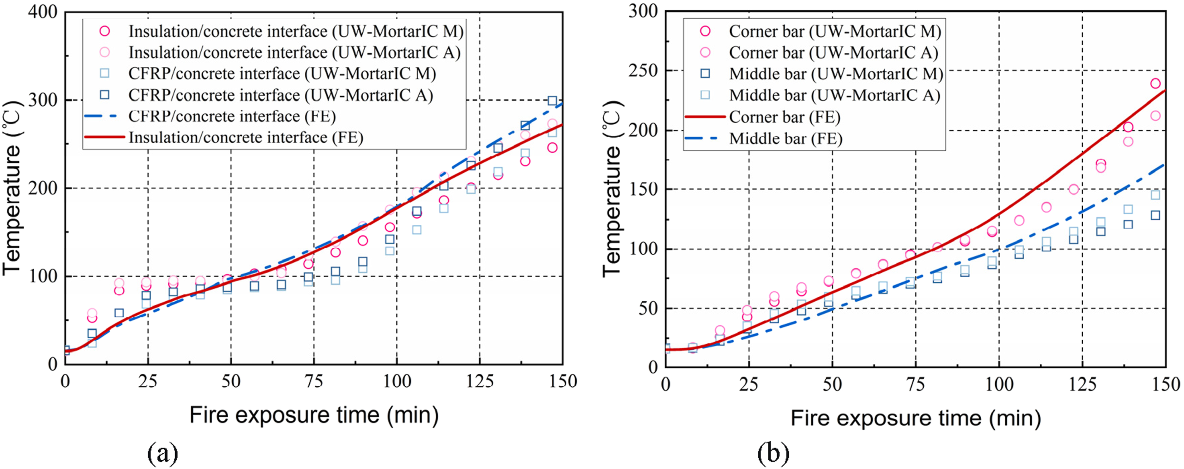
The validation of the specimen UW-SJ2 (Figure 16(a) and (b)) also demonstrated good agreement during the first series of fire tests. However, during the second series, the measured interface temperatures exceeded the predictions by approximately 10–15% during the later exposure stages. This discrepancy is likely due to partial carbonization of the UW anchorage system, which may have altered the local thermal properties near the interface. Overall, the FE model exhibited robust predictive capability for all insulation configurations, with the mean deviations between predicted and measured temperatures within 12% over the 150-min exposure period. This level of agreement is considered satisfactory for performance-based fire-resistance assessment and provides a reliable foundation for the subsequent mechanical response simulations. Comparison between predicted and measured temperatures for the cross-sections protected with a 20 mm SJ-2 layer. (a) Interface temperature responses; (b) Steel bar temperature responses.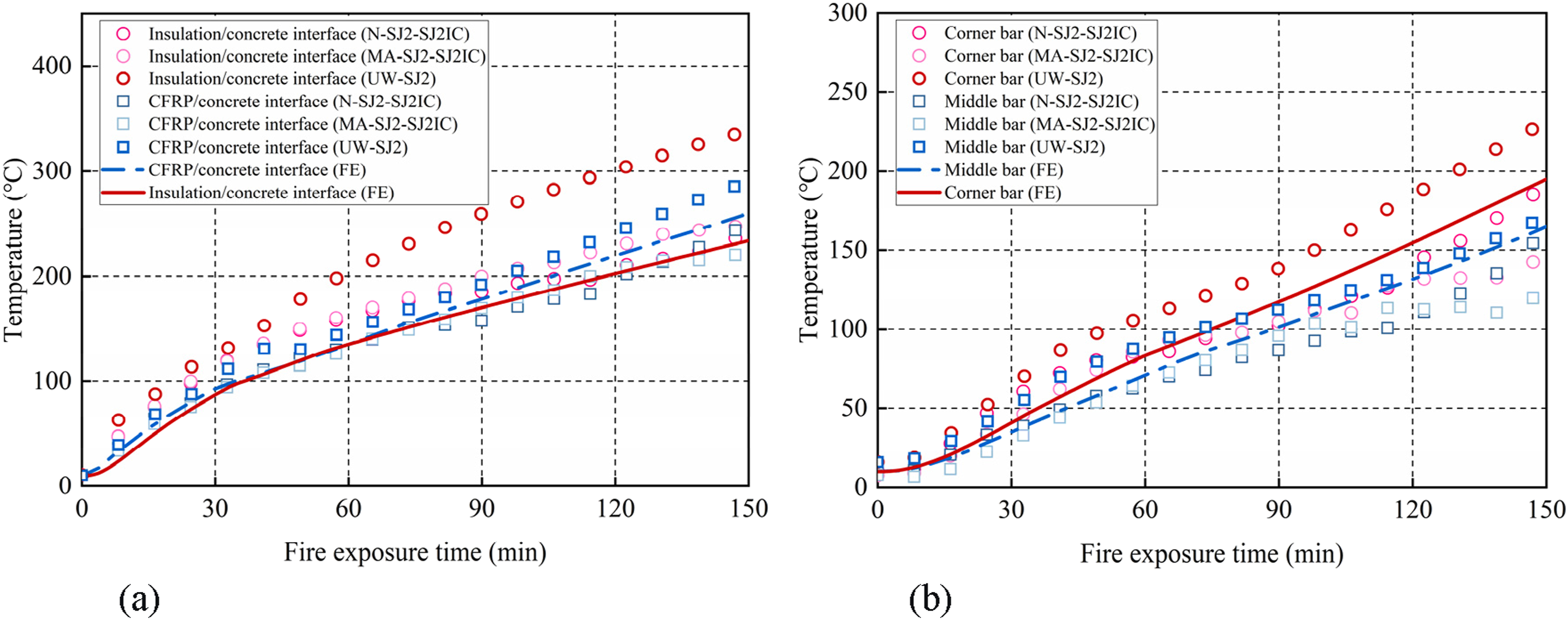
Moment capacity analysis
The moment capacity analysis was performed using the temperature distributions obtained from the validated heat transfer FE model. For any given fire exposure time, the temperatures at various locations of different materials within the beam cross-section was determined directly from the FE results. The flexural capacity analysis accounted for the temperature-dependent degradation of all constituent materials to predict the behavior of insulated CFRP-strengthened beams under fire exposure. The analytical approach followed the 500°C isotherm method recommended in EN 1992-1-2 (2004) and fib Bulletin 38 (2007). This method simplifies the complex temperature distribution by assuming that the concrete retains its mechanical properties at ambient temperatures in regions where the temperatures remain below 500°C, while the concrete exposed to temperatures above 500°C is assumed to have lost its compressive strength. In practical engineering applications, when detailed FE simulations are not feasible, simplified temperature prediction approaches proposed by Gao et al. (2014, 2015b) can be used to estimate the location of the 500°C isotherm within the beam cross-section during fire exposure. In the present study, thermal analysis results indicated that the concrete temperatures in all beam sections remained below 500°C due to the effective protection provided by the insulation systems. Therefore, the reduction in concrete compressive strength was neglected in the subsequent flexural analysis, while the temperature-induced degradation of steel reinforcement and CFRP materials was explicitly considered.
The flexural response analysis was conducted under the following assumptions: (a) The plane-section assumption was adopted, implying a linear strain distribution across the beam depth; (b) The tensile contribution of concrete was neglected; (c) The temperature-dependent yield strengths ( (d) Since the CFRP sheets behaves as a brittle linear-elastic material in tension, a linear constitutive model was adopted for the CFRP sheets.
During fire exposure, the insulated CFRP-strengthened RC beams with different anchorage systems exhibited two predominant flexural failure modes: (i) Concrete crushing of the compression zone prior to CFRP debonding, and (ii) CFRP debonding following the yielding of the tensile steel reinforcement.
Based on the experimental observations, the CFRP contribution was considered during the early stages of fire exposure for the specimens with the UW anchorage system, when the debonding failure had not yet initiated. For the specimens equipped with the MA anchorage system, the CFRP contribution was evaluated by assuming an infinitely bond length, owing to the restraining action provided by the MA system. The flexural capacity of the insulated CFRP-strengthened RC beams was then evaluated using analytical formulations corresponding to these two different failure modes. Assuming that the fire-exposed section reaches its ultimate limit state, the stress and strain distributions in the concrete, the tensile steel reinforcement, and the CFRP sheets are illustrated in Figure 17. (i) Failure governed by concrete crushing Force equilibrium and strain compatibility of the beam cross-section.

When the failure is governed by the crushing of the top concrete layer, the tensile strain in the CFRP sheets increases progressively as the loading continues, and the tensile steel reinforcement first reaches its yield strength. With further loading, the compressive strain in the concrete attains its ultimate limit, 

The tensile stress in the CFRP at a given temperature (ii) Failure governed by CFRP debonding


When the flexural failure is governed by debonding of the CFRP sheets, the tensile steel reinforcement yields, whereas the compressive steel reinforcement remains elastic. The strain in the CFRP sheets reaches its effective limit, expressed as:
The corresponding effective CFRP stress at high temperatures, 

The debonding stress 
The strain compatibility relationships for the concrete and compression steel reinforcement are expressed as:

The corresponding force and moment equilibrium equations are expressed as:

Before evaluating the ultimate moment capacity, two verification steps were conducted. First, it was determined whether the flexural capacity was governed by concrete crushing or CFRP debonding. Second, it was verified whether the strain in the compression steel reinforcement (
Figure 18 illustrates the predicted evolution of the normalized moment capacities of the four tested beams during fire exposure, expressed relative to their corresponding ambient-temperature capacities. As shown in Figure 18(a), the specimens N-SJ2-SJ2IC and MA-SJ2-SJ2IC exhibited similar capacity degradation trends during the initial 60 minutes of exposure due to their identical insulation configurations. However, their behaviors diverged significantly at later stages, primarily because of the presence of the MA anchorages in the specimen MA-SJ2-SJ2IC. The moment capacity contributions from the concrete compression zone and the tensile steel reinforcement exhibited only minor reductions, which reflected the effective thermal protection provided by the insulation layer. In contrast, the overall decline in flexural capacity was predominantly governed by the progressive degradation of the CFRP contribution as the duration of fire exposure increased. As the temperature increased, the bond strength between the CFRP sheets and the concrete substrate deteriorated, leading to a rapid increase in the required effective bond length. Once the actual bond length became shorter than this required length, the EB CFRP system was considered to have failed, resulting in a complete loss of its flexural contribution (Dai et al. 2013). After approximately 60 minutes of exposure, the CFRP strengthening system in the specimen N-SJ2-SJ2IC was fully debonded, and the residual flexural capacity was carried solely by the reinforced concrete section. In contrast, the CFRP system in the specimen MA-SJ2-SJ2IC remained effective at both ends owing to the restraining action of the MA anchorages, and its residual flexural capacity was therefore evaluated by assuming an infinitely extended effective bond length. Predicted normalized moment capacity of insulated CFRP-strengthened beams during fire exposure. (a) N-SJ2-SJ2IC and MA-SJ2-SJ2IC; (b) UW-MortarIC and UW-SJ2.
In Figure 18(b), the normalized moment capacity of the specimen UW-MortarIC exhibited a noticeably slower degradation rate than that of the specimen UW-SJ2 during the initial 50 minutes of fire exposure. This behavior is primarily attributed to the higher moisture content of the mortar insulation layer in UW-MortarIC, which delayed the temperature rise during the early heating stage (as discussed in the preceding section). Furthermore, between approximately 30 and 80 minutes of fire exposure, the overall degradation rate of the Series-II beams (UW-MortarIC and UW-SJ2) remained lower than that of the Series-I beams. This difference can be ascribed to the residual interfacial fracture energy retained by the EB CFRP sheets in the Series-II beams, owing to the restraining effect provided by the UW anchorage system. Specifically, the effective CFRP stress in the Series-II beams reached approximately 90 MPa within the first 60 minutes, compared with 0 MPa and 57 MPa for the specimens N-SJ2-SJ2IC and MA-SJ2-SJ2IC, respectively, over the same period. These results clearly demonstrate that the residual flexural contribution of the CFRP sheets plays a critical role in influencing the fire performance of insulated CFRP-strengthened RC beams. The residual load-carrying capacities of all the specimens after 3 hours of fire exposure exceeded the sustained service load level (i.e., 57.6%) applied during testing, indicating that all beams achieved at least a three-hour fire-resistance rating without failure, which was consistent with the experimental observations. Therefore, the contribution of the residual CFRP strength must be rigorously accounted for in performance-based fire resistance evaluations, particularly when different anchorage systems are employed.
Conclusions
This study presented a comprehensive experimental and numerical investigation on the fire performance of insulated CFRP-strengthened RC beams with different anchorage and insulation systems. The effects of anchorage configuration and insulation scheme on the temperature distribution, deformation behavior, and residual flexural capacity were systematically examined. The key conclusions can be summarized as follows: (a) Under ambient conditions, the two CFRP-strengthened RC specimens (MA-0 and UW-0) failed through intermediate crack (IC)-induced debonding of the externally bonded CFRP sheets, achieving approximately 27–30% higher ultimate moment capacity than the unstrengthened reference specimen (N-0), which failed by concrete crushing. (b) All the insulated specimens sustained fire exposure for over 2.5 hours without premature failure, thereby achieving a 2.5-h fire resistance rating. The temperatures of the tensile steel bars remained below 250°C, which were well below the critical threshold of 593°C and demonstrated the high thermal efficiency of the insulation layers. Given the effective fire protection provided by the investigated insulation layers, an unstrengthened RC beam with similar insulation would also be expected to achieve a 2.5-h fire resistance rating. However, in the later stages of exposure, the temperatures at the CFRP–concrete interfaces exceeded the T
g
value of the adhesive, resulting in complete bond deterioration and loss of CFRP–concrete interaction. (c) The combined use of insulation and anchorage systems effectively reduced midspan deflection growths during fire exposure. The UW anchorage system demonstrated superior performance during the first 60 minutes due to its restraint against CFRP debonding. In contrast, the MA anchorage system exhibited enhanced performance after approximately 60 minutes of exposure by maintaining tensile force in the CFRP sheets through a cable-like load transfer mechanism. This mechanism preserved flexural resistance even after partial CFRP debonding occurred in the midspan region. (d) A coupled thermal-mechanical numerical model was developed by combining transient heat transfer analysis with a fiber-based sectional approach. The FE-based heat transfer analysis accurately predicted the temperature predictions within the beam cross-sections for various insulation schemes. These temperature results were subsequently used in the theoretical analysis to evaluate the temperature-dependent degradation of material properties. Such a theoretical analysis explicitly accounted for the temperature-dependent degradation of concrete, steel reinforcement and CFRP strengthening system. Numerical predictions showed close agreement with the experimental observations, which accurately captured both the cross-sectional temperature distributions and the degradation trends in flexural capacity. The analysis further revealed that the MA anchorage system effectively maintained load transfer at both beam ends due to its restraining action, whereas the CFRP contribution in the beams with UW anchorages was limited to the early stages of fire exposure prior to CFRP debonding. (e) The experimental results and validated numerical framework collectively confirm that the combined application of appropriately designed fire insulation and anchorage systems can significantly enhance the fire endurance of CFRP-strengthened RC beams. These findings provide a reliable foundation for performance-based fire-resistance design and offer practical guidance for the development and implementation of insulation and anchorage strategies in FRP-strengthened concrete structures requiring improved fire performance.
Footnotes
Acknowledgements
The authors gratefully acknowledge the financial support from the National Natural Science Foundation of China (NSFC) (Grant Nos. 51978398 and 52578370) and the Natural Science Foundation of Shanghai (Grant No. 23ZR1429200).

Funding
The authors disclosed receipt of the following financial support for the research, authorship, and/or publication of this article: The financial support from the National Natural Science Foundation of China (NSFC) (Grant Nos. 51978398 and 52578370) and the Natural Science Foundation of Shanghai (Grant No. 23ZR1429200).
Declaration of conflicting interests
The authors declared no potential conflicts of interest with respect to the research, authorship, and/or publication of this article.