
Abstract
Pumps used for irrigation and drainage are usually connected with induction machines (IMs), which are widely employed in industry and daily life. Relatively severe working conditions force pumps to meet the requirement of high-level reliability. Aiming at the general problem of torsional vibration on shafts, a diagnosing method based on radial electromagnetic vibration is studied, which distinguishes torsional vibration from lateral vibration by characteristic frequencies. The lumped-mass model is utilized to analyze the torsional angle of the rotor. The air-gap magnetic field of the IM is analyzed to obtain the characteristic components induced by torsional vibration. High-frequency harmonics, which are ignored in previous studies, are considered in the analysis of electromagnetic forces to eliminate the influence of mechanical vibration on torsional vibration diagnosis. Characteristic frequencies of radial electromagnetic vibration are analyzed under healthy, torsional vibration, and lateral vibration conditions. Finally, the proposed method is validated by finite element analysis and experiments.
Keywords
Introduction
Induction machines are widely used due to their low cost, durability, and simple characteristics (Wong et al., Oct. 2022; Xia et al., 2021). Pumps connected with induction machines are often used for irrigation and drainage. However, the operating environment of submersible pumps can be severe (Nave et al., Sept.–Oct. 1989). The water where they operate for a long time may contain large amounts of sediment, which may be caught in the impeller and cause load oscillation. The sudden change of the loads leads to torsional vibration on the shafts connecting the pumps and the electrical machines (Thorsen & Dalva, March-April 2001). Long-term torsional vibration may exacerbate the metal fatigue of the shafts and eventually result in shaft breakage. Therefore, it is necessary to analyze and diagnose the torsional vibration on the shafts (Liu et al., 2016; Yang et al., Dec. 2016).
Torsional vibration is challenging to detect and easily confused with lateral vibration. Dedicated diagnosing equipment like pulse sensors, strain gauges, and laser vibrometers are sophisticated and increase the cost of the system (Chen et al., 2023; Koene et al., Dec. 2022). Numerous studies aimed to simplify the torsional vibration diagnosing processes by detecting torsional vibration without specialized equipment. Some processed mechanical signals to diagnose torsional vibration. Chen et al. (Chen et al., 2023) separated torsional vibration from lateral vibration and utilized existing lateral vibration sensors to diagnose torsional vibration. Koene et al. (Koene et al., Dec. 2022) proposed a new signal processing method to decompose the torsional and lateral vibration signals from the vibration data collected by a universal measurement unit. These methods could diagnose torsional vibration and distinguish it from lateral vibration without utilizing expensive equipment. However, at least two accelerometers were used in these methods, which could be further simplified.
The torsional vibration affects not only the mechanical aspects of the systems but also the electrical machines’ operating state, making it possible to detect torsional vibration by processing electromagnetic signals (Shin et al., May–June 2021). Blodt et al. (Blodt et al., Nov.–dec. 2006) found that load torque oscillations, which were regarded as torsional vibration, affected fundamental air-gap magnetic fields, causing phase modulation in stator currents. The electromagnetic torque estimation was used to assess the torsional vibration of the induction machines in (Kia et al., Jan. 2010) and (Henao et al., May 2011). Characteristic frequencies caused by torsional vibration appeared in the decomposition of electromagnetic torque. However, (Kia et al., Jan. 2010) and (Henao et al., May 2011) did not investigate how to distinguish between torsional and lateral vibrations.
Most of the studies about electromagnetic vibration are dedicated to weakening electromagnetic vibration because it is the primary source of noise (Bailly et al., 2019; Kim et al., Aug. 2017; Sun et al., 2022). However, electromagnetic vibration can also be used to diagnose the faults in electrical machines, which is utilized in this article. Di et al. (Di et al., 2014) studied the electromagnetic forces of induction machines and extracted the characteristic frequencies induced by lateral vibration, also known as eccentricity. Guan et al. (Bokai et al., 2022) utilized radial electromagnetic vibration to preliminarily diagnose the eccentricity caused by bearing faults. Torsional vibration influences air-gap magnetic fields and causes electromagnetic vibration in specific frequencies, making it possible to diagnose torsional vibration with electromagnetic vibration (Blodt et al., Nov.–dec. 2006; Chen et al., 2015). However, previous studies have only considered the fundamental wave of the air-gap flux density. Low-frequency vibration caused by the fundamental wave is easily confused with mechanical vibration. Therefore, analysis of high-frequency harmonics is necessary to eliminate the influence of mechanical vibration. A single accelerometer is usually needed to collect the radial electromagnetic vibration signals.
It is challenging to impose torsional vibration on electrical machines in experiments. Previous studies proposed various approaches to couple the torsional vibration with the electrical machine. According to (Zafarani et al., April 2021), the natural frequencies of the systems were calculated, and loads oscillating with these frequencies were applied to the electrical machines to model and analyze the torsional vibration of the machine-pump systems. Zhu et al. (Zhu et al., July–Aug. 2012) utilized the cogging torque of the permanent-magnetic brushless machine as the excitation to facilitate the analysis of torsion vibration. Therefore, no additional external excitation was needed. A small mass was fixed on a disk mounted on the shaft in (Blodt et al., Nov.–dec. 2009; Shin et al., May–June 2021), and (Fournier et al., March 2015), which generated a sinusoidal torque oscillation with a frequency equal to the rotation frequency due to the gravity effect. Healthy bearings guaranteed that the centrifugal forces caused by the unbalanced mass did not lead to air gap eccentricity (Blodt et al., Nov.–dec. 2009).
This article aims to diagnose the torsional vibration with high-frequency radial electromagnetic vibration of induction machines. The characteristic frequencies and spatial orders of electromagnetic vibration induced by torsional vibration are analyzed to distinguish torsional vibration from lateral vibration and healthy states. The high-frequency harmonics in the air-gap magnetic fields, which were overlooked in previous studies, are analyzed to eliminate the influence of mechanical vibration. Section 2 analyzes the motion state of the system under torsional vibration. Section 3 explores the induction machines’ air-gap magnetic field and electromagnetic forces under torsional vibration. In Section 4, the effectiveness of the proposed torsional-vibration-diagnosis method is verified by FEA and experiments.
Torsional Vibration Analysis of an Induction Machine Connected with a Pump
The structure of the induction machine and pump is shown in Figure 1. Torsional vibration occurs when the sediment in the water adheres to the impeller, which further causes the rotor position to oscillate. The rotor is involved in the electromechanical energy conversion of the induction machine. Therefore, a lumped-mass model is built in this section to calculate the amplitude and angular frequency of the rotor's torsional angle (Pindoriya et al., April 2022).

Structure of the system.
The lumped-Mass Model and Motion Equations
The mass of the rotation system is concentrated at the rotor, coupling, and impeller, which are assumed to be rigid. The shafts, instead, are regarded as massless springs. Figure 2 presents a schematic view of the lumped-mass model. θi is the angular position of the ith object, and i = 1, 2, 3. Other parameters are listed in Table 1.

The lumped mass model of the rotating part.
Mechanical Parameters of the Induction Machine and Pump.

The angular positions of the rotor, coupling, and impeller change linearly and synchronously in healthy states, which can be expressed as
When torsional vibration occurs, the angular speeds of the three objects are no longer constant. The motion state of the rotation system can be obtained by solving the kinematic equations of the lumped model. The kinematic equations of the system can be expressed as (Pindoriya et al., April 2022)

Motion States of the Rotating Components
By solving the equations, the rotor position under torsional vibration can be expressed as
The sediment adhered to the impeller causes periodical load oscillation due to the gravity effect. The load oscillation's angular frequency equals the rotating system's angular speed (Blodt et al., Nov.-dec. 2006). For a non-high-speed induction machine with a reasonable mechanical design, the natural frequency is usually much higher than the rotation frequency. Therefore, according to rotor dynamic theories, the natural torsional vibration term in (4) is negligible. The rotor's torsional angle can be further expressed as
Analysis of Magnetic Field Under Torsional Vibration
The rotor position, which is supposed to vary linearly along the circumference in healthy states, oscillates when torsional vibration occurs. Torsional vibration impacts the rotor MMFs because the rotor's magnetic fields depend on the rotor's position. To facilitate the following analysis of MMFs, a function is defined as
Air-Gap MMFs Under Torsional Vibration
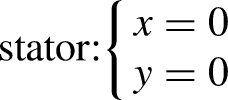
When torsional vibration occurs, stator MMFs are not affected directly, which remains to be (Di et al., 2014)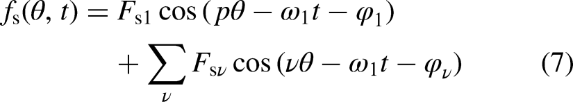

Torsional vibration causes the rotor's angular position and speed to oscillate. Considering (5), the rotor angular position and speed relative to the stator are expressed as

The rotor MMFs under healthy conditions can be expressed as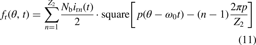
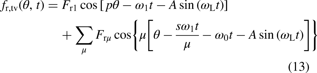
Equation (10) shows the rotor's motion state under torsional vibration. Substituting (10) into (11), the rotor MMFs under torsional vibration can be expressed as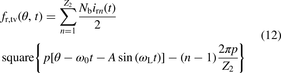
Air-Gap Magnetic Permeance Under Torsional Vibration
The air-gap magnetic reluctance between the stator and rotor can be divided into three parts: the stator-slot reluctance, the rotor-slot reluctance, and the air-gap reluctance. Reluctance introduced by stator slot can be expressed as
The rotor-slot reluctance under healthy states can be expressed as
Considering (10), the rotor-slot reluctance under torsional vibration can be expressed as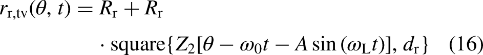
Air-Gap Flux Densities Under Torsional Vibration
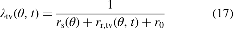
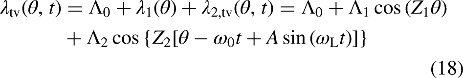
According to the conventional theory, the air-gap flux densities are the product of the air-gap MMFs and air-gap magnetic permeance, which can be expressed as (Sun et al., 2022)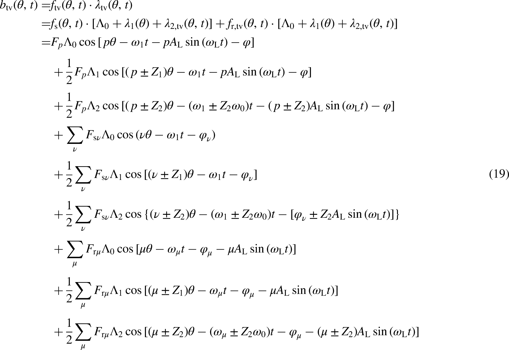
When the stator and rotor cores are saturated, the saturated harmonics are introduced in (19). The saturated harmonics are expressed as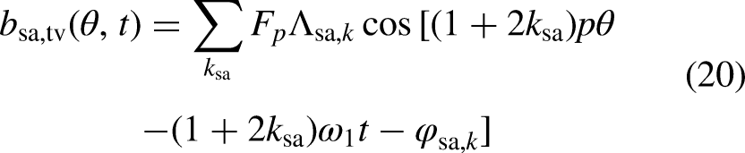
The spatial orders and angular frequencies of air-gap flux densities under torsional vibration are extracted and listed in Table 2. The phase modulation induced by torsional vibration exists in the air-gap flux densities. The characteristic frequencies appear at (f1 ± nfL) and (kZ2f0 + f1 ± nfL), where f1 is the supply frequency, n takes the positive integer, fL equals the rotor's rotation frequency, and (kZ2f0 + f1) is the frequency of rotor tooth harmonics. For n greater than 1, the amplitudes of characteristic components are small enough to be ignored.
Characteristic Air-Gap Flux Density Components Under Torsional Vibration.

Radial Electromagnetic Forces Under Torsional Vibration
The radial electromagnetic forces per unit area can be expressed as (Sun et al., 2022)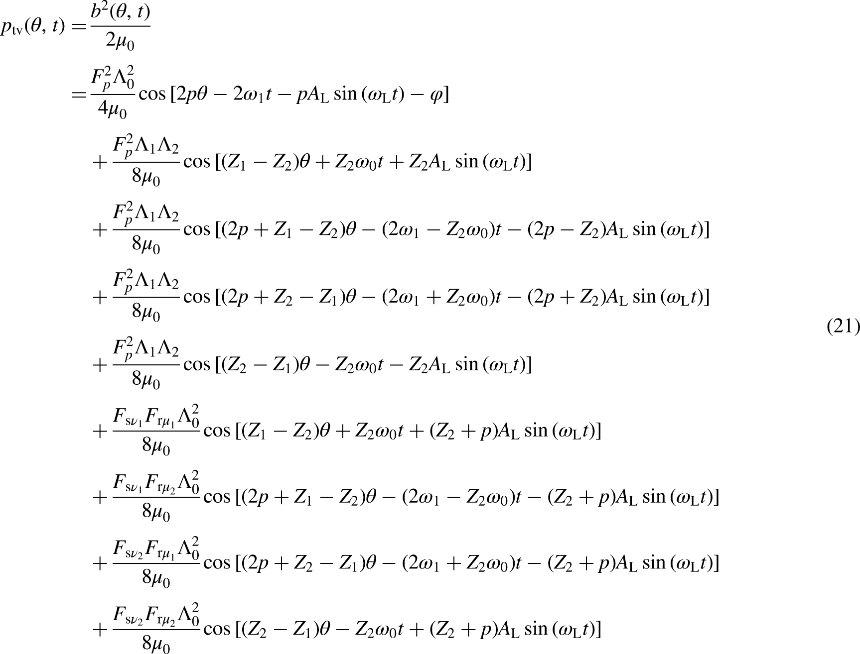
Radial electromagnetic Forces Under Torsional Vibration.

According to (Di et al., 2014), the radial electromagnetic forces under lateral vibration are listed in Table 4. f0 is the rotor's rotation frequency. Considering that fL and f0 are equal, it can be seen that:
Radial Electromagnetic Forces Under Lateral Vibration.

The low-spatial-order components among B1∼D2 cause more significant stator vibration than high-spatial-order components. Therefore, the harmonics with the smallest absolute value of spatial orders can be utilized to diagnose torsional vibration.
The complete diagnosis process is presented in Figure 3. Torsional vibration and lateral vibration introduce components with characteristic frequencies in radial electromagnetic forces. These components appear as the sidebands of the fundamental wave and tooth harmonic waves. Sidebands introduced by torsional vibration have the same spatial orders, causing the same amplitude of electromagnetic vibration. Sidebands introduced by lateral vibration have the different spatial orders, causing different amplitudes of electromagnetic vibration. No sideband appears in healthy state. Therefore, sidebands distinguish the torsional vibration state from lateral vibration state and healthy state according to the amplitude of characteristic components. The effects of mechanical vibration are also eliminated because the frequencies of tooth harmonics are higher than those of mechanical vibration.

The flowchart of the torsional vibrations diagnosis method.
Verification
FEA and experiments are conducted on a 5.5-kW induction machine to verify the proposed method's validity. The main electrical parameters are listed in Table 5. To slow down the angular velocity and reduce the centrifugal force, the induction machine is supplied by a three-phase voltage source at 12.5 Hz in both FEA and experiments.
Electrical Parameters of the 5.5 kW induction Machine.

Verification by FEA
The FEA is carried out according to the four cases listed in Table 6. Case 1 represents the induction machine in a healthy state. Case 2 represents the induction machine in a torsional vibration state, and the oscillating load torque is expressed as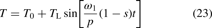
Arrangements of FEA.

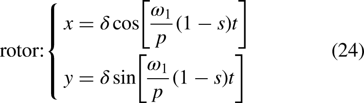
The FEA models are presented in Figure 4. The radial length of the air gap is uneven along the air-gap circumference. The stator and rotor are slightly saturated. The material of the stator and rotor is DW540 Steel, and the B-H curve is shown in Figure 5. The 2D transient-magnetic FEA is performed on the induction machine to obtain air-gap flux densities in both temporal and spatial domains. The governing equation is described as (Di & Bao, April 2024; Pyrhonen et al., 2008)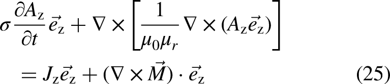


The meshed FEA model and the distribution of magnetic flux densities. (a) The center-aligned model. (b) Part of the center-unaligned model.

The B-H cruve of DW540 steel.
The 2D FFT of the flux densities is performed, and the results in different spatial orders are presented in Figure 6 (a) to (d):
In Figure 6 (a), the 12.5-Hz component is the fundamental wave. The 0-Hz and 25-Hz components are caused by torsional vibration and lateral vibration. In Figure 6 (b), the 37.5-Hz component is the saturation harmonic. The 25-Hz and 50-Hz components are caused by torsional vibration and lateral vibration. In Figure 6 (c) and (d), the 310-Hz and 335-Hz components are the rotor tooth harmonics. The 297.5-Hz, 322.5-Hz, 347.5-Hz components are caused by torsional vibration and lateral vibration.

The 2D FFT spectrum of air-gap flux densities at various spatial orders. (a) p = 1. (b) p = 3. (c) p = 25. (d) p = 27.
The 1st-, 25th-, and 27th-order air-gap flux densities are corresponding to A0, B0, E0, and F0 in Table 2. The sidebands of the dominant wave are caused by torsional and lateral vibration. Comparing the marked components in Figure 6 and Table 2, the frequencies and spatial orders are well-matched. Minor errors are caused by insufficient resolution.
The radial electromagnetic pressures under healthy, torsional vibration, and lateral vibration states are calculated by (21). The results are presented in Figure 7 (a) to (d):
In Figure 7 (a), the 25-Hz component is the pressure caused by the fundamental wave. The 12.5-Hz and 37.5-Hz components are induced by torsional vibration. In Figure 7 (b) and (d), the 360-Hz and 335-Hz components are induced by lateral vibration. In Figure 7 (c) and (d), the 347.5-Hz component is the pressure induced by tooth harmonics. The 335-Hz and 360-Hz components are induced by torsional vibration.

The spectrums of radial electromagnetic forces. (a) p = 2. (b) p = –1. (c) p = –2. (d) p = –3.
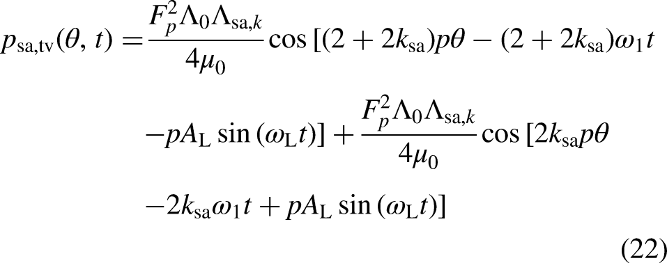
Components with their spatial order absolute values greater than two are ignored. According to (22), the saturation harmonics have the same frequencies and spatial orders with the fundamental wave. The marked frequencies in Figure 7 match the results in Table 3 and Table 4. Figure 7 (b), (c), and (d) indicate that radial electromagnetic pressures caused by torsional and lateral vibration have the same frequencies but different spatial orders.
Verification by Experiments
To simulate the faulty states, some mechanical components of the machine and pump are modified as follows:
1) To simulate the torsional vibration state, a small amount of lead is added to one side of the impeller and sealed with a thin iron sheet, which is shown in Figure 8 (a). The mass of the lead is 0.25 kg, which generates load oscillation with an amplitude of 0.25 Nm, considering that the radius of the impeller is 0.1 m. The angular frequency of load oscillation equals the system's angular speed (Blodt et al., Nov.–dec. 2006). 2) To simulate the lateral vibration state, the coupling is mounted with minor center unalignment, which is shown in Figure 8 (b). The angular frequency of lateral vibration equals the system's angular speed (Blodt et al., Nov.–dec. 2009).

Modified mechanical components. (a) Healthy and faulty impellers. (b) Center-aligned and center-unaligned couplings.
Corresponding to the FEA, the experiments are conducted according to the four cases listed in Table 7. The power supply, induction machine, pump, and other experimental equipment are presented in Figure 9. An inverter supplies the induction machine at 12.5 Hz. An accelerometer is used to collect the vibration signal. The model of the accelerometer sensor is PCB 053B03.

The power supply, 5.5-kW induction machine, pump, and measuring devices.
Arrangements of Experiments.

The radial electromagnetic forces act on the stator teeth and result in vibration. In this experiment, the accelerometer is mounted on the top of the machine shell to collect the vibration signals in the radial direction. The vibration signals under four cases are presented in Figure 10 (a), (b), (c), and (d), respectively. And their power spectral densities are presented in Figure 11 (a), (b), (c), and (d), respectively.

Tested radial electromagnetic vibration. (a) Case1. (b) Case 2. (c) Case 3. (d) Case 4.
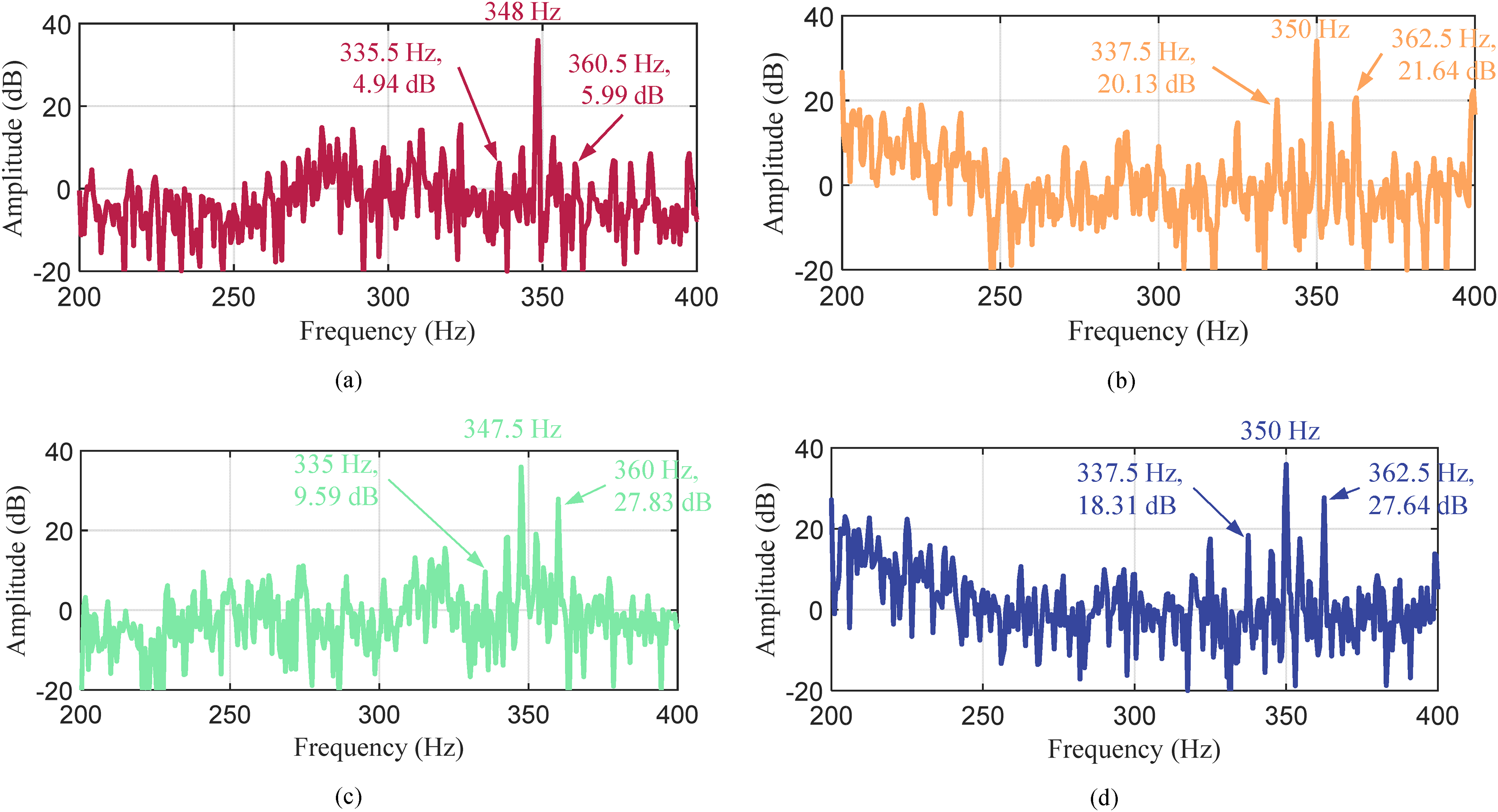
Spectrums of tested vibration signals. (a) Case1. (b) Case 2. (c) Case 3. (d) Case 4.
When torsional vibration occurs, both sidebands around the dominant wave have increased amplitudes, which is well-matched with the analytical and FEA results. When lateral vibration occurs, only one sideband's amplitude increases. Therefore, the frequency of 335.5 Hz in Figure 11 (b) can be used to diagnose the torsional vibration of the studied rotating system. The corresponding dominant wave has the smallest absolute value of spatial orders, and its frequency is 350 Hz, which matches the analysis in Section 3.
Conclusion
This paper introduced a torsional vibration diagnosis method for induction machines based on electromagnetic vibration. The rotor position was calculated by the lumped-mass model. The air-gap magnetic flux densities and electromagnetic forces under torsional were analyzed using analytical methods. High-frequency harmonics were considered to eliminate the influence of mechanical vibration, which was ignored in previous research. The electromagnetic force components induced by torsional vibration had characteristic frequencies and spatial orders, which distinguished torsional vibration from lateral vibration.
To validate the method, a 5.5-kW induction machine connected with a pump was modelled in FEA and used as the experimental object. The vibration signals under healthy, torsional vibration, and lateral vibration conditions were collected in the experiments and compared with the analytical and FEA results. Torsional vibration causes two sidebands, and lateral vibration only causes one sideband, which was utilized to distinguish torsional vibration from lateral vibration. The benefits of the method are as follows.
3) Electromagnetic vibration was utilized to diagnose torsional vibration, which could effectively distinguish torsional vibration from lateral vibration. 4) High-frequency harmonics in rotor MMFs and high-order tooth harmonics in rotor permeance were considered. The high-frequency electromagnetic vibration was separated from the mechanical vibration, which made the diagnosis more accurate. 5) Only one accelerometer was used to diagnose the torsional vibration, which reduced the cost of diagnosis.
Footnotes
Acknowledgements
This work was partly supported by the National Natural Science Funds of China under Grant 51977055, and the Major Science and Technology program of Anhui Province under Grant 201903a05020042. Besides, the authors would like to acknowledge the support of Anhui Province's key laboratory of Large-scale Submersible Electric Pump and Accoutrements for providing the experimental platform.
Funding
The authors received no financial support for the research, authorship, and/or publication of this article.
Declaration of Conflicting Interests
The authors declared no potential conflicts of interest with respect to the research, authorship, and/or publication of this article.