
Abstract
Introduction
In the process of aerospace structure design, finite element method is commonly used to assist structure design and analysis. Therefore, the high reliability of finite element model (FEM) is required in engineering. It is often necessary to update the preliminary FEM according to the test results to obtain the high-precision one.1,2 Updating the FEM is to adjust the uncertain parameters in the model so that the numerical model can reflect the dynamic characteristics of the actual product. 3 There are two main types of current model updating techniques, the one is updating method for system matrix elements and the other is updating method for structural parameters.2,4 And parametric updating method is widely used because of its clear physical significance. Structural material parameters are often updated for individual components, and the link relationships are updated based on the accuracy of the component model for the assembly. 1 It is difficult to accurately describe the dynamic characteristics of the assembly in finite element modeling because of the complex link relationships in the assembly structure. 5 The existing finite element software has integrated the corresponding interaction units for welding, screw and other link relations. 6 In addition, some scholars have established thin layer elements at the position of the joint.6–8 The parameters of thin layer elements were updated by the experimental results to make the dynamic characteristics of the model consistent with the actual structure.
In engineering practice, the finite element modeling object usually has many components, and the modeling process is more complicated. In order to simplify this process, tie constraint is often used to simulate the link relationship. Tie constraint is used to make one surface adhere to another. The degree of freedom (DOF) of the nodes selected from the slave surface is consistent with the DOF of the closest node on the master surface. The constrained area of the structure will affect the dynamic characteristics of the structure, so the constrained area of the connection position should be determined to improve the accuracy of the model. To solve the problem of model updating of constrained area, it is difficult to realize the model updating method of united simulation with optimization algorithm and commercial finite element software. 9 Because the model needs to adjust the constraint nodes during the updating process, the automatic operation of this process is still a difficult problem. The introduction of surrogate model can effectively combine with the optimization algorithm to improve the updating efficiency. 10 And the introduction of inverse surrogate model (ISM) can further improve the efficiency of the model updating. 11 The ISM is used to characterize the relationship between the structural response and the parameters to be updated, and the parameters can be directly obtained by inputting the response obtained by the experiment into the ISM. It can avoid the iterative calculation process of the optimization algorithm. Artificial neural network (ANN) has excellent ability to describe nonlinear relations, 2 so we use ANN to establish the ISM between the structural modal response and the constrained area, so as to complete the model updating. Finally, the method is verified by experimental research.
The rest of this article is organized as follows. The Section 2 introduces the object to be updated, and introduces the definition of constrained area and its relationship with natural frequency. The Section 3 introduces the process framework of the model updating method. In Section 4, a numerical example is given to verify the effectiveness of the proposed method. Finally, we came to some conclusions in Section 5.
Object to be updated
Definition of constrained area
The constrained area is the object to be updated in our study. Before studying the relationship between the constrained area and the natural frequency, we define the constrained area as follows: taking the shape of the maximum stress region in the contact region as the characteristic shape, the area formed by scaling the characteristic region. The link relationship is established by constraining all nodes in the preceding area. The definition of constrained area for the bolt joint is that the area surrounded by a circle centered on the center of the bolt hole. The constrained area is determined by the radius.
Since the interaction is established by tying nodes, it is possible that the number of nodes in the circular area will not change when the radius changes. Therefore, we define the constrained area under this constraint condition when the number of nodes just changes as the radius increases. Since the area within a certain distance between the master surface and the slave surface in the contact area can be effectively constrained, the constrained area of the master surface and the slave surface is not required to be equal in the modeling process. And the effective constrained area only needs to meet the above definition. In the actual modeling, the constrained area of a certain surface can be set to be slightly larger, and the constrained area of the other surface only needs to be adjusted during the model updating process.
Relationship between constrained area and natural frequency
The relationship between constrained area and natural frequency is studied by a simple finite element example. ABAQUS commercial finite element software was used to build two plates with specifications of 500 mm × 100 mm × 5 mm. The diagram of two plates is shown in the Figure 1. The plate material is aluminum alloy, its density is set to 2700 kg/m3, and the elastic modulus is set to 71 GPa. The length of the contact area between the two plates is 100 mm and the two plates are constrained by “TIE”, which can tie two separate surfaces together so that there is no relative motion between them. One end of the structure is fixed to form a cantilever plate structure. We select the center of the bolt hole as the center of the circle, change the radius to select the constraint area, and calculate the natural frequency of the structure.
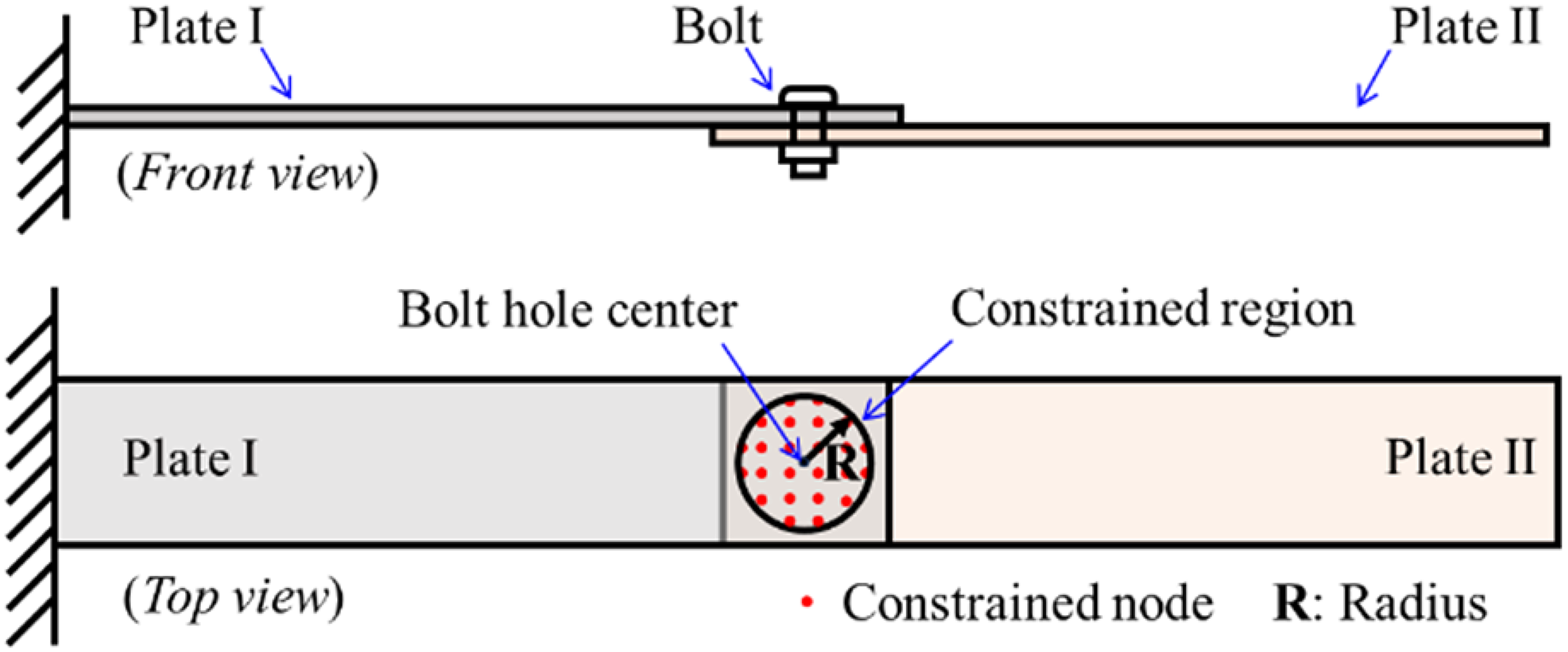
Diagram of two plates with “TIE” constraint.
After meshing the structure, we can change the constrained area by modifying the radius of the constrained region. Here, six radius conditions are selected to study the relationship between constrained area and natural frequency. The modal shapes are used to distinguish the natural frequency orders, and the results are drawn as shown in Figure 2. It can be seen from the figure that with the increase of the number of constrained nodes, that is, the increase of the constraint area, the natural frequency of the structure increases. Therefore, the FEM can be made consistent with the actual structure dynamics by updating the constrained area of the model. The factors that affect the natural frequency, such as the stiffness of joint material and the preload on bolt joint, can be represented by different constrained areas.
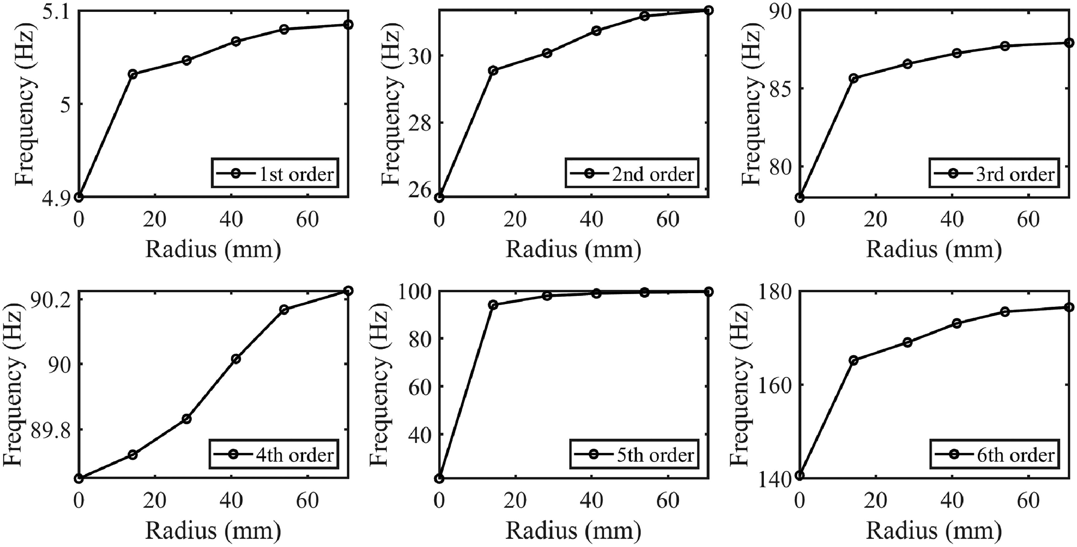
The relation between the natural frequencies and radius of constrained region.
Model updating method
According to the optimization design framework combined experimental data and machine learning in literature, 12 we proposed a model updating framework as shown in Figure 3. Taking bolted link as an example, the constrained area of the connection position is taken as the updated object. Different radii are selected for experimental design, and the constrained area is formed as the input set of the interaction relation of the FEM. The designed samples are substituted into the FEM for modal analysis to obtain the natural frequency. The design samples of the object to be updated is combined with the corresponding modal analysis results to form a dataset. ANN is used to establish the relationship between natural frequency and constrained area. The frequencies are the inputs of the net and the constrained areas are the output of the net. Finally, the test natural frequency input into the trained ANN to get the constrained area. The FEM is updated according to the ANN calculation results.
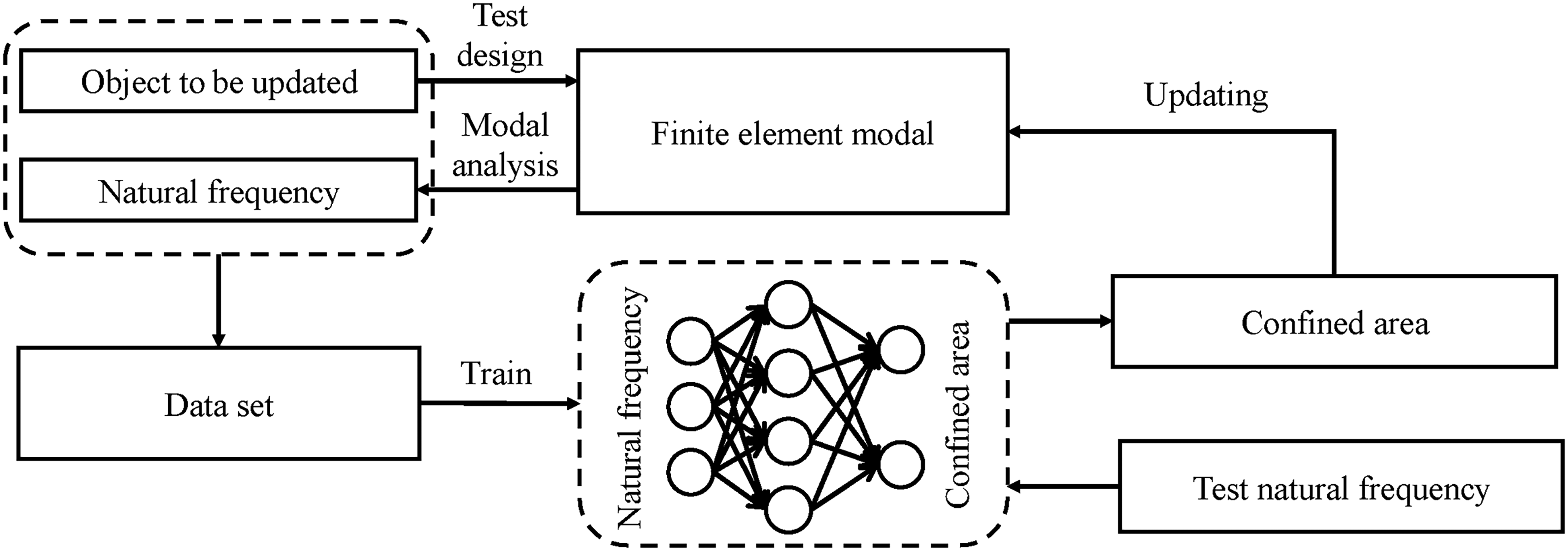
Model updating framework.
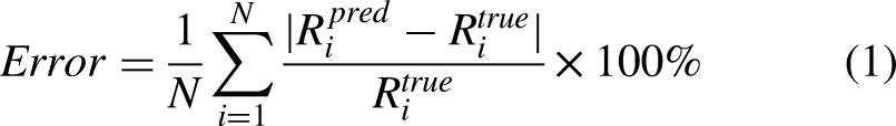
The neural network structure contains a hidden layer. The number of neurons in input layer is determined by the number of natural frequencies that used for model updating. The number of neurons in output layer is determined by the number of bolts. The number of hidden layer neurons was optimized by genetic algorithm. The mean square error (MSE) of test set is used to evaluate the optimization result, which can be calculated by formula
Finite element model updating (FEMU) of plate with bolts
In order to verify the proposed FEMU method, two cases are taken as the research objects, which are the single bolt constrained plates and double bolts constrained plates respectively. The structures are shown in the Figure 4. The dimensions of both plates are 500 mm × 100 mm × 2 mm. Before using the FEM to construct the database, the mesh independence test of the FEM is carried out. After eliminating the influence of mesh, the material parameters of the FEM are updated to exclude other factors that may affect the finite element analysis results. Material parameters mainly include density and elastic modulus. The density is calculated by measuring the structure mass and volume. For the elastic model, the natural frequency of the single plate structure is obtained by modal test, and the elastic modulus of the material is updated by comparing with the finite element analysis frequency.
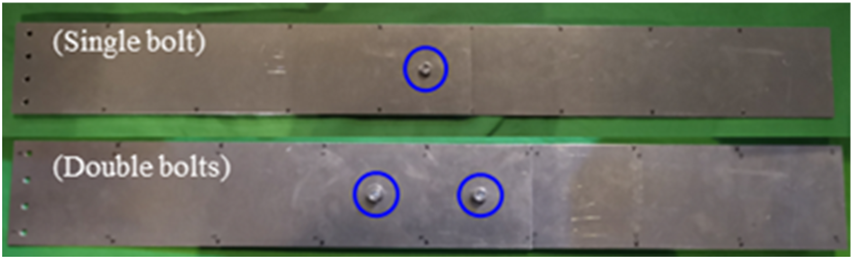
Plate structure for two cases.
After obtaining the exact material parameters, the FEMs of the two plates linked by bolts is established. In these models, the only factor affecting the accuracy is the difference between the FEM and the actual physical structure at the link position. Therefore, the proposed model updating method is adopted to update the FEM with the joint modeling constraint area as the updated object. The data sets of two cases can be constructed by the established FEMs, and the data sets include the first six non-zero natural frequencies of the free state and constrained areas of each bolt. Divide the above data into a training set and a test set. Using training set for network training, and test set for trained net testing. The result was evaluated using mean relative error of radius of constrained area for each case, which can be calculated by formula (1). The mean relative error between the network predicted values and label values on the test sets are 0.84% for case with single bolt and 5.2%, 3.0% for case with double bolts. It shows that the neural network model can accurately describe the relationship between the natural frequency and the constrained area.
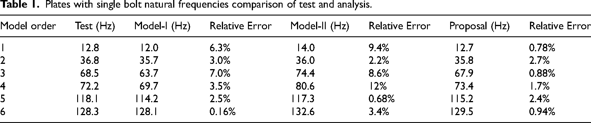
The free state modal test is carried out for two cases by hammer impact testing. The structures are suspended by elastic rope to simulate the free state. The impact hammer model is PCB 086C02. The sensor adopts the PCB 356M41/015CA three-directional acceleration sensor. Data collection using the LMS SCADS-X III data collection device. A ThinkPad laptop with TestLab modal analysis software was used for data recording and analysis. The first six natural frequencies of two cases are shown in Tables 1 and 2 respectively. The test natural frequency is used as the neural network model input. The constraint area of the bolt link position in the FEM is obtained by using the neural network model. According to the results of neural network calculation, the first six natural frequencies of two cases are analyzed. The comparison of test results and finite element analysis results are shown in Tables 1 and 2. In order to reflect the improvement of model precision, the common simplified modeling methods are used to model the structure of two cases, which include two methods, the one is to constrain the edge nodes of the bolts hole (Model-I) and the other is to constrain all nodes of the contact surface (Model-II). The natural frequencies calculated by this model are shown in Tables 1 and 2. It can be seen from the tables that the models established by the conventional methods have lower precision, indicating that the conventional models need to be updated. It can also be seen from the table that the updated FEM using the proposed method has higher precision. At the same time, it is shown that the link relation of the actual physical structure can be better described by using the constrained area as the updated object.
Plates with single bolt natural frequencies comparison of test and analysis.
Plates with double bolts natural frequencies comparison of test and analysis.

Conclusion
In this paper, a model updating method for the link relation is proposed, which takes the constrained area of the structure connection as the updated object. It can improve the calculation accuracy of the FEM. The relationship between natural frequency and constrained area is established by ANN. This neural network model acts as an inverse surrogate model of the FEM, which avoids the iterative in the model updating process, simplifies the model updating process, and improves the efficiency of engineering structure modeling.
Footnotes
Acknowledgements
The authors wish to acknowledge the research project of State Key Laboratory of Mechanical System and Vibration MSV202408 and the experimental platform of Xi'an Aerospace Propulsion Institute.
Funding
The author(s) received no financial support for the research, authorship, and/or publication of this article.
Declaration of conflicting interests
The author(s) declared no potential conflicts of interest with respect to the research, authorship, and/or publication of this article.