
Abstract
Addressing prevalent issues such as substantial size and inadequate precision in the air gap adjustment mechanisms of adjustable-speed magnetic couplers, this study introduces an innovative controllable electromagnetic hybrid magnetic coupler. This coupler utilizes electromagnetic gap adjustment for precise, non-contact speed regulation. A comprehensive electro-magnetic-thermal-stress coupling model is established, grounded on the principles of electromagnetic induction and heat transfer under variable air gaps. Numerical simulations are conducted, assessing temperature and stress variations under different scenarios involving permanent magnet width, air gap length, winding slot depth, and coil turn count. The optimal parameters of the core device-electromagnetic gap adjuster are obtained by orthogonal experimental method, and the results show that when the width of the permanent magnet is 5 mm, the length of the air gap is 1.5 mm, the depth of the winding slot is 10 mm, and the number of turns of the coil is 14, the mechanism has the lowest steady-state field temperature rise of 23.689 °C. This research lays a foundational basis for advanced mastery of controllable electromagnetic hybrid variable air-gap transmission technology.
Keywords
Introduction
The speed-adjustable magnetic coupler represents a novel form of speed-regulating apparatus, distinguished by features such as light load initiation, overload safeguarding, vibration isolation, among others.1,2 This technology has garnered significant interest from scholars globally. Recently, the gap adjustment mechanism of the adjustable-speed magnetic coupler is characterized by its large size, predominantly utilizing a linkage mechanism. This design presents challenges such as low precision in adjustment, slow operational speed, inconvenient installation, and limited adaptability to the confined and challenging conditions typically found in underground coal mines.
Speed-adjustable magnetic couplers can be broadly categorized into three groups: radial cartridge magnetic couplers, axial disk magnetic couplers, and cage-type asynchronous magnetic couplers. Kang et al. conducted a study on torque calculation and parameter analysis of radial synchronous type magnetic couplers, along with experimental validation. 3 Lubin et al. explored the analytical expressions for the force and torque of axial disk magnetic couplers, as well as the transfer performance under various conditions. 4 Ge et al. proposed an asynchronous magnetic coupler utilizing a squirrel-cage rotor from a three-phase asynchronous motor. This design offers a broader linear operating range, increased overload capacity, and effectively reduces the load effect on the motor. 5 The cartridge magnetic coupler is characterized by its lightweight feature. However, achieving a complete balance of axial force is challenging. 6 This imbalance can significantly effect the bearing life. On the other hand, the double-disk structure of the disk magnetic coupler can counteract the axial force but requires a larger space. 7 In an effort to address the limitations of both designs, Wang et al. introduced a composite magnetic coupler based on flexible transmission technology. They developed an equation for calculating the magnetic field of the air gap and established an electromagnetic torque model of the space magnetic field. Their research concluded that this device exhibited a stronger overload protection capability, as demonstrated through prototype experiments. 8 While the magnetic coupler enables contactless transmission, the eddy current loss produced by the copper disk during operation can result in equipment temperature elevation. Excessive temperature rise may cause permanent magnet demagnetization and failure.9,10 Additionally, the thermal stress variation due to temperature fluctuations can lead to component deformation and damage. 11 Consequently, the multi-physical field coupling analysis of the magnetic coupler, encompassing electricity, magnetism, heat, and stress, has emerged as a significant challenge. 12 Cheng et al. developed a semi-analytical model for estimating the temperature and used the magnetic equivalent circuit and Kirchhoff's law to efficiently and quickly calculate the eddy current losses as a heat source. 13 Marignetti et al. performed a finite element analysis using a dynamic coupling approach between temperature and fluid. This analysis offered theoretical insights into the temperature rise characteristics of disk-type magnetic couplers. 14 Guo et al. utilized the magnetic circuit method to theoretically calculate the eddy current loss of the conductor rotor in the high-power adjustable-speed disk magnetic coupler. They conducted simulation and experimental studies to determine the temperature and remanent magnetization of the permanent magnet under various rotational differences and air gaps. 15 Fan et al. analyzed the electric-magnetic-thermal coupling mechanism of multiple physical fields inside a new compound electromagnetic linear actuator, established an accurate numerical model of the two-way coupling of electric-magnetic-thermal multi-physical fields, and quantitatively investigated the distribution of energy consumption as well as the transient characteristics of the temperature distribution with respect to time and space of the device in different driving modes and under different operating conditions. 16 In summary, researchers both domestically and internationally have conducted numerous studies on the speed-adjustable magnetic coupler. However, none of these studies have effectively addressed the issues related to the large size of the gap-adjusting mechanism and the poor adjustment accuracy. Furthermore, the research on multi-field coupling, such as the interactions between electricity, magnetism, heat, and stress, remains insufficiently explored. Consequently, there is a pressing requirement for a novel magnetic coupler design capable of achieving precise gap adjustments between the conductor rotor and the permanent magnet rotor. This innovation would enhance the energy-saving efficacy of speed regulation under variable torque load and constant torque load conditions.
A new type of controllable electromagnetic hybrid magnetic coupler is proposed. The air gap between copper disk and permanent magnet can be accurately adjusted by the built-in electromagnetic gap adjuster. The structure of the controllable electromagnetic hybrid magnetic coupler is designed. Based on electromagnetic induction theory and heat transfer theory under variable air gap, an electric-magnetic-thermal-stress coupling model was established, and a multi-physics coupling simulation platform was built to simulate the temperature rise distribution characteristics of the device under the influence of different permanent magnet widths, air gap lengths, winding slot depths and coil turns. The variation laws of temperature and stress during electromagnetic gap adjustment were analyzed. Finally, the optimal parameters of the electromagnetic gap adjuster are obtained by orthogonal experiments.
Structure of controllable electromagnetic hybrid magnetic coupler
The controllable electromagnetic hybrid magnetic coupler comprises an input shaft, a copper conductor disk, a yoke iron disk, a permanent magnet, a slotted aluminum disk, and an electromagnetic gap adjuster and so on. The structure is illustrated in Figure 1. The controllable electromagnetic hybrid magnetic coupler is mainly divided into two main parts: the power transmission mechanism and the electromagnetic gap adjustment mechanism.
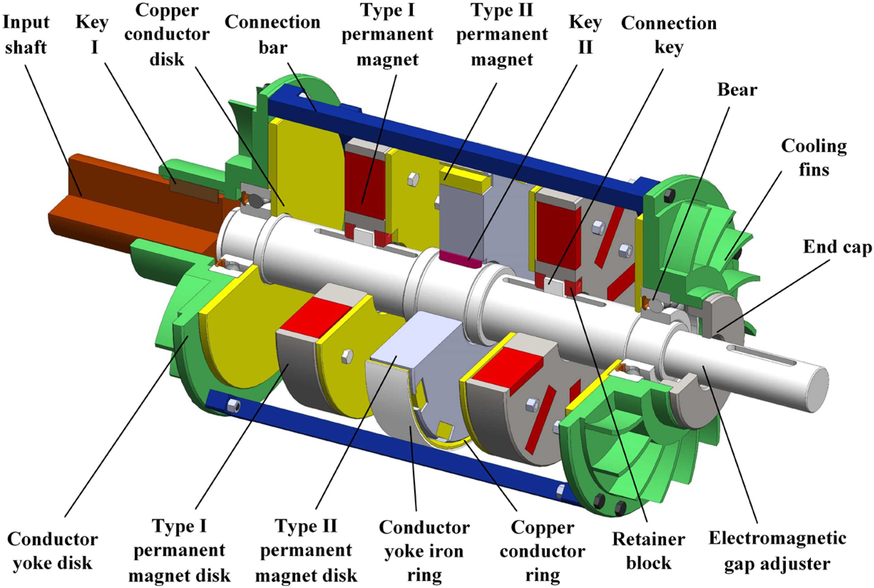
Structure of controllable electromagnetic hybrid magnetic coupler.
Combining the characteristics of the current axial disk magnetic coupler and radial cylinder magnetic coupler, a new type of controllable electromagnetic hybrid magnetic coupler power transmission mechanism has been designed. The permanent magnets are magnetized from the axial and radial directions at the same time, and the copper conductor cuts the magnetic lines of force at the same time to increase the electromagnetic damping, so that under the condition of the same dimensions, the structure can increase the area of induced magnetic field and greatly improve the transmission efficiency. The power transmission mechanism works as follows:
From an axial perspective: the input shaft rotates, and the key I connection drives the conductor yoke iron disk and copper conductor disk of the controllable electromagnetic hybrid magnetic coupler to rotate, and due to the principle of electromagnetic induction, relative motion is generated within the axial air gap between the copper conductor disk and the type I permanent magnet disk and there is a rotational difference between the two rotational speeds, which generates a change in magnetic flux through the copper conductor disk every moment and a change in the magnetic field in the copper conductor disk through the cutting of the magnetic lines of force. The magnetic flux changes every moment through the copper conductor disk by cutting the magnetic lines of force to produce eddy currents, the induced magnetic field produced by the eddy currents interacts with the magnetic field produced by the type I permanent magnet, and the magnetic force produced by the rotational difference drives the type I permanent magnet disk to rotate in the same direction as the copper conductor disk, driving the output shaft to rotate. From the radial point of view: due to the rotation of the connecting rod, it can drive the copper conductor ring installed in its inner side to rotate, similarly, in the radial air gap between the copper conductor ring and the type II permanent magnet disk to produce relative motion, the changing magnetic field in the copper conductor ring by cutting the magnetic lines of force to produce eddy current, the induced magnetic field generated by the eddy current and the type II permanent magnet generated by the interaction of the magnetic field, due to the difference in the magnetic force generated by the drive type II permanent magnet disk. As the copper conductor ring rotates in the same direction, it transmits power and drives the load to do work.
The axial movement gap adjustment function is mainly realized by the electromagnetic gap adjuster, the structure of which is shown in Figure 2. The winding, silicon steel sheet, slotted ring and connecting key and other parts together form the axial moving parts, and the area between the winding and the permanent magnet is the air gap for the exchange between the physical fields. In operation, the winding is energized with a time-varying three-phase alternating current, which generates a parallel moving air gap magnetic field, which produces an electromagnetic attraction under the interaction with the excitation of the permanent magnets and pulls the moving part (axial moving part) of the electromagnetic gap adjuster to move linearly within the gapping range as shown in Figure 2. Only by changing the phase sequence of any two phases of the winding or the magnitude of the external current, the moving direction and speed of the axial moving part can be changed, in which the connecting key in the axial moving part is assembled with the type I permanent magnet disk in the power transmission mechanism, so as to transfer the power, adjust the air gap between the type I permanent magnet disk and the copper conductor disk in the power transmission mechanism, and realize the function of speed regulation.
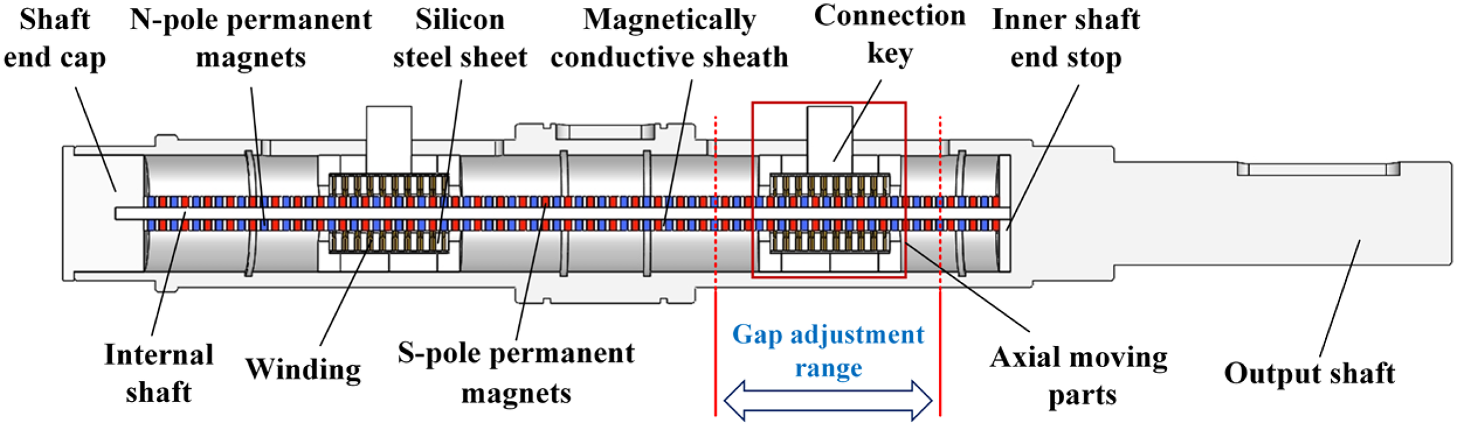
Structure of electromagnetic gap adjuster.
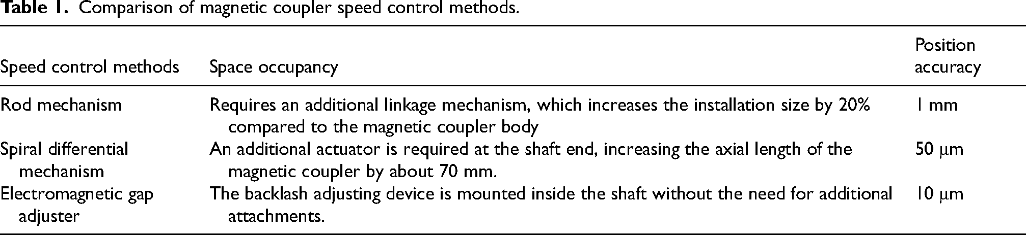
Adjustable-speed magnetic couplers have attracted much attention because of their good speed regulation performance, while the current speed regulation mechanism of most adjustable-speed magnetic couplers still suffers from problems such as larger size and poorer regulation accuracy. Take a 55 KW magnetic coupler as an example, when a traditional linkage mechanism is used as the gap adjustment device, the adjustment accuracy is low, and the positioning accuracy is 1 mm, and at the same time, it is necessary to install an additional actuator motor, and the installation size increases by 20% compared with the magnetic coupler body; when a spiral differential mechanism is used as the gap adjustment device, it is necessary to add an actuator at the end of the shaft, which increases the axial length of the magnetic coupler by 70 mm, and the positioning accuracy is 50 μm; and when a helical differential mechanism is used as the gap adjustment device, it is necessary to add an actuator at the end of the shaft, which increases the axial length of the magnetic coupler by 70 mm. The positioning accuracy is 50 μm; both of them can not be well applied to the narrow and harsh working environment.17,18 The new controllable electromagnetic hybrid magnetic coupler proposed in this paper realizes the speed regulation function through the built-in electromagnetic gap adjuster device, which does not require additional mechanism and greatly reduces the occupied space, and the positioning accuracy can reach 10 μm based on this method for speed regulation, 19 and the characteristics of the three speed regulation methods are shown in Table 1.
Comparison of magnetic coupler speed control methods.
Electro-magnetic-thermal-stress coupling model with loss analysis consideration
In normal operation, the controllable electromagnetic hybrid magnetic coupler experiences variations in the electric-magnetic mixed field due to the electromagnetic gap adjuster device. These variations result in varying degrees of loss in each component, such as the silicon steel sheet and other core losses, winding losses, and permanent magnet eddy current losses. Among these losses, the winding loss constitutes the largest proportion and serves as the primary source of heat. In high-temperature environments, the stability of permanent magnets deteriorates, leading to significant performance degradation. In severe cases, this degradation can result in the failure of the electromagnetic gap adjuster, rendering it incapable of adjusting the air gap between the conductor disk and the permanent magnet. Additionally, the fluctuation in thermal stress due to temperature variations can easily cause deformation and damage to the components. Therefore, conducting a comprehensive coupling analysis of the device encompassing electricity, magnetism, heat, and stress is crucial. 20
Assumptions
To simplify the computational process, the following assumptions are made in this analysis:
The effect of mechanical wear and similar factors are neglected on temperature rise during operation; Heat transfer is considered solely in terms of thermal conduction and convection, disregarding the effects of thermal radiation; Thermal conductivity, specific heat capacity, and thermal expansion coefficients of all component materials are treated as constant values, unaffected by temperature variations; The heat source load is uniformly applied within the heat source.
Heat Sources
From the structure and working principle of the electromagnetic gap adjuster in the controllable electromagnetic hybrid magnetic coupler, it can be seen that it will produce a certain amount of energy loss in operation, including core loss, winding loss, etc., which is the source of heat generation of the electromagnetic gapping device, and the heat generated by the various parts of the device accumulates inside the device for a certain period of time, which is easy to cause a decline in the performance of the device. The core loss mainly includes hysteresis loss, eddy current loss, and a small amount of stray loss,21–23 which can be expressed as:
Where
The primary heat source is the winding copper loss 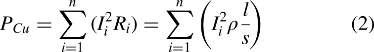
Where
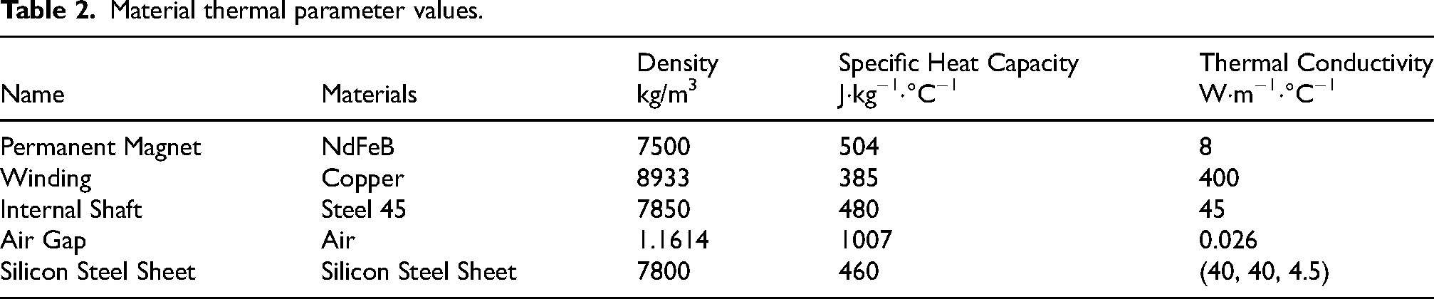
Thermal conductivity
The thermal conductivity coefficient serves as a measure of the thermal conductivity of an object, representing an inherent property that varies based on the object's type, ambient temperature, and other influencing factors. In the controllable electromagnetic hybrid magnetic coupler with an electromagnetic gap adjuster, all component materials, except for the silicon steel sheet, exhibit isotropic thermal conductivity. The silicon steel sheet is also isotropic, with its thermal conductivity values in the X, Y, and Z directions being 40, 40, and 4.5, respectively. In the analysis of transient temperature fields, it is necessary to define not only the thermal conductivity but also the material's density and specific heat capacity. These parameters are considered at room temperature. The values of the parameters mentioned above are considered to be their values at standard room temperature. Table 2 presents the thermal parameter values of the materials used for the components of the electromagnetic gap adjuster.
Material thermal parameter values.
Heat dissipation coefficient
When the electromagnetic gap adjuster is in operation, the main way of heat dissipation is convection heat dissipation with air, so it is crucial to analyze the convection heat dissipation coefficient. In the electromagnetic gap adjuster designed in this paper, the axial moving parts are moving, and the inner axis of the assembled permanent magnet is fixed, then the outer surface of the permanent magnet belongs to natural convection heat dissipation under the natural flow of air, and the formula of heat dissipation coefficient can be expressed as follows: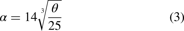
Where,
The convective heat dissipation coefficient on the air gap surface in an electromagnetic gap adjuster can be calculated from the following equation:
24
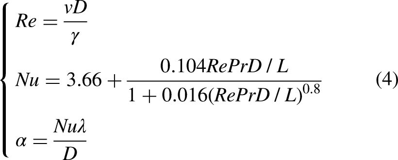
Where,
Development of electric-magnetic-thermal-stress coupling model
Relationship in electric-magnetic-thermal-stress coupling
The multi-physical field coupling simulation carried out in this paper mainly focuses on the core mechanism - electromagnetic gap adjuster, which works with multi-physical field coupling, and its electric-magnetic-thermal-stress coupling relationship is shown in Figure 3. Electromagnetic gap adjuster mechanism in the winding energized under the action of the magnetic field to produce Lorentz force, so that the axial moving parts through the connection key to drive the permanent magnet disk for axial movement, to achieve the function of speed regulation; electric and magnetic fields will produce Joule heat and eddy current effect, resulting in parts of the temperature rise; the temperature change will produce thermal stress, thermal stress is easy to lead to deformation of the material, cracking, fracture and other damages. It can be seen that the in-depth study of the device's complex electric-magnetic-thermal-stress coupling model is of great significance.
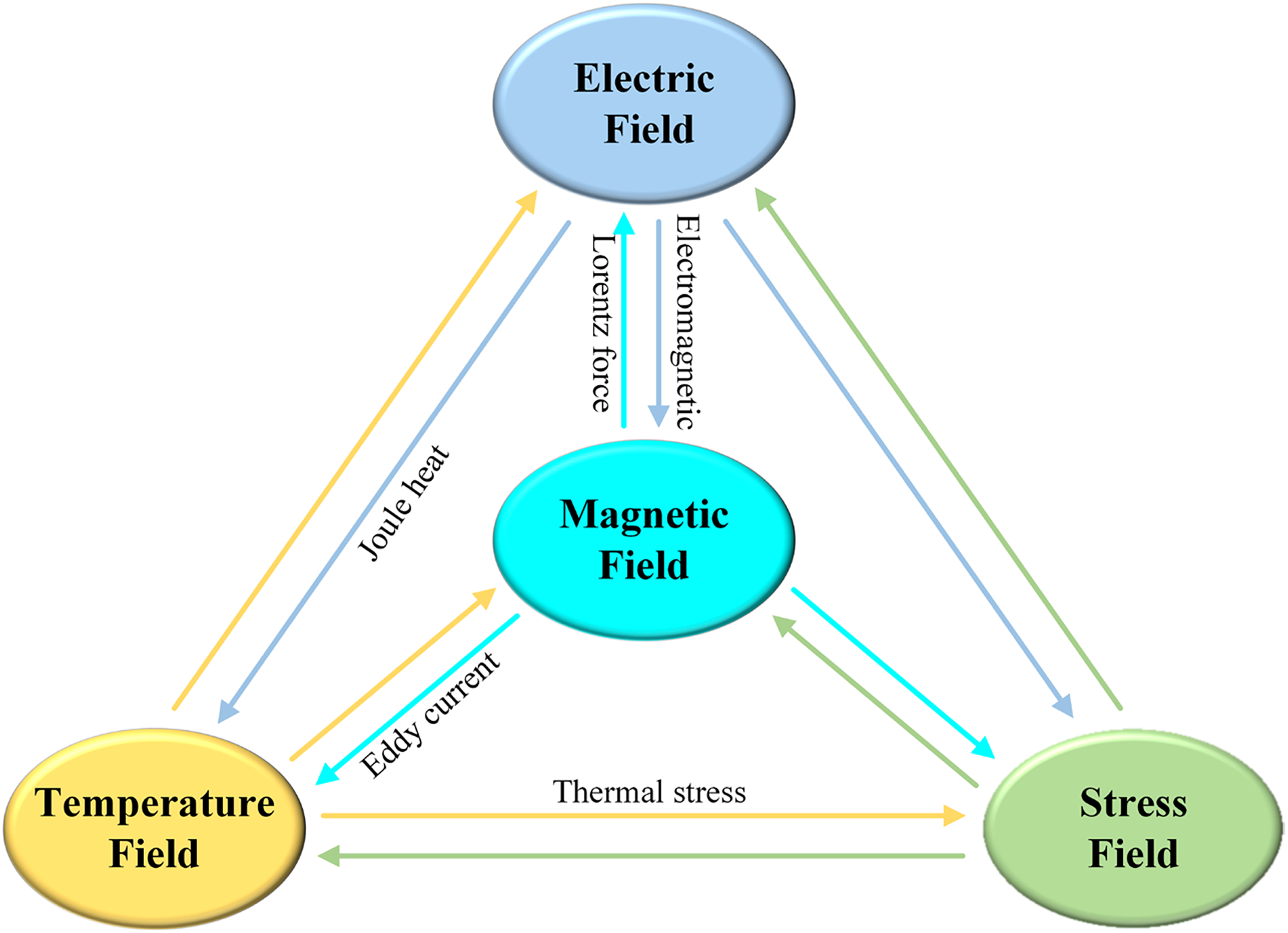
Electro-magnetic-thermal-stress coupling relationship in electromagnetic gap adjuster.
Process of simulation
The finite element simulation analysis of the electric-magnetic-thermal-stress coupling model of the controllable electromagnetic hybrid magnetic coupler begins with the establishment of a 3D model in SOLIDWORKS. This study specifically investigates the temperature rise and stress distribution of the electromagnetic gap adjuster within the magnetic coupler, focusing on its axisymmetric structure. To streamline calculations, 2D analysis module in Ansoft Maxwell is utilized. A 2D magnetic field analysis model is developed based on the initial 3D modeling. Subsequently, zero current excitation is applied to the permanent magnet, and the options “Set Eddy Effect” and “Set Coreless” are enabled for the relevant components to conduct the magnetic field analysis. After that, the electromagnetic field is linked with the temperature field via Workbench. The losses produced by the components serve as the heat source, which is then integrated into the steady-state and transient temperature field modules to derive the results of the temperature field analysis. Upon acquiring the results of the temperature field analysis, the temperature field is integrated into the static structure and transient structure modules of Workbench as the initial conditions. Optimal analysis outcomes can be achieved by configuring the appropriate materials and parameter values for each component. A diagram illustrating the simulation procedure for the analysis of the controllable electromagnetic hybrid magnetic coupler's electric-magnetic-thermal-stress coupling is presented in Figure 4.
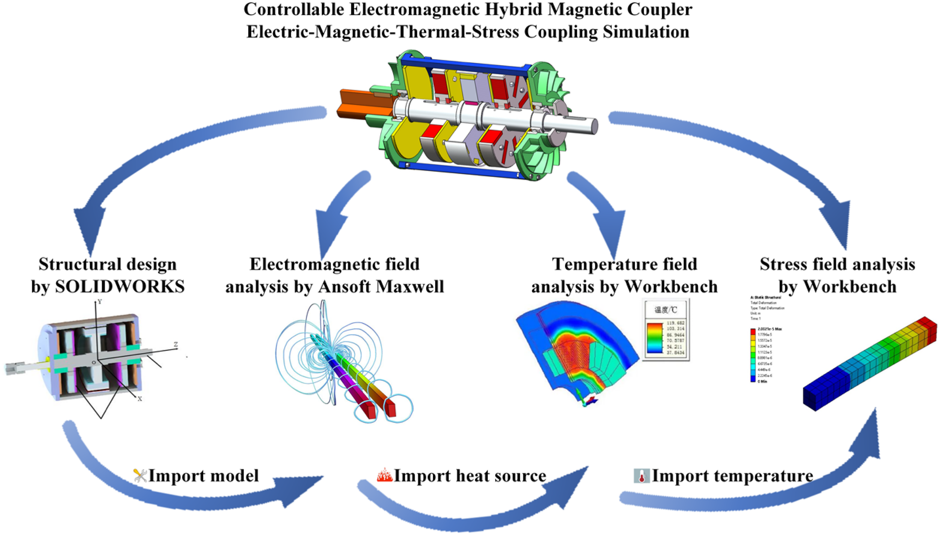
Schematic of simulation process.
Simulation results and analysis
According to the axisymmetric structure of the designed electromagnetic gap adjuster, a 2D finite element analysis method can be adopted to increase the calculation efficiency without affecting the calculation results. Select transient field analysis in Maxwell to establish a 2D model as shown in Figure 5. Among them, the width of the permanent magnet, the length of the air gap between the winding and the permanent magnet, the number of turns of the coil, and the depth of the winding slot are parameterized in order to obtain the optimal structural parameters by changing the values of each parameter and analyzing and discussing different results. In the electric-magnetic field coupling analysis, in addition to setting the material, boundary conditions, etc., it is also necessary to refine the mesh for the windings, permanent magnets and other important parts, and finally set the solution time to 1 s, and the time step is set to 0.01 s. After the simulation and analysis, the cloud diagram of the magnetic density distribution of the electromagnetic gap adjuster is shown in Figure 6, and the maximum magnetic density is 2.7 T.
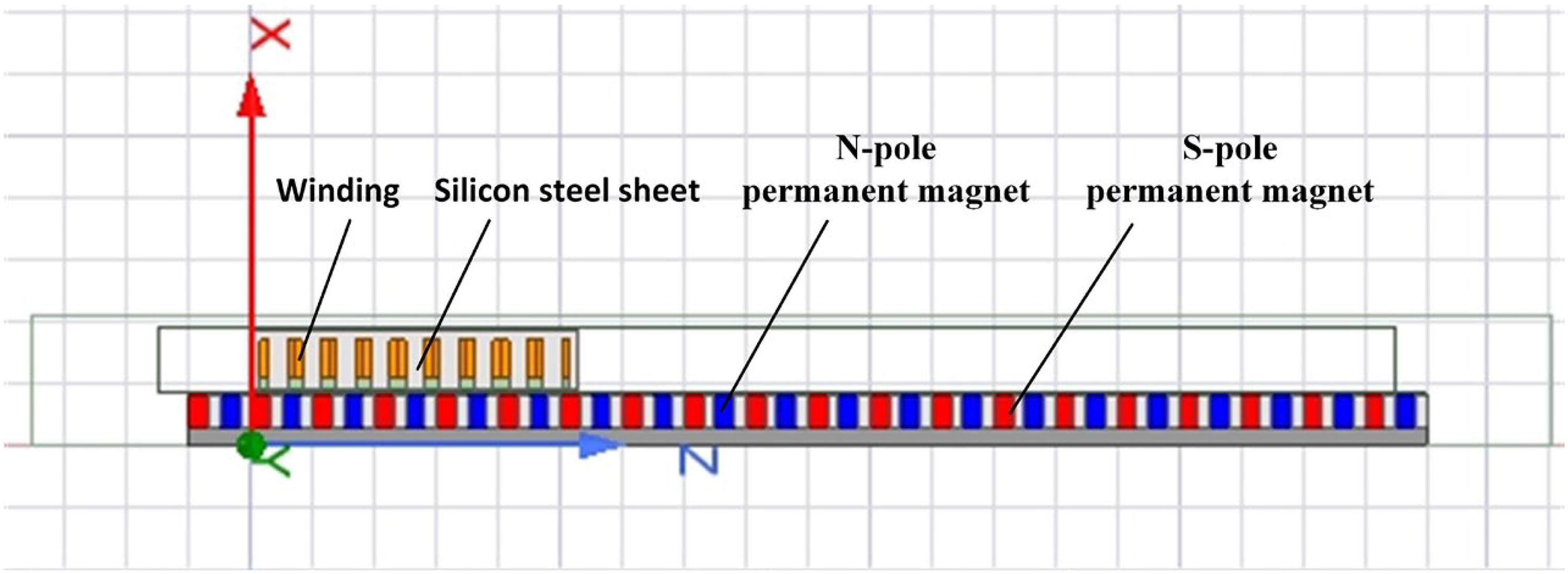
2D model of electromagnetic gap adjuster.
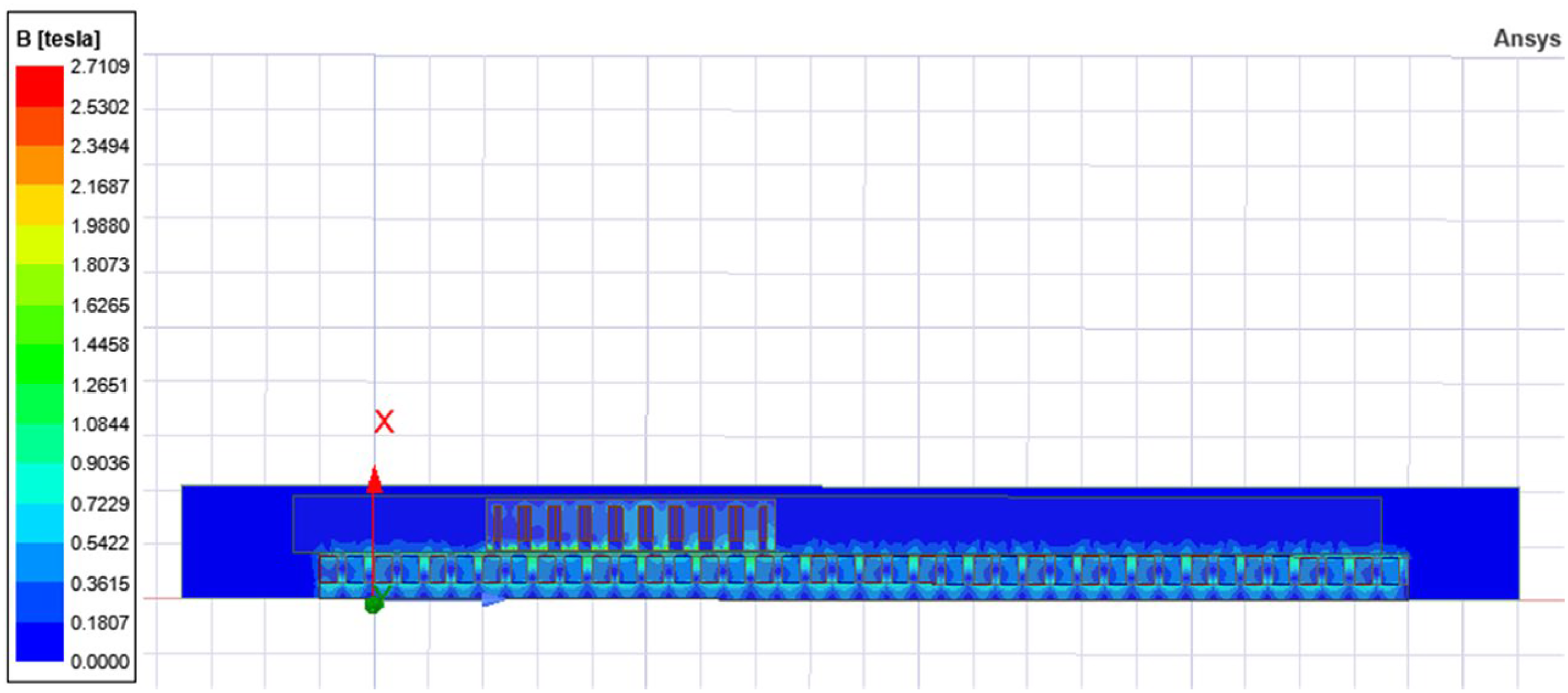
Cloud view of the magnetic density distribution of the electromagnetic gap adjuster.
Analysis by Maxwell simulation software, it is possible to determine the different loss values associated with each component. These values are subsequently incorporated into the temperature field as a heat source and examined as an initial condition. In this study, the environmental temperature is set at 22 °C. The permanent magnet has a width of 5 mm, the air gap length is 1 mm, the winding slot depth is 8 mm, and the coil consists of 14 turns. These parameter combinations were selected, and the optimized iron loss and eddy current loss curves are presented in Figure 7 post-processing. From the loss curve, the iron loss is approximately 6.8 mW and the eddy current loss at the permanent magnet is approximately 4 μW when the electromagnetic gap adjuster operates steadily.
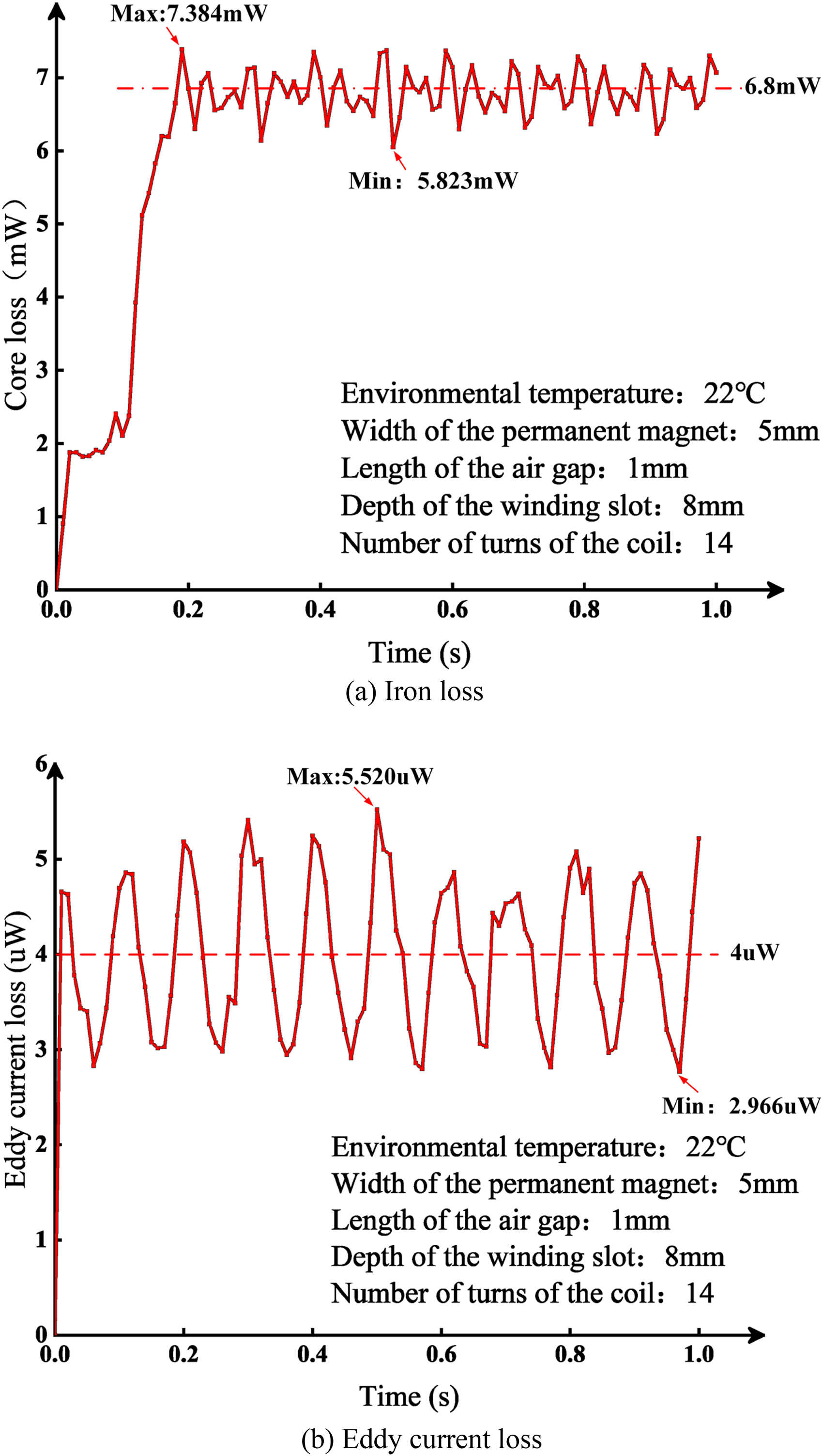
Loss curve.
Maxwell is coupled with the temperature field module through Workbench, and after importing the geometric model and the heat source, the corresponding material parameters and boundary conditions can be set; similarly, the analysis results of the temperature field are also imported into the structural field as the initial conditions to be analyzed, and the setup of the joint simulation module of electric-magnetic-thermal-stress is shown in Figure 8. The meshing of the temperature field and structural field is shown in Figure 9, where the number of cells is 6695 and the number of nodes is 8366.
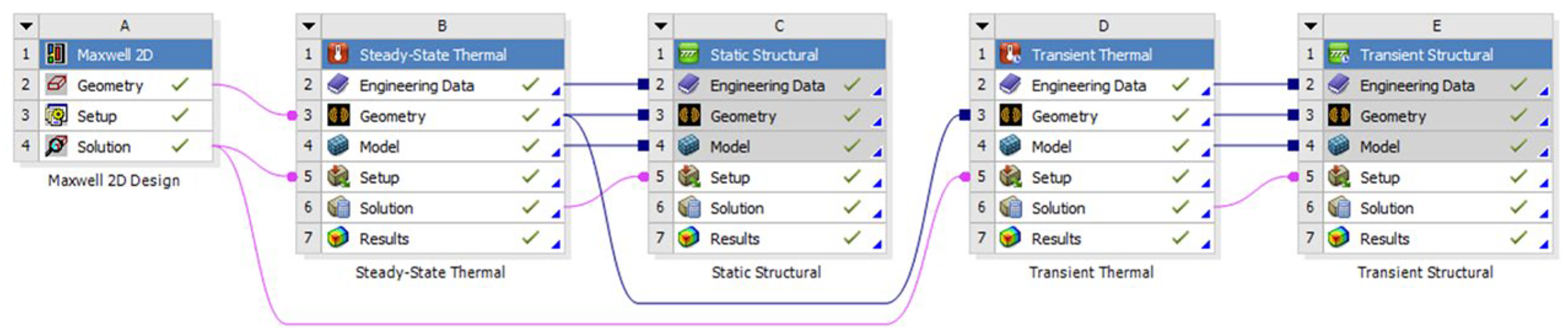
Module setup for joint simulation of electro-magnetic-thermal-stress coupling.
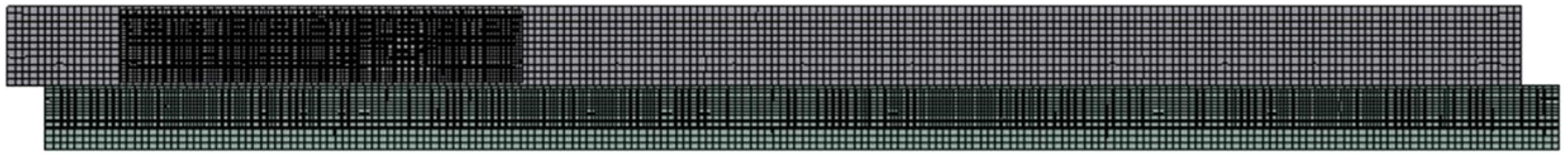
Mesh division.
The environmental temperature is established at 22 °C. The heat loss introduced by Maxwell is utilized as the primary heat source, the analysis time is set to 1 s, and the convective heat transfer coefficient is adjusted to achieve the steady-state temperature field. Additionally, the transient temperature field simulation results are illustrated in Figure 10.
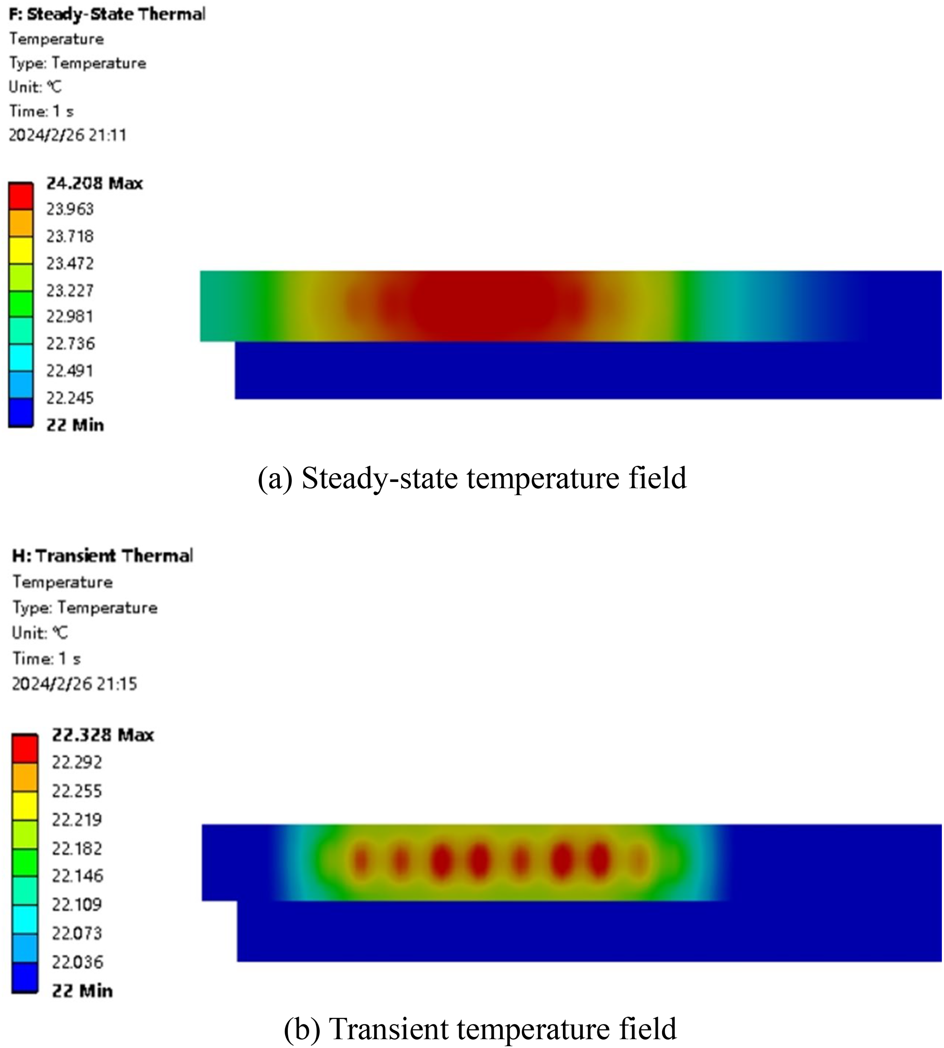
Temperature field simulation contour maps.
The temperature field simulation results reveal that the area with the highest temperature rise is predominantly concentrated in the winding section. This observation aligns with the theoretical assertion that the loss in the coil winding segment contributes the most to the overall loss, as discussed in the loss analysis section. This correspondence underscores the precision of the simulation outcomes. Typically, the operational temperature for permanent magnet NdFeB material should not exceed 80 °C. The simulation results indicate that the maximum temperature of the steady-state field is 24.208 °C, while the maximum temperature of the transient field is 22.328 °C. These temperatures are significantly below the critical threshold, ensuring safe operation. The fluctuation in temperature frequently induces thermal stress. The outcomes of the temperature field simulation are integrated into the structural field for the analysis of thermal stress variations (Figure 11), depicting the equivalent stress distribution of the device.
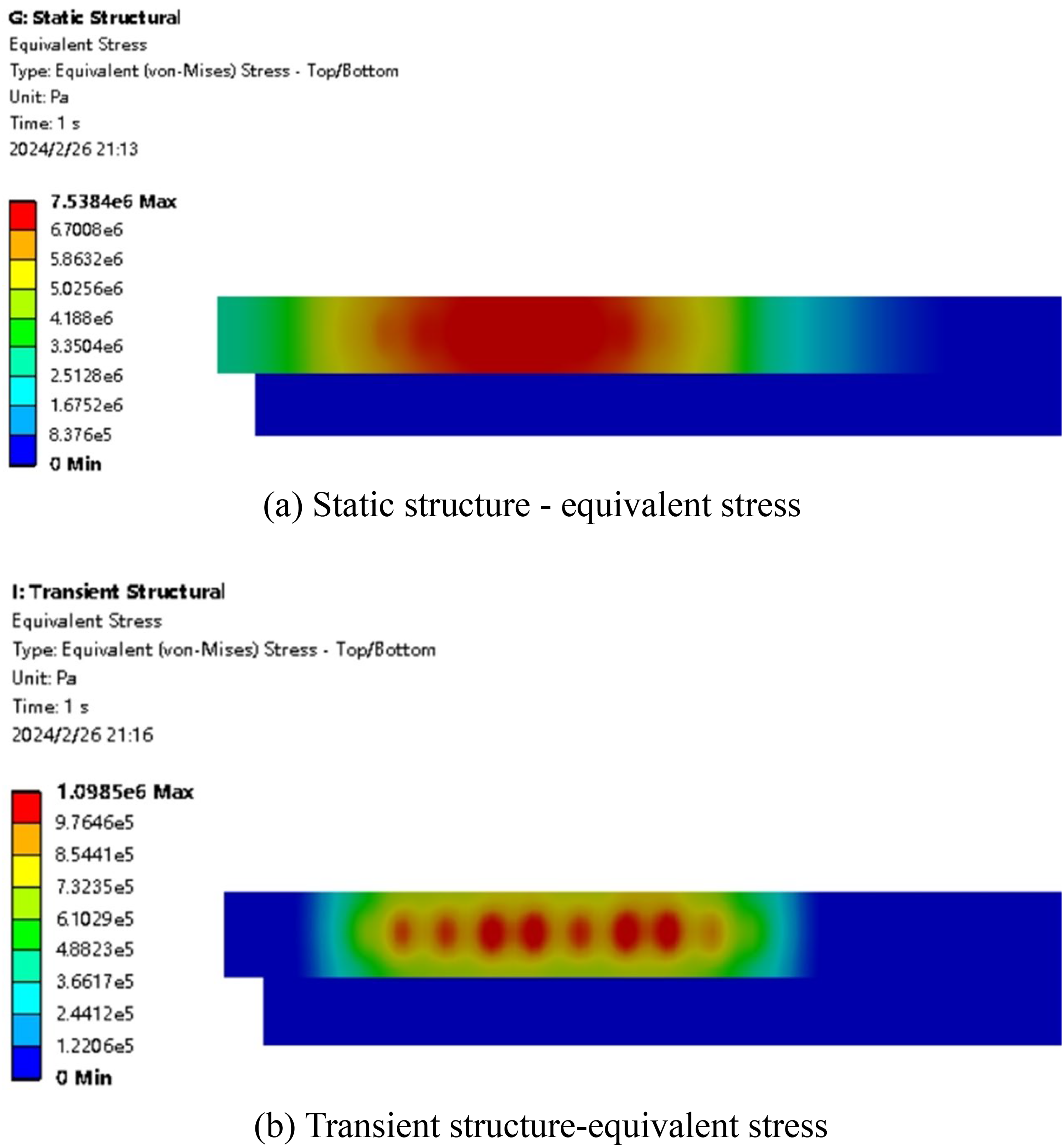
Simulation results of stress field.
Thermal stress may lead to deformation and displacement of the windings, etc., which will cause the mechanical structure to lose its original stability and accuracy; thermal stress at high temperatures will also reduce the endurance of the material, resulting in local deformation or even damage to the structure; the presence of thermal stress may also limit the operating temperature range and service life of the designed electromagnetic gap adjuster. The equivalent stress simulation results indicate that the thermal stress predominantly accumulates in the winding section, aligning with the outcomes of the temperature field simulation. The coil winding primarily consists of copper, with a typical permissible stress of 70∼100 MPa, while the maximum equivalent stress is 7.538 MPa, falling within the permissible stress range. In conclusion, the temperature field and stress field of the electromagnetic gap adjuster, characterized by a parameter combination including a 5 mm width of the permanent magnet, 1 mm length of the air gap, 8 mm depth of the winding slot, and 14 turns of the coil, conform to the operational specifications and achieve the intended design goals.
Effect of permanent magnet width on coupled model
The environmental temperature is maintained at 22°C. The air gap between the winding and the permanent magnet is set at 1 mm, the depth of the winding slot is 8 mm, and the coil consists of 14 turns. The width of the permanent magnet is varied to investigate the temperature field and stress field evolution under different widths of the permanent magnet. The correlation between the width of the permanent magnet and the temperature increase of the device is illustrated in Figure 12, while the association between the width of the permanent magnet and the stress of the device is depicted in Figure 13.
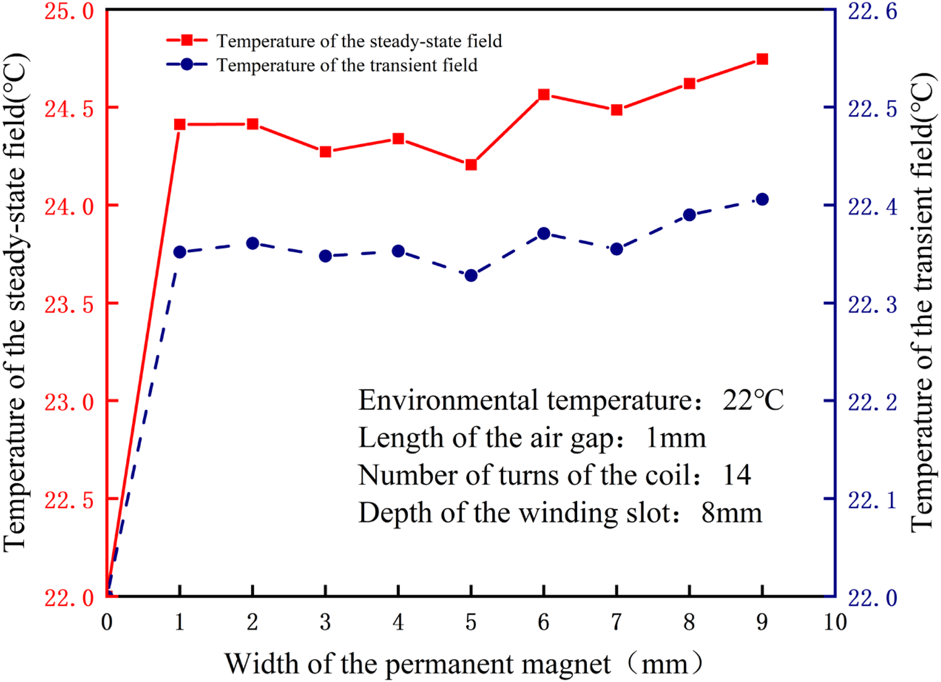
Relationship between permanent magnet width and temperature rise.
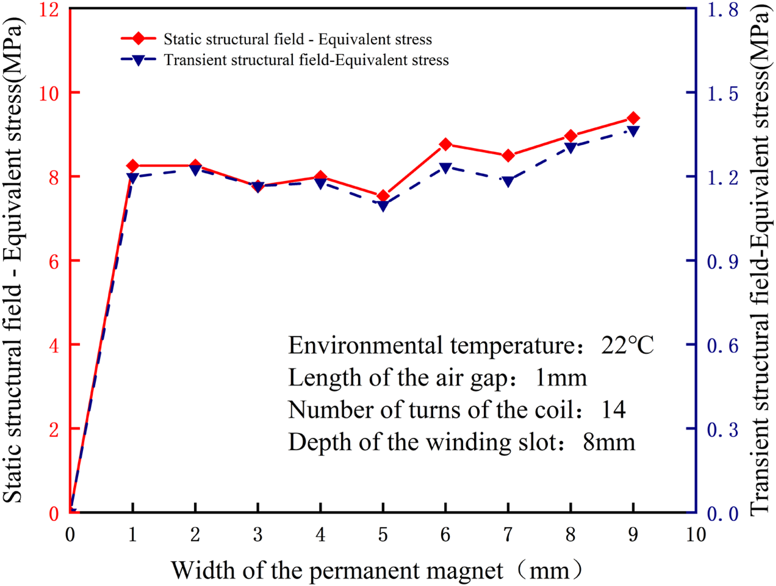
Relationship between permanent magnet width and stress.
In Figures 12 and 13, the temperature and stress evolution patterns resulting from variations in the width of the permanent magnet exhibit similarities. As the width of the permanent magnet increases, both temperature and stress demonstrate a consistent upward trajectory, albeit with minor fluctuations in the intermediate range. When the width of the permanent magnet is 9 mm, the steady-state field temperature reaches 24.746 °C, and the static structural field's equivalent stress reaches 9.387 MPa. Conversely, when the width of the permanent magnet is reduced to 5 mm, the temperature rise is minimized, with the steady-state field temperature measuring 24.206 °C.
Effect of air gap length on coupled model
The environmental temperature is maintained at 22 °C. The permanent magnet has a width of 5 mm, the winding slot has a depth of 8 mm, and the coil consists of 14 turns. The experiment involves varying the air gap between the winding and the permanent magnet to investigate the effect of different air gap lengths on the integrated electric-magnetic-thermal-stress model. Figure 14 elucidates the relationship between the air gap length and the device's temperature rise, whereas Figure 15 delineates the correlation between the air gap length and the stress experienced by the device.
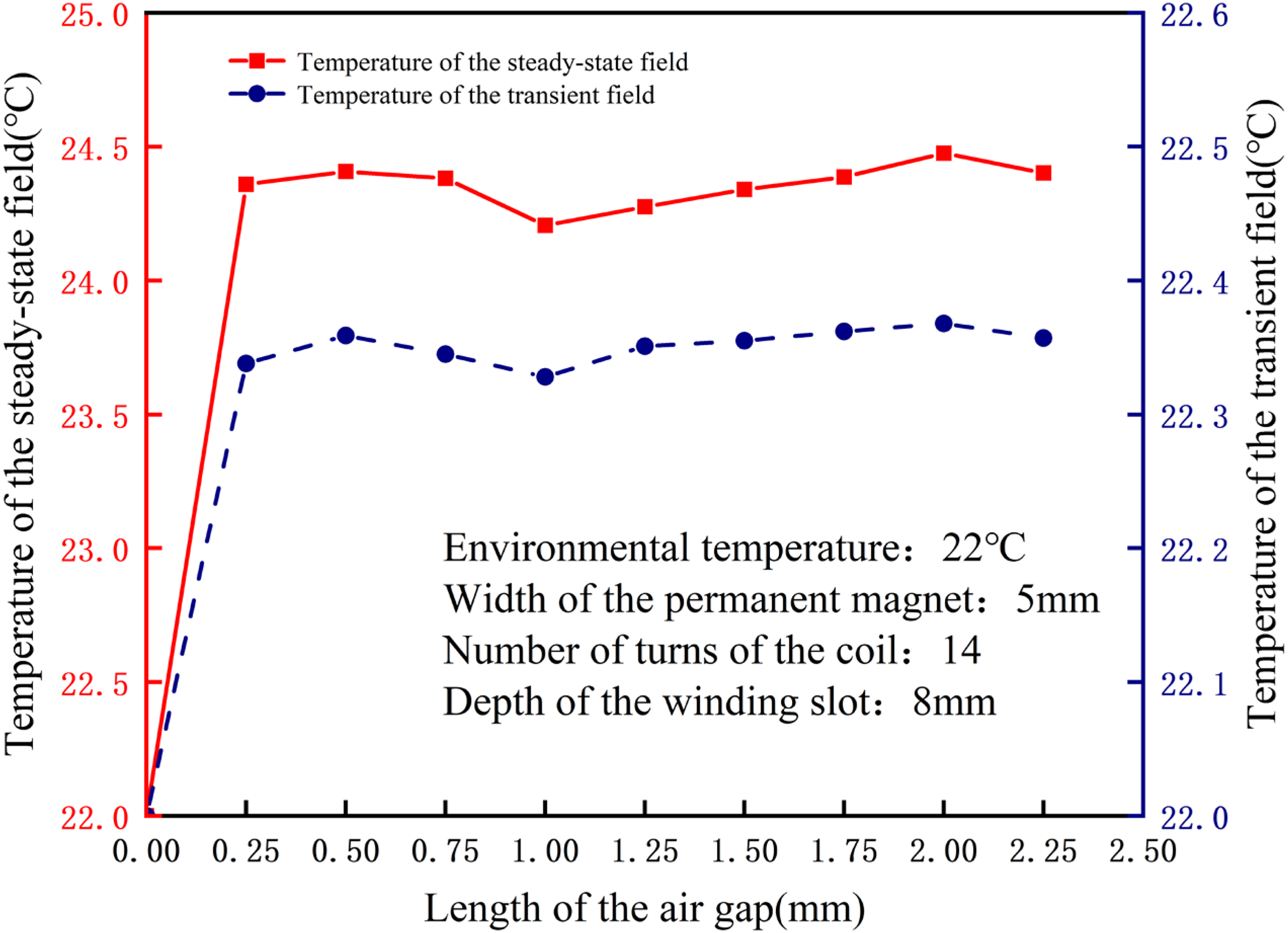
Relationship between air gap length and temperature rise.
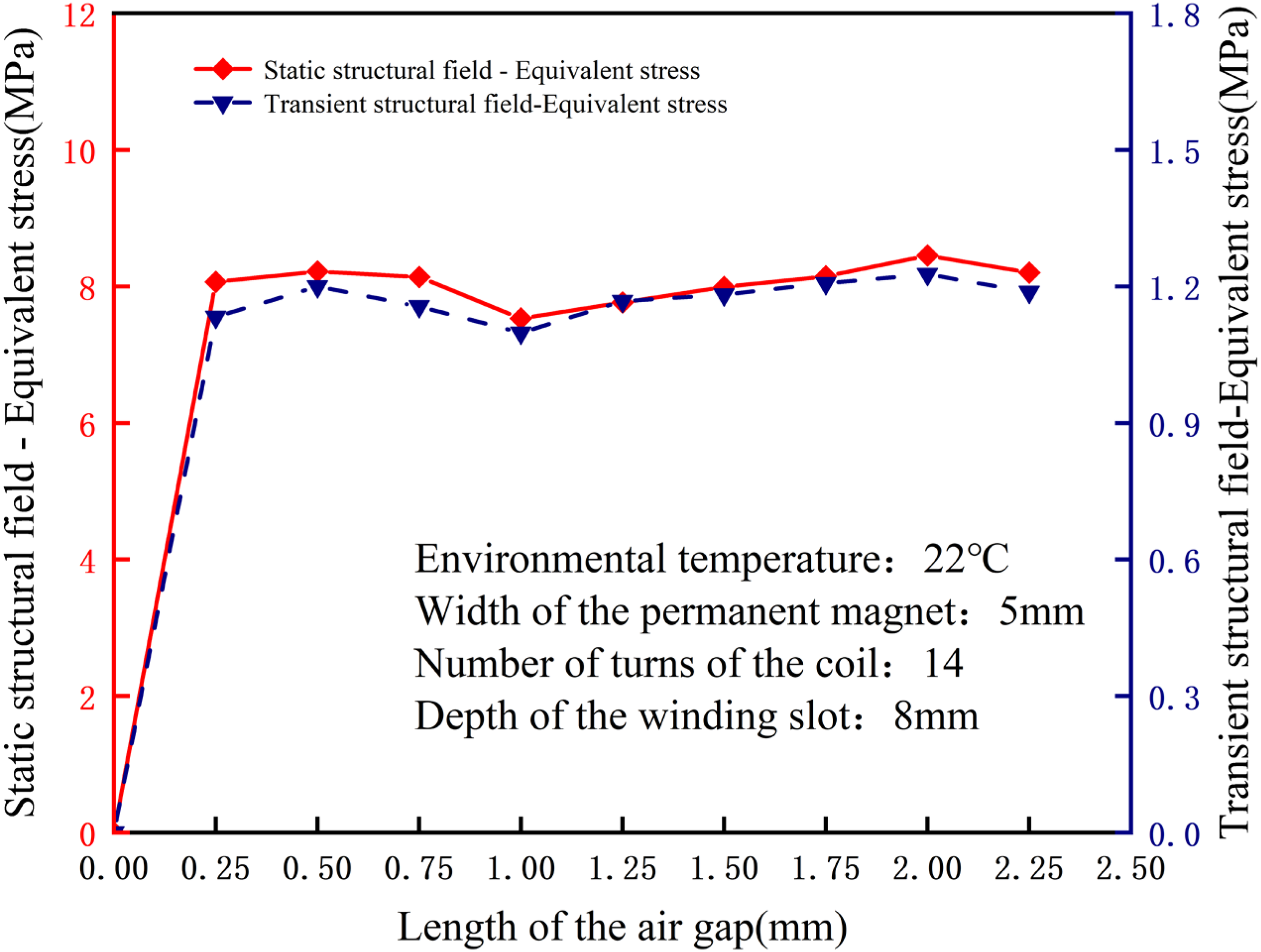
Relationship between air gap length and stress.
The relationship curve depicting the effect of the length of the air gap on the temperature rise and stress of the device exhibits fluctuations. As the length of the air gap between the windings and the permanent magnets increases, the temperature and stress do not consistently increase. The temperature rise and stress of the device reach their peak when the length of the air gap is 2 mm. At this point, the temperature of the steady-state field is 24.476 °C, and the equivalent stress of the static structural field is 8.455 MPa. Conversely, the temperature rise and stress are minimized when the length of the air gap is 1 mm, resulting in the device experiencing the least amount of temperature rise and stress. It is crucial to carefully determine the distance between the winding and the permanent magnet. This decision should not solely prioritize achieving low loss and low temperature rise but should also take into account whether Lorentz force acting on the axial moving parts is within the necessary parameters to facilitate the gap adjustment function.
Effect of winding slot depth on coupling model
The environmental temperature is maintained at 22 °C, with the permanent magnet width set at 5 mm, the coil wound with 14 turns, and the air gap length at 1 mm. Observations of temperature and stress variations in the device are conducted at various depths within the winding slots. The correlation between the depth of the winding slot and the temperature rise of the device is presented in Figure 16, while the association between the depth of the winding slot and the stress of the device is shown in Figure 17.
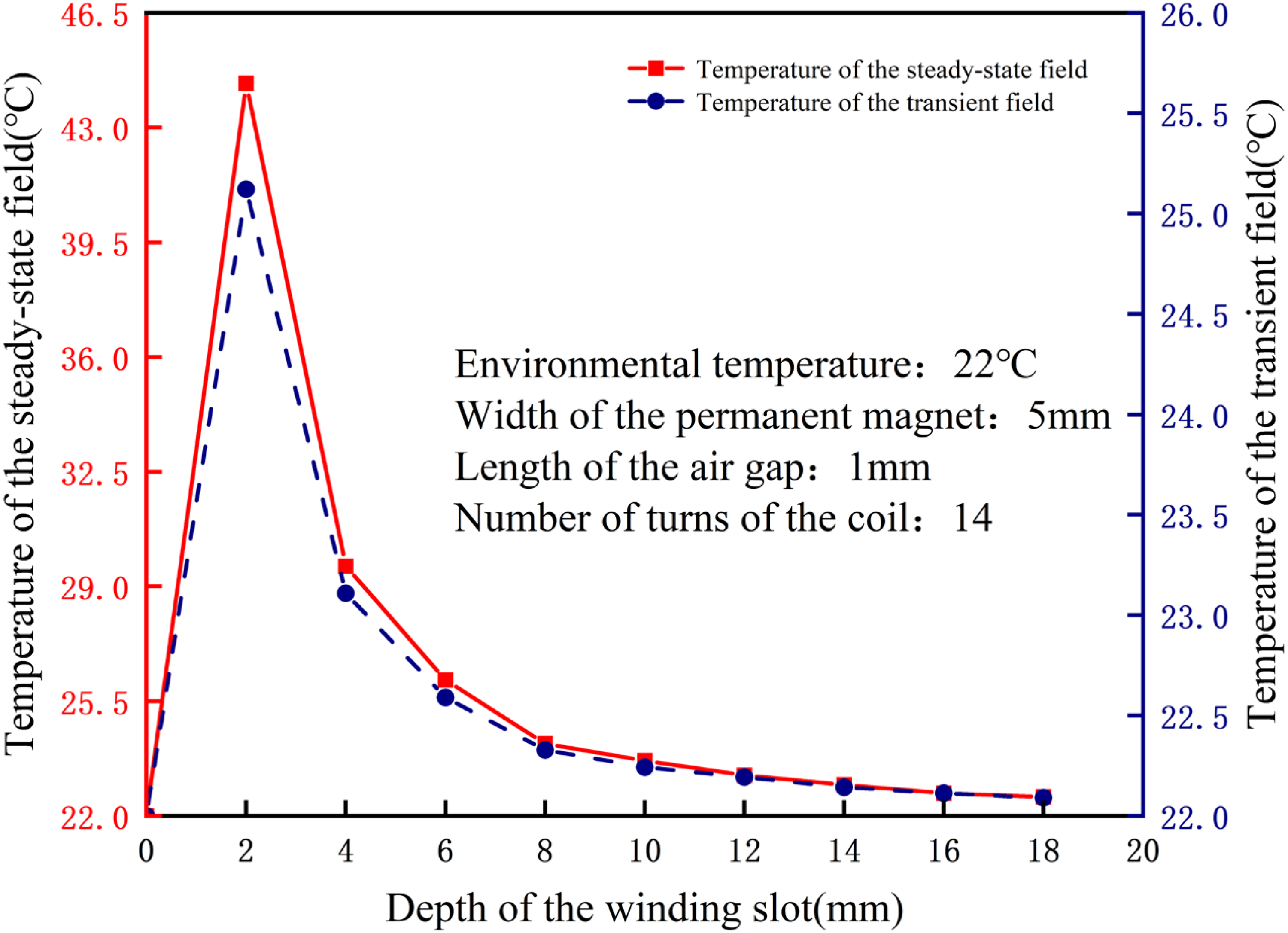
Relationship between winding slot depth and temperature rise.
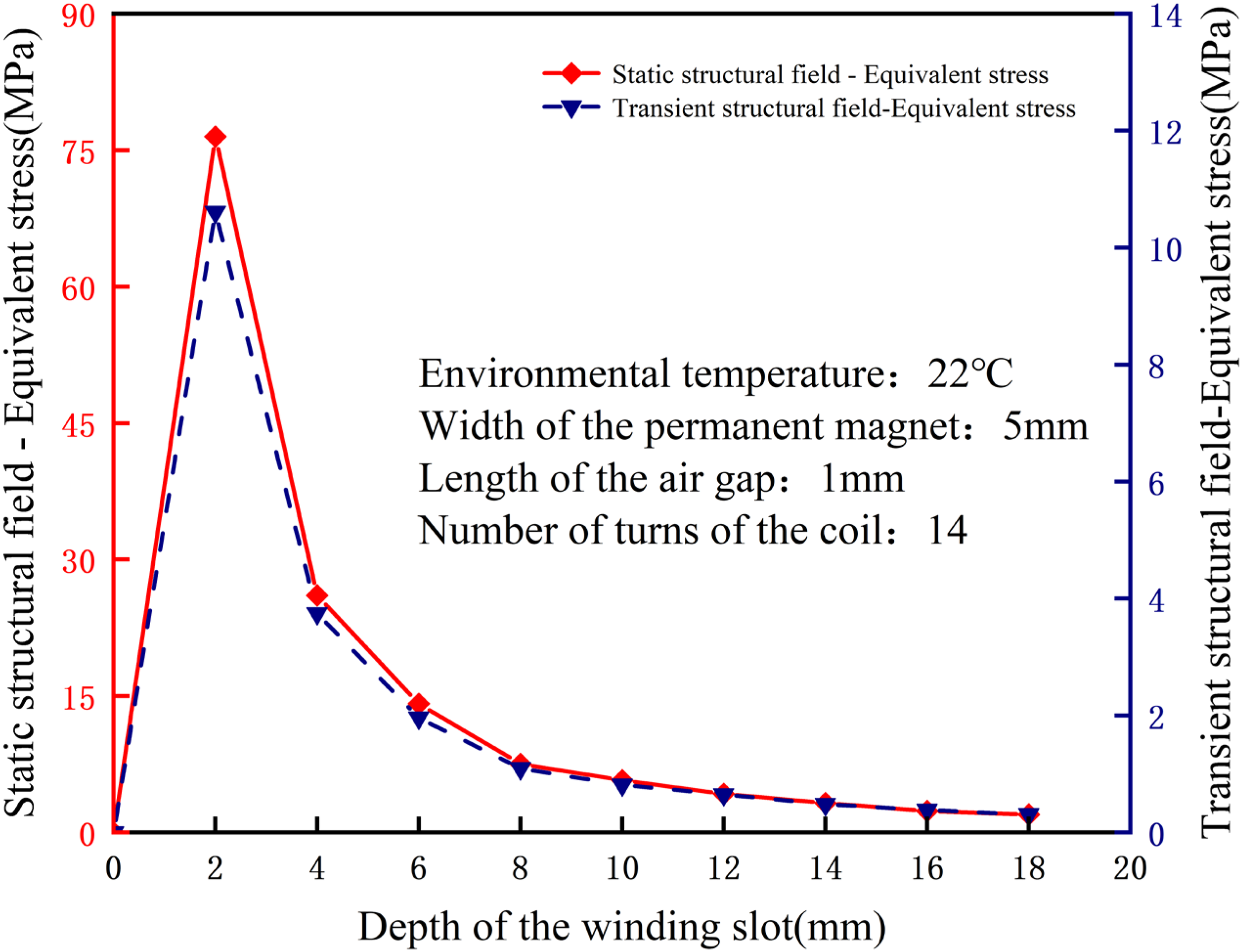
Relationship between winding slot depth and stress.
The temperature and stress variations of the device resulting from alterations in the depth of the winding slot are more pronounced (Figures 16 and 17). When the slot depth measures 2 mm, the steady-state field temperature reaches 44.353°C, and the static structural field stress reaches 76.492 MPa. Upon reaching a depth exceeding 2 mm, the temperature and stress levels of the device decrease as the slot depth increases. When the depth of the winding slot is insufficient, the coils become densely packed, leading to heat accumulation and challenges in dissipation. Conversely, an excessively deep winding slot results in increased structural size and space occupation. Therefore, it is crucial to ensure a well-thought-out design of the winding slot depth.
Effect of coil turns on coupling model
The environmental temperature is maintained at 22 °C. The permanent magnet has a width of 5 mm, the winding slot has a depth of 8 mm, and the air gap length is 1 mm. The study aims to observe the temperature and stress variations in the coupling model under different coil turns. Figure 18 presents the relationship between the number of coil turns and the device's temperature elevation, while Figure 19 highlights the link between the coil turn count and the stress imposed on the device.
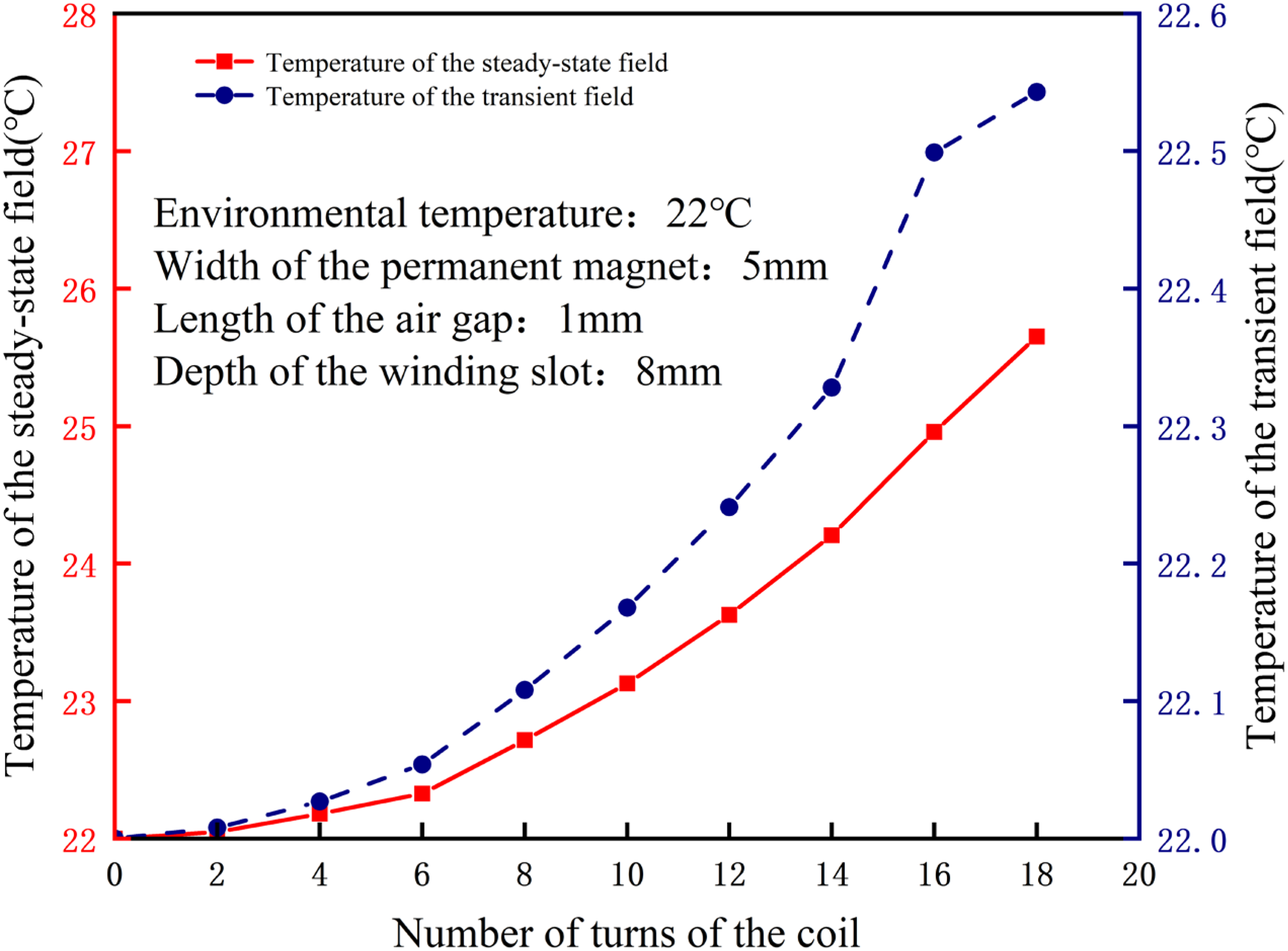
Relationship between coil turns and temperature rise.
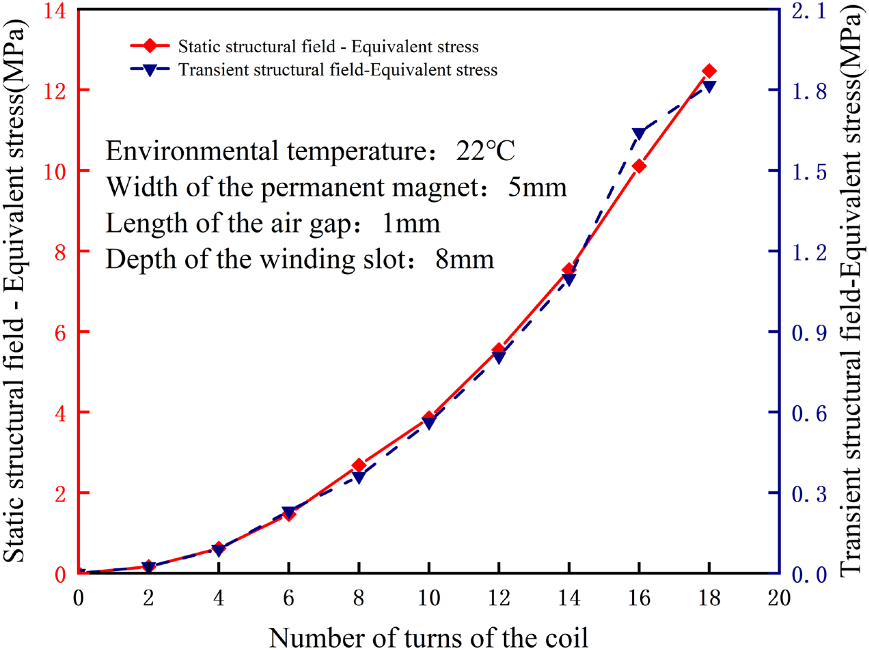
Relationship between coil turns and stress.
The relationship curve depicting the number of turns of the coil against the temperature rise and stress of the device illustrates that as the number of turns of the coil increases, the Joule heat generated and subsequent loss also increase. Consequently, the temperature and stress experienced by the device escalate accordingly. When the coil has 18 turns, the steady-state field temperature reaches 25.652 °C, and the equivalent stress of the static structural field reaches 12.468 MPa. There is a continuous tendency for these values to increase, highlighting the importance of carefully selecting the number of turns. This selection is crucial to meet the required thrust for the axial gapping function while preventing excessive losses.
Simulation data
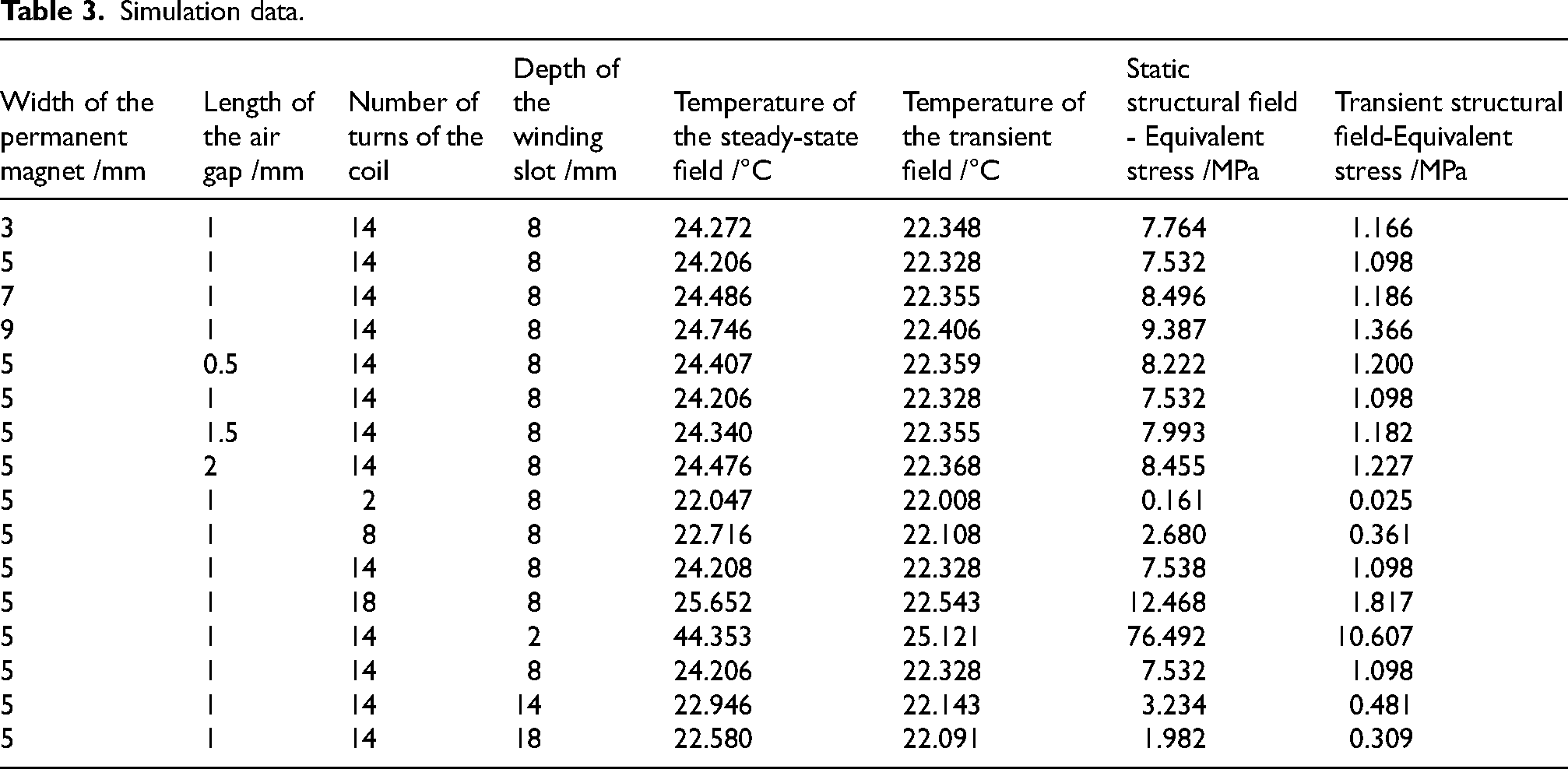
The study examines the effect of four fundamental parameters: the width of the permanent magnet, the length of the air gap between the winding and the permanent magnet, the number of turns of the coil, and the depth of the winding slot, on the temperature rise and stress of the device through parametric design. The simulation data for selected temperatures and stresses are presented in Table 3. When the permanent magnet's width measures 5 mm, the air gap's length is 1 mm, the coil has 14 turns, and the winding slot's depth is 2 mm, the device experiences maximum temperature rise and stress. At this point, the steady-state field temperature reaches 44.353 °C, and the static structural field's equivalent stress is 76.492 MPa. The shallow depth of the winding slot leads to increased eddy current loss and current density, influencing heat dissipation and causing heat accumulation. When the permanent magnet's width measures 5 mm, the air gap's length is 1 mm, the coil has 2 turns, and the winding slot's depth is 8 mm, the device experiences minimal temperature rise and stress. At this configuration, the steady-state field temperature is 22.047 °C, and the static structural field's equivalent force is 0.161 MPa. A decrease in the number of coil turns results in reduced losses; however, it can weaken the magnetic field strength, influencing the device's ability to perform its intended function within the normal gap range.
Simulation data.
Parameter optimization of electromagnetic gap adjuster based on orthogonal experiment method
Orthogonal experimental design
Previously, a single parameter analysis was carried out for the four key parameters of the electromagnetic gap adjuster, namely, the width of permanent magnet, the length of air gap, the depth of winding slot and the number of turns of coil. However, the electromagnetic gap adjuster is a complex electromechanical system, and the parameters do not exist in isolation, but are coupled and influenced by each other. Therefore, single parameter analysis can not fully and accurately reflect the comprehensive influence of multiple parameters on the heat generation temperature of the mechanism. In order to overcome this limitation, the orthogonal experiment method is introduced to optimize the structural parameters of the electromagnetic gap adjuster, so as to determine the optimal parameter combination, so as to effectively reduce the temperature rise of the mechanism.
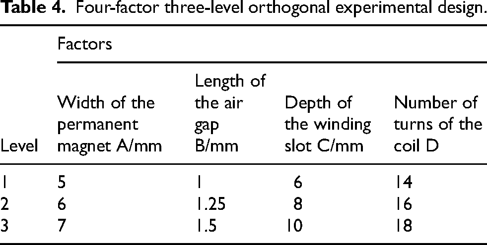
The four factors of permanent magnet width (A), air gap length (B), winding groove depth (C) and coil turns (D) were selected for investigation. According to the research basis of the above parameter analysis and the actual engineering requirements, the appropriate value range of each factor was divided and set to three levels. The L9(34) orthogonal table was selected, as shown in Table 4.
Four-factor three-level orthogonal experimental design.
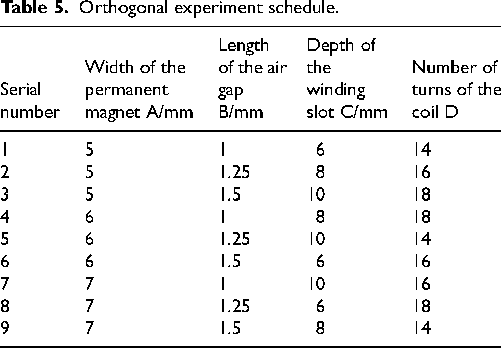
The analysis is carried out according to the experimental combination of L9(34) orthogonal table, which indicates that the experiment has a total of 4 factors and 9 groups of experimental combinations. In general, 81 experiments are required for the comprehensive experiment of four factors and three levels. However, according to the characteristics of the orthogonal experimental method, which is comprehensive, balanced and dispersed, and neatly comparable, the nine groups of experiments of L9(34) orthogonal table, The actual situation can be fully and accurately reflected. The specific experimental plan is shown in Table 5.
Orthogonal experiment schedule.
Orthogonal experiment results and analysis
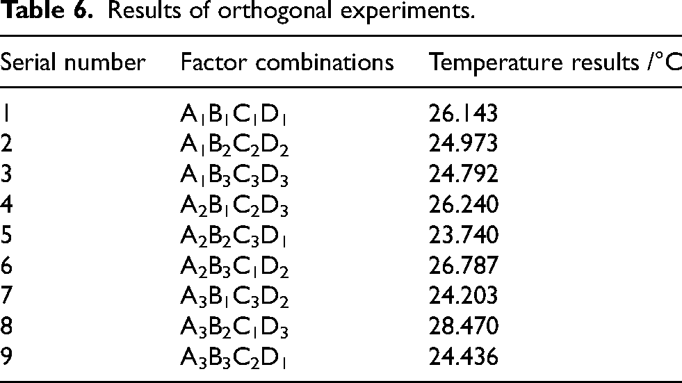
The multi-group coupling simulation of the electromagnetic gap adjuster was carried out through the orthogonal experiment schedule, and the temperature results under different conditions were obtained, and the data of each group were sorted out as shown in Table 6. At the same time, in order to explore the specific influence of various factors on the temperature rise of the mechanism, the range analysis of the experimental results was carried out, as shown in Table 7.
Results of orthogonal experiments.
Range analysis.
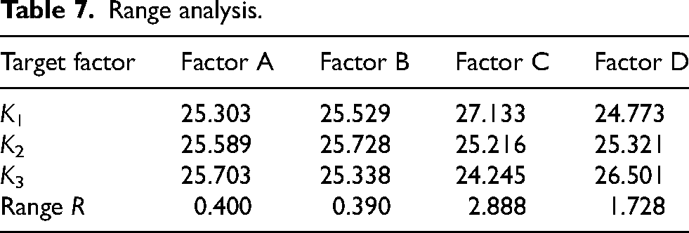
According to the analysis of the data in Table 7, it can be seen that the order of influence on the temperature rise of the electromagnetic clearance adjusting mechanism is C > D > A > B. Factor C (winding slot depth) has the largest range and is the main factor affecting the temperature rise of the mechanism, while A, B and D are the secondary factors. In order to further accurately judge the significance of each factor, ANOVA was performed on the temperature rise of the mechanism with factor B as the error item, and the analysis results were shown in Table 8.
Analysis of variance.
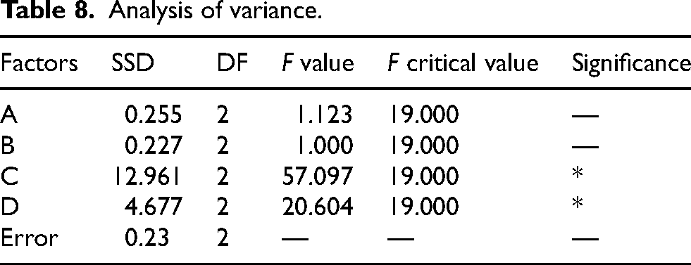
According to the ANOVA in Table 8, factors C and D have significant influence on the experimental results, while factors A and B have no significant influence. According to the range analysis in Table 7, the optimal combination is A1B3C3D1, that is, when the permanent magnet width is 5 mm, the air gap length is 1.5 mm, the winding slot depth is 10 mm, and the number of turns of the coil is 14, the temperature rise of the electromagnetic gap adjuster is minimum under the premise of meeting the working conditions. According to this condition, the steady-state field temperature of the mechanism rises to 23.689 °C.
Conclusion
In response to the challenges posed by the gapping mechanism of adjustable-speed type magnetic couplers, characterized by issues such as large volume and imprecise air gap adjustment, a novel controllable electromagnetic hybrid magnetic coupler is introduced. This innovative coupler enables precise gapping between the conductor rotor and the permanent magnet rotor through electromagnetic gapping techniques.
The design of a novel controllable electromagnetic hybrid magnetic coupler is based on the principle of electromagnetic induction with a variable air gap. By energizing the wires, the axial moving parts will be displaced along the axial direction due to Lorentz force within the magnetic field produced by the permanent magnets. By altering the electric current's direction, reciprocating motion can be achieved, allowing for precise adjustment of the air gap between the copper conductor disks and the permanent magnets. To develop a coupled electric-magnetic-thermal-stress model for the electromagnetic gap adjuster, it is necessary to construct a simulation platform for multi-physical field coupling. This simulation platform will enable the investigation of various parameters such as the width of the permanent magnet, the length of the air gap, the depth of the winding groove, and the number of turns of the coil within the device, considering variations in temperature and stress. When the width of the permanent magnet is 5 mm, the length of the air gap is 1 mm, the number of turns of the coil is 14, and the depth of the winding slot is 2 mm, the device reaches its maximum temperature rise and stress values. At this point, the temperature of the steady-state field is 44.353 °C, and the equivalent force of the static structural field is 76.492 MPa. Conversely, when the width of the permanent magnet remains at 5 mm, the length of the air gap is 1 mm, the number of turns of the coil is 2, and the slot depth of the winding is 8 mm, the temperature rise and stress are minimized. Under these conditions, the temperature of the steady-state field is 22.047 °C, and the equivalent stress of the static structural field is 0.161 MPa. Through the electric-magnetic-thermal-stress coupling in the electromagnetic gap adjuster revealed that the significant temperature rise and stress concentration primarily occur in the winding section, aligning with the theoretical analysis results. This serves as a foundation for advancing the understanding of controllable electromagnetic hybrid magnetic drive technology and establishing the parameters for electromagnetic gapping. Through the analysis of a three-level orthogonal experiment with four factors, it is known that the order of influence on the temperature rise of the electromagnetic gap adjuster is: winding slot depth > coil turns > permanent magnet width > air-gap length. Moreover, when the permanent magnet width is 5 mm, the air-gap length is 1.5 mm, the winding slot depth is 10 mm, and the coil turns are 14, the steady-state field temperature rise of this mechanism is the lowest, at 23.689 °C.
Footnotes
Acknowledgements
This work is supported in part by the National Natural Science Foundation of China under Grant (No.52274152, 52404160), in part by the Natural Science Outstanding Youth Research Foundation of Anhui Province under Grant (No. 2308085Y37), in part by the Research Project of Outstanding Youth in Universities of Anhui Province under Grant (No. 2022AH020056).
Funding
The author(s) received no financial support for the research, authorship, and/or publication of this article.
Declaration of conflicting interests
The author(s) declared no potential conflicts of interest with respect to the research, authorship, and/or publication of this article.