
Abstract
Linear machines with high thrust force and low thrust ripple are essential for linear direct-drive applications. The transverse flux machines gain the advantage of high force density by decoupling of electric and magnetic loadings. However, there exists high thrust ripple defecting its performance. This paper investigates thrust ripple of a dual-PM transverse flux linear machine (TFLM) with permanent magnets on both primary and secondary sides. The causes resulting in the thrust ripple is presented and analyzed, including the detent force, the reluctance force and the harmonic force. The 3-D finite element method is employed to evaluate the electromagnetic performance. Furthermore, the suppression technologies of both pole shifting and skewing of secondary side are estimated to reduce the thrust ripple of the dual-PM TFLM.
Introduction
Linear machines have the capability to drive the load via rectilinear motion directly without any intermediate conversion devices when compared to its rotary counterpart.1,2 Hence, the linear machine drive system can benefit from high speed, high accuracy, high reliability, low maintenance costs and no centrifugal force. As is well known, the electric loading and magnetic loading compete for the effective space in the machine. In order to improve the thrust force, either the electric loading or magnetic loading should be increased. However, the heat dissipation of the machine limits the highest current density available, while the saturation effect of the iron limits the available flux density. Therefore, further improve the force density is not an easy case for conventional linear machines. Recently, the transverse flux topologies have the peculiarity of decoupling of electric and magnetic loadings, and the force density can be further improved by decreasing the pole pitch.3,4 The transverse flux linear machines (TFLM) integrate the high force density feature by adopting transverse flux topologies and the direct-drive feature of linear machines. Hence, the TFLMs seem to be a potential alternative for low speed linear-direct-drive applications. Numerous TFLMs have been proposed in literature including flat type5–9 and cylindrical type,10–13 single-side structure and double-side structure,14–17 surface PM type and flux-gathering type.
Thrust ripple exists generally in linear machines, and it defects the performance of the linear machines. Chang et al. developed and investigated a double-side TFLM with flux-gathering mover. 18 The resultant thrust force density is 40 kN/m2, which is rather high than the conventional linear machine. But the TFLM has much cogging pulsation in the force profile since it was designed as a single-phase structure. Many TFLMs have been designed as multi-phase configurations to improve the thrust force and suppress the force ripple. Zou et al. proposed a tubular TFLM with circumferential three-phase structure distribution and the stator laminations are similar to the conventional rotary machines to address the complex structure and manufacturing issues in TFLMs. 19 An axial distribution three-phase tubular TFLM was proposed and analyzed in. 20
There are mainly three reasons referring to the thrust ripple, as the detent force, the reluctance force and the interactive force by nonideal currents and magnetic field distortions. The detent force is generated by the permanent magnets and the uneven iron cores. It manifests itself by the phenomenon that the mover prefers to be stable at several unique position over an electrical cycle when the armature winding is not excited. Wang et al. revealed that the detent force generally increases as the magnetization height of the permanent magnets increases, and the detent force shows a sinusoidal variation trend under the width of the stator core. 21 The unequal stator tooth width distribution can be adopted to reduce the detent force. Also, another effective approach to suppress the detent force can be achieved by employing additional magnetic bridge between stator cores. 22 Shin et al. investigated the chamfering method, skewing method and pole shifting method in a double side TFLM. All these methods show to be valid for detent force suppression while the chamfering method gives a low average thrust force as the coupling area is reduced. The reluctance force is generated by the armature reactive field and the uneven magnetic cores. For most cases, the reluctance force is omitted in TFLMs, but if the iron core is heavily saturated additional force ripple will generate. In addition, the higher order harmonics in flux linkage produced by the permanent magnets will generate force ripple by interacting with the armature currents. As the TFLMs inherently have large armature coils and operate at near saturation region, the magnetic flux linkage harmonics seem to be more serious than conventional machines. However, few articles were focused on the saturation effect in TFLMs.
In this paper, a dual consequent pole transverse flux linear machine is investigated. Especially, the thrust force and force ripple is emphasized. This paper is organized as follow, firstly, the fundamental structure of the proposed machine is introduced as well as the operating principle. Then, the expansion of the fundamental model is analyzed and the three-phase configuration is proposed. Thirdly, the three-phase flux linkage, back EMF, and thrust force are analyzed by 3-D finite element method. Moreover, the thrust ripple is analyzed further. The factors referring to the force ripple are described and studied. Finally, the pole shifting and skewing methods are evaluated to suppress the force ripple in the proposed machine.
Machine topologies and operating principle
Basic configuration and operating principle
Figure 1 shows the fundamental structure of the proposed dual-PM TFLM. The primary side is constructed of U-core, armature winding and primary-PMs. The two legs of the U-core are notched along the transversal direction. The slots on each leg has a pitch of 2τ (where τ indicates the pole pitch of the machine). The slots on nearby legs are shifted by a pole pitch along the longitudinal direction. The primary-PMs are mounted into the formed slots on the U-core legs. The armature winding is inserted in the U-core. The main magnetic flux goes along the U-core and interlinks with the armature winding. Meanwhile, the secondary side contains secondary core and secondary-PMs. The secondary core is slotted along the transversal direction with an interval of one pole pitch, as the same with primary core. And the secondary-PMs are mounted in these slots. The magnetization direction of the secondary PMs is in coincident with the primary PMs.
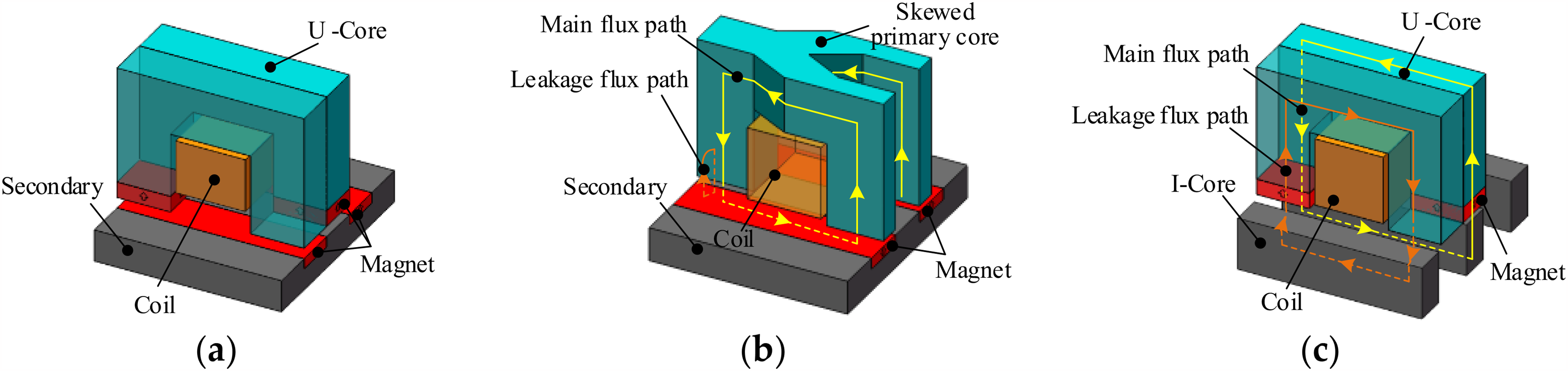
Fundamental structure of the proposed machine. (a) Basic model of the proposed machine. (b) Equivalent model without primary-PM. (c) Equivalent model without secondary-PM.
The operating principle of the proposed machine can be illustrated by two equivalent models, as shown in Figure 1. If the primary-PMs are left out, the flux paths produced by the secondary-PMs are shown in Figure 1(b). The operating principle of the equivalent model is similar to the claw pole transverse flux machine. According to the principle of minimum reluctance, the main flux goes into the U-core leg through the airgap vertically, then propagates into the other U-core leg, and crosses the airgap again into the secondary tooth, finally goes back to the secondary magnets. As it can be seen, the magnetic flux produced by the secondary-PM enwinds with the coil in counterclockwise direction. In addition, if the secondary-PMs are left out, the magnetic flux stimulated by the primary-PMs is shown in Figure 1(c). The operating principle is the same with transverse-flux flux-reversal machine. When the magnet is in alignment with the secondary core, the flux produced by this magnet will compete its loop through the U-core, airgap and I-core, forming the main flux path. The magnet above the secondary slot finish its loop also by the U-core and I-core with an opposite direction, but with a large airgap reluctance, forming the leakage flux path. The magnetic flux produced by the primary-PMs interlinks the coil also in counterclockwise direction. Hence, both the primary-PM and secondary-PM can produce useful flux linkage in the dual-PM TFLM. When the mover goes ahead continuously along the longitudinal direction, the flux linkage will vary with time, hence, the back electromotive force (EMF) will produce at the end of coil by the electromagnetic induction law.
Machine topologies
In order to achieve certain power level, the transverse flux linear machine can be expanded both along the longitudinal and transversal directions. Figure 2 shows this process. Figure 2(a) shows the fundamental structure of the dual-PM TFLM with concentrated coils enwinding each tooth. The two unit-models are juxtaposed in transversal direction to form a lateral four-toothed structure with equal tooth width as shown in Figure 2(b). Also, the two unit-models can be arranged with opposite direction, as depicted in Figure 2(c). In this case, the flux paths in the middle teeth are in the same direction, and the currents in the middle slot cancel out each other. Hence, the middle slot can be removed, forming a three-toothed structure with unequal tooth width as shown in Figure 2(d). Furthermore, three unit-models can achieve a four-toothed structure with two wide teeth and two narrow teeth as shown in Figure 2(e). For the sake of further utilizing the inner space under the slot, each primary tooth tip is designed as trapezoid shape as shown in Figure 2(f).
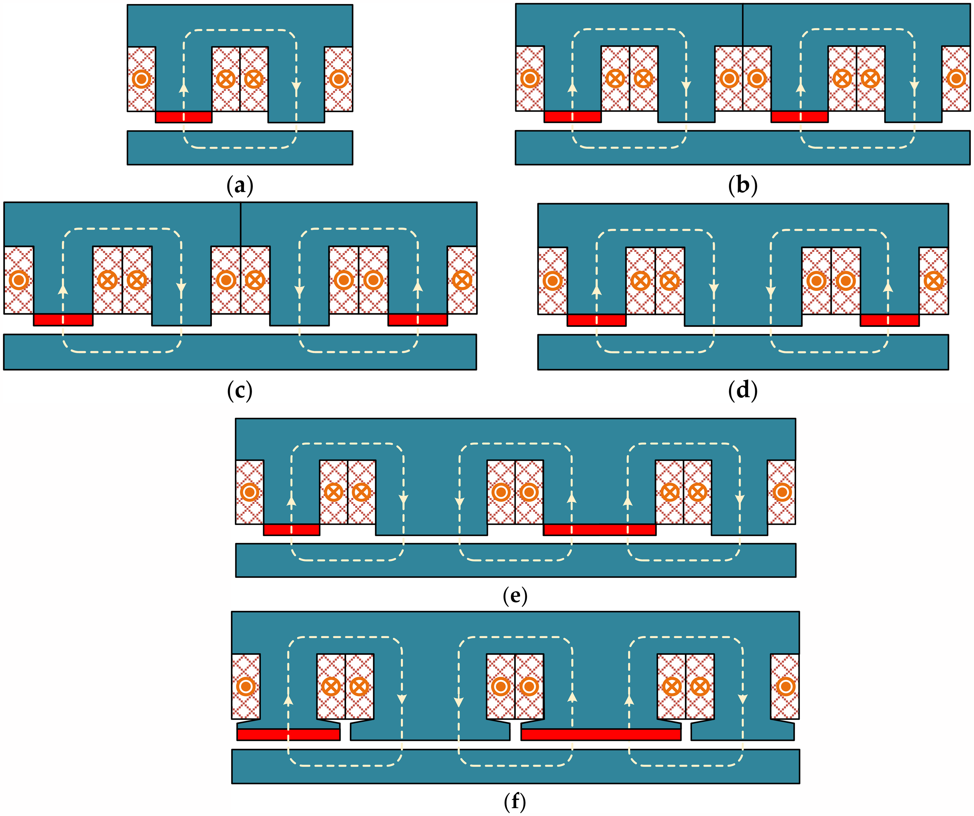
Machine topologies of the proposed machine. (a) Unit model. (b) Two unit-models in parallel with same direction. (c) Two unit-models in parallel with opposite direction. (d) Unequal tooth width structure by two unit-models. (e) Unequal tooth width structure by three unit-models. (f) Unequal tooth width structure with tooth shoe by three unit-models.
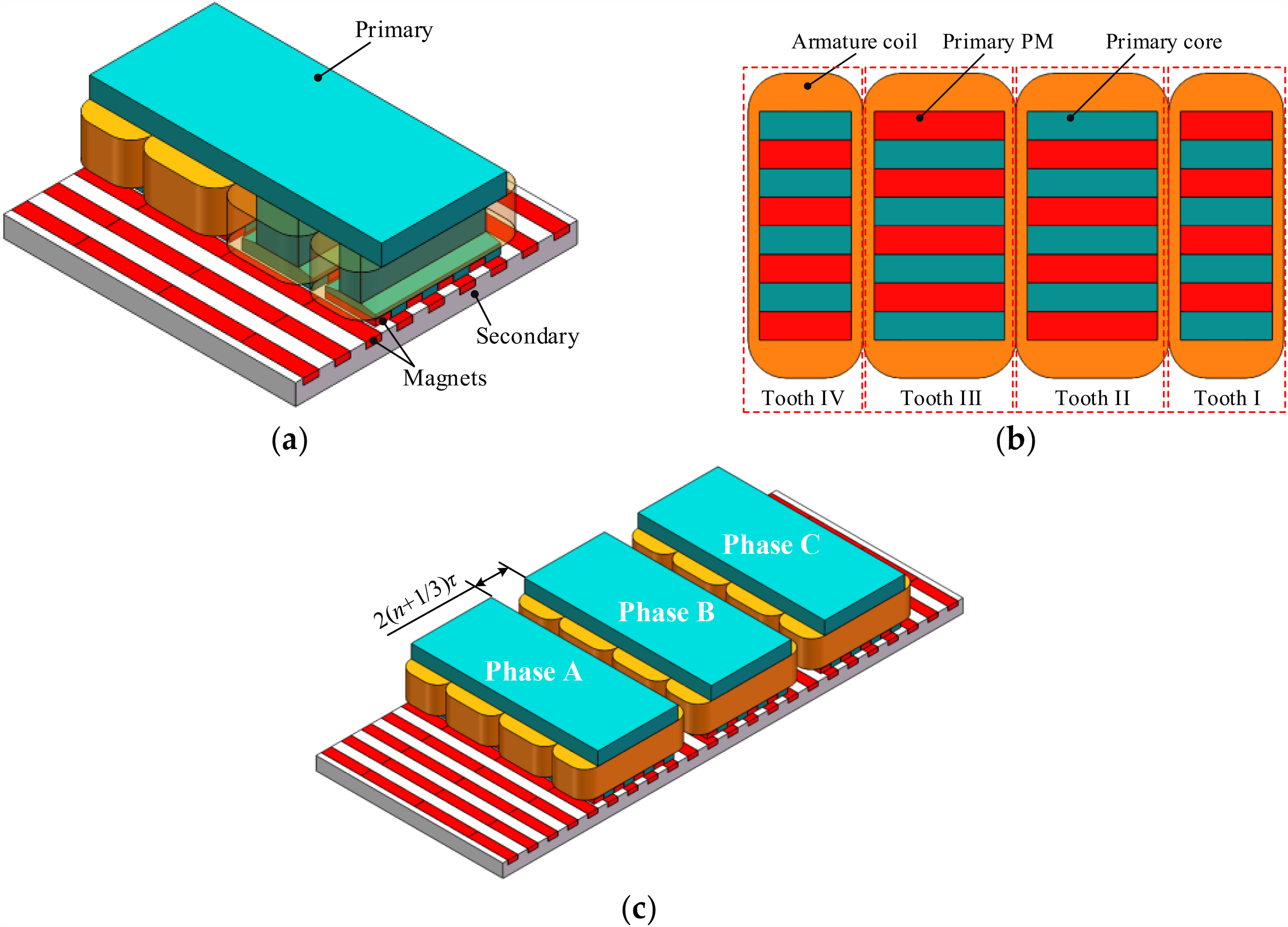
Based on the structure shown in Figure 2(f), a single-phase dual-PM TFLM can be obtained as shown in Figure 3(a). The detail of the primary magnets and winding arrangement is depicted in Figure 3(b). From right side to left side, the four primary teeth are named as Tooth I, Tooth II, Tooth III and Tooth IV successively. Obviously, Tooth I and Tooth IV have same tooth width while Tooth II and Tooth III is equal width. The magnets arrangement on Tooth I and Tooth III are in phase while it is a pole pitch delay for the Tooth II and Tooth IV. In order to gain the ability of self-startup and reduce the force ripple, the machine is designed as multiphase structure. Figure 3(c) shows the three-phase dual-PM TFLM. Three primary parts are arranged along the direction of motion with a phase shift of 120° electrical degree among each phase.
Fundamental structure of the proposed machine. (a) Basic model of the proposed machine. (b) Equivalent model without primary-PM. (c) Equivalent model without secondary-PM.
Fundamental electromagnetic performance
Thrust force expression
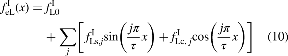
The single-phase dual-PM TFLM is constructed with a certain amount of fundamental machines. If the higher harmonic is omitted the flux linkage interlinking the armature can be expressed as
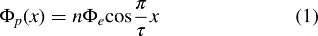
Wherein, Φ e indicates the permanent magnet flux linkage of a unit model, n is the total number of unit models of a single-phase structure, τ represents the pole pitch which is defined as the half distance between adjacent permanent magnet pieces along longitudinal direction.
With the motion of primary, the back electromotive force (EMF) will be produced at the open circuit condition, and there is
Wherein, N represents the number of coils, v represents the velocity of the mover,
When applied the sinusoidal current in phase with the back EMF, the thrust force generated by the single phase can be obtained by energy conversion law, as
Wherein, ip represents the instantaneous current of a phase winding, I represents the root mean square of the applied current.
As it can be seen, the single phase thrust force fluctuates twice over an electrical cycle. The amplitude of the fluctuation is the same with average thrust force, resulting in a large force ripple. For the three-phase configuration of the TFLM, the fluctuation of the second order harmonic will be eliminated and the resultant thrust force can be expressed as
Basic performance
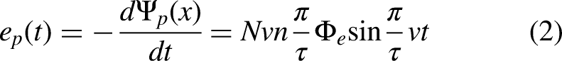
Since the phase winding of the dual-PM TFLM is independently arranged along the longitudinal direction and there is no common flux crossing the nearby primary cores, the magnetic coupling of the three primaries can be ignored. For the sake of reducing the simulation model, a single phase is established via commercial software JMAG Designer as shown in Figure 4(a). The three phase results can be obtained by shifting the initial position of the mover and adjusting the corresponding excitation currents. Namely, the mover will be shifted by 2τ/3 and 4τ/3, respectively, for phase B and phase C, while the applied current lead angle will be shifted by 120 and 240 degrees. The result of mesh is shown in Figure 4(b). The concerning areas, namely, the permanent magnet, air gap, are fine meshed and the total number of mesh elements is 773,979 with 194,202 nodes for the single-phase model.
Three-dimensional model of a single-phase dual-PM TFLM. (a) 3-D finite element model, (b) Mesh result of the model.
Figure 5 gives the three-phase flux linkage distribution at open circuit condition. As can be seen, the flux linkage is bipolar and sinusoidally distributed. Figure 6(a) shows the back EMF waveforms at the speed of 1 m/s. Figure 6(b) describes the harmonic distribution of the phase EMF. The amplitudes are 73 V, 7.6 V and 0.6 V for the fundamental, third, and fifth harmonic order, respectively. The phase back EMF is flat-top shape as the third harmonic is dominant. However, the third harmonic can be eliminated by star connection at the end of winding, and a highly sinusoidal line back EMF can be gained.
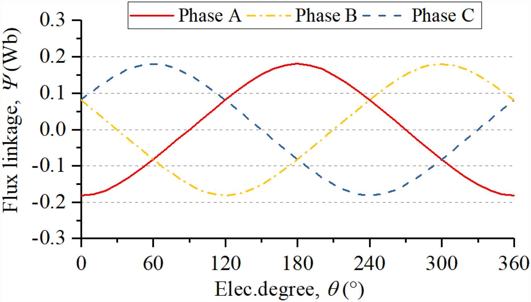
Flux linkage distribution of dual-PM TFLM.
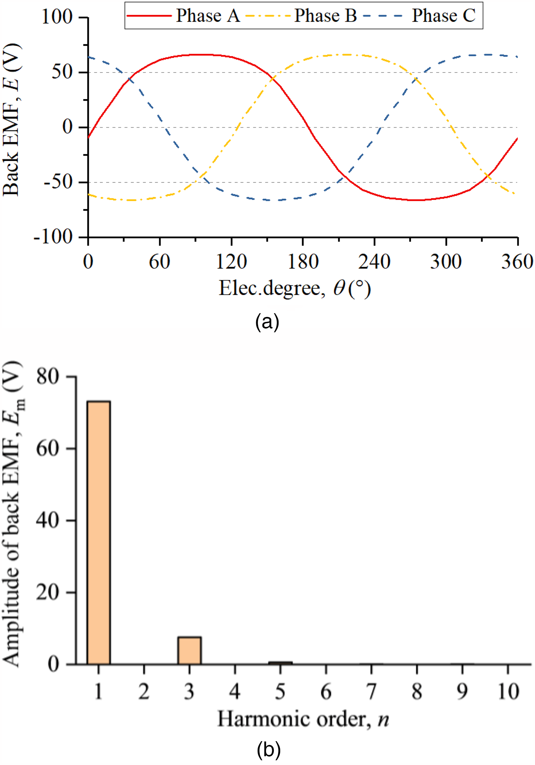
Phase back EMF distribution of dual-PM TFLM over an electrical cycle. (a) Waveforms distribution of three-phase EMF, (b) Harmonic distribution.
When the three-phase symmetrical currents are applied in each phase winding, the phase thrust force can be obtained. The total thrust force is the sum of each phase thrust force as depicted in Figure 7. As can be seen, the single phase thrust force has high ripple component as predicted by (3). The average thrust force is 842N under the rated current density of 5 A/m2. The peak-to-peak force ripple is 53.6N which gives a force ripple of 6.4%.
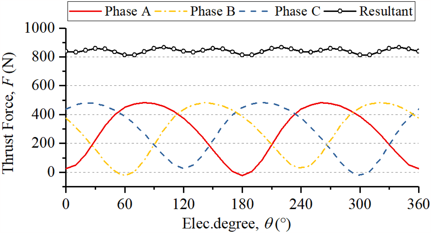
Single phase and resultant three-phase thrust force distribution of dual-PM TFLM.
The force ripple will deteriorate the performance of linear machine. Since the load contacts the mover of the linear machine, the force ripple will be reflected directly on the load, resulting in velocity fluctuation, and low position accuracy especially at low speed. In order to further investigate the force ripple, the following pages will focus on the reasons referring to the force ripple and estimate possible approaches to suppress the force ripple.
Detent force
The detent force is produced by the interaction of permanent magnet and magnetic core, which manifests itself by the phenomenon that the motor tends to be balanced at several particular points over an electrical cycle. According to the mechanism of production, the detent force of a linear machine can be further divided as cogging force and end force.
Cogging force
The cogging force is produced under the coupling area between the primary side and the secondary side, which is also existed in corresponding rotary machine type. Figure 8 shows two balance position on a primary tooth of the proposed machine. When the primary magnets are in alignment with secondary magnets, any attempt to move the primary away will suffer an additional force to pull it back. However, if the magnets are in alignment with iron core as shown in Figure 8(b), a little disturbance will make the primary further go away from the balanced position. Figure 9 depicts the sketch of cogging force variation. The stable balance point shown in Figure 8(a) refers to the position at x = τ while the unstable balance point shown in Figure 8(b) corresponds to the position at x = 0 and x = 2τ.
Balance position of the dual-PM TFLM on a cross section of primary tooth. (a) Stable balance point. (b) Unstable balance point.
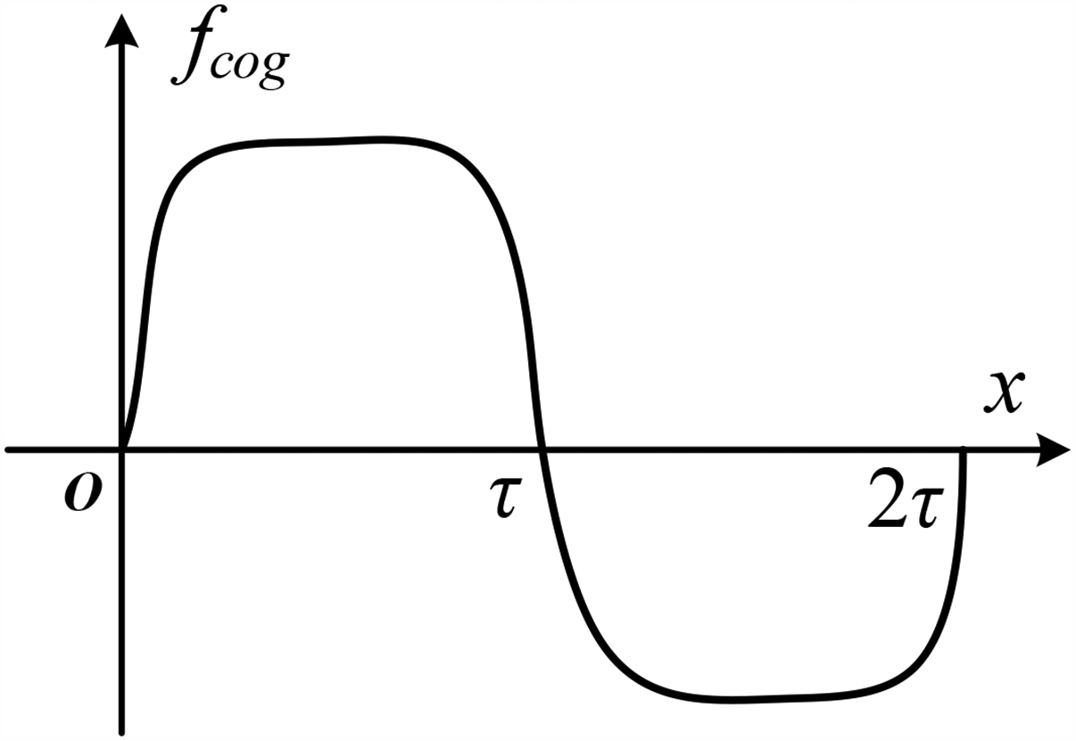
Sketch of cogging force distribution of a single primary tooth in dual-PM TFLM.
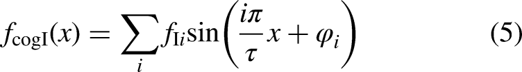
The cogging force on a primary tooth has a period of 2τ. Therefore, the cogging force on Tooth I can be expressed as Fourier series, and there is
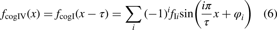
Tooth IV has the same dimensions with Tooth I but shifted by a pole pitch, hence, the cogging force on Tooth IV can be deduced as
Tooth III is in phase with Tooth I but the width is different. There is

Tooth II has the same dimensions with Tooth III but shifted by a pole pitch. Similarly, the cogging force on Tooth II can be expressed as

The total cogging force of a single-phase TFLM is the sum of the four individual tooth, which can be deduced as
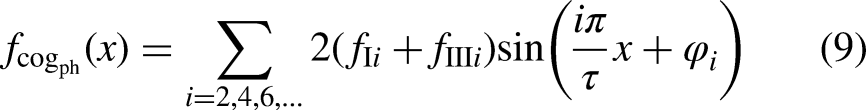
As it can be seen, the total cogging force of the proposed linear machine has a period of τ, and the fundamental and other odd harmonics of the cogging force is cancelled out inherently.
End force
The finite length of the primary in dual-PM TFLM makes an additional detent force, which is mainly occurred on the edge of the primary as shown in Figure 10. As the secondary side has a period of 2τ, the variation of end force on the edge has a period of 2τ. Without loss of generality, the detent force distribution on Tooth I and Tooth IV are shown in Figure 10.
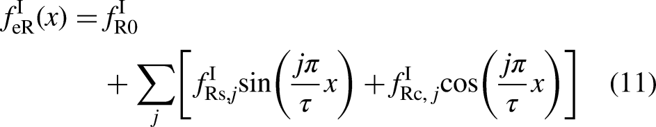
End force distribution on each primary tooth edge. (a) End force distribution of Tooth I and Tooth III; (b) End force distribution of Tooth II and Tooth IV.
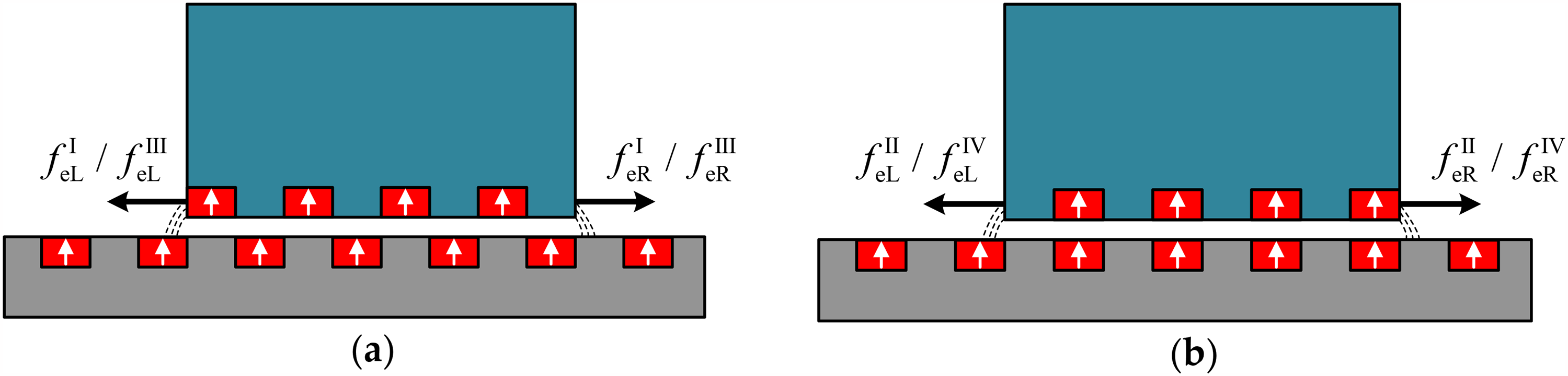
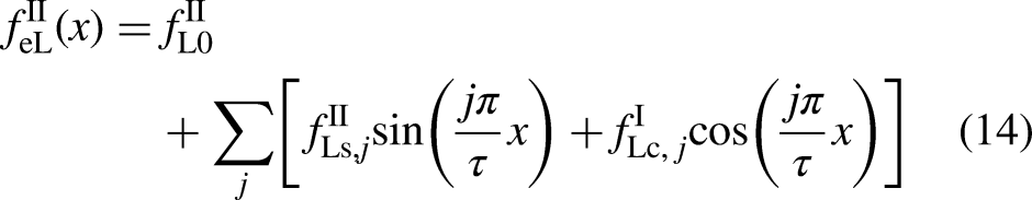
There is a magnet on the left side of Tooth I while it is a core on the right side. Hence, there is no direction connection of the end force variation. However, if we took a look at the Tooth IV, the end force distributions are similar compared to Tooth I. There exists a magnet on the right side while it is a core on the left side on the Tooth IV. If the left side position is marked as x and the right side position is marked as y, then there is a connection with the displacement of the primary, which is
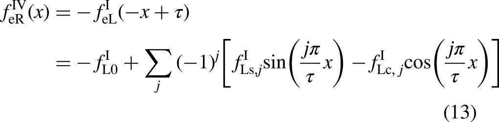
Similarly, we can get the end force distribution on Tooth II and Tooth III, which is
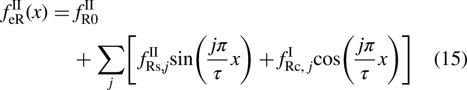
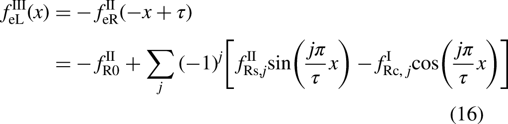
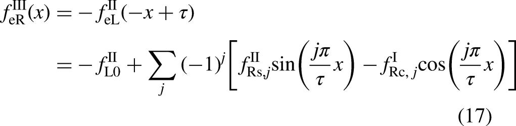
The total end force of a single-phase is the sum of end force on each tooth, and there is
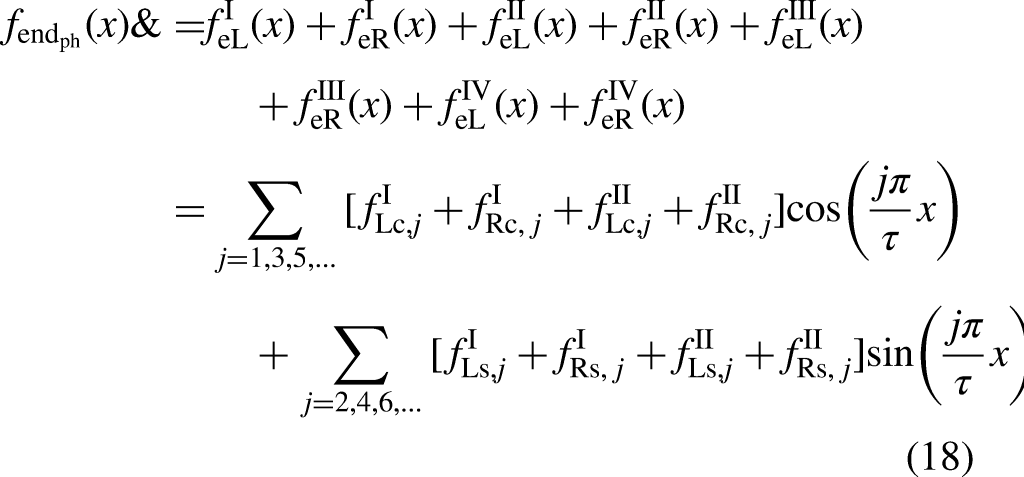
As it can be seen, the lowest order of the end force is 2τ, and the odd-order has a phase angle of 90° electrical degree different from the even-order harmonics, which is particular for the proposed machine from other linear machines.
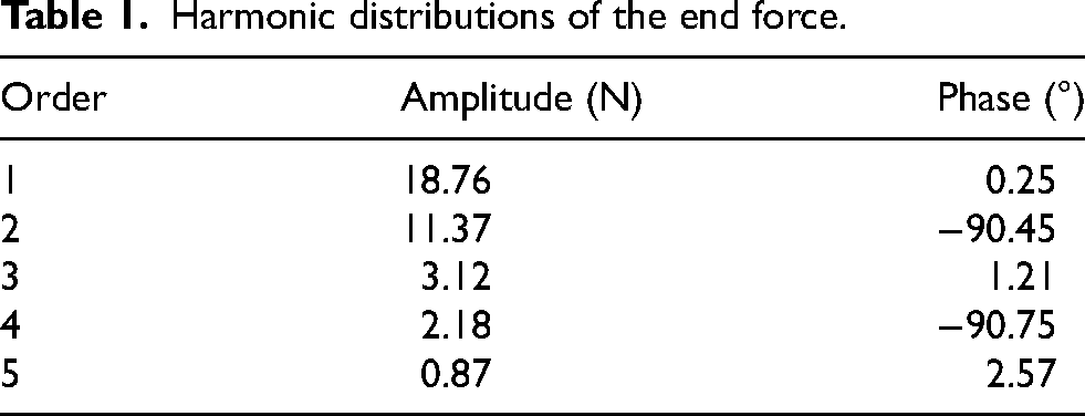
The detent force is calculated by 3-D FEM based on the single-phase model. Generally, it is hard to separate the cogging force and end force from each other since they are coupled together. In order to further estimate the detent force characteristic, an equivalent 3-D model without end effect is established and evaluated by FEM to obtain the cogging force alone. Then, the end force is obtained by the subtraction from the detent force. Figure 11 gives the waveforms of the cogging force, end force and resultant detent force of a single-phase model over an electrical period. The cogging force has a period of one pole pitch as indicated in (9). The peak value of the cogging force is about 8.5N. The end force is irregularly distributed and has a period of 2τ with a peak value of 28.1N. As can be seen, the end force is nearly zero at the region of [220, 320] electrical degrees where the two edges of the mover are above the secondary cores. The harmonic distribution of both amplitude and phase are list in Table 1 by fast Fourier transform (FFT). The results show that the odd orders and even orders have a phase shit of 90 electrical degrees just as indicated in (18).
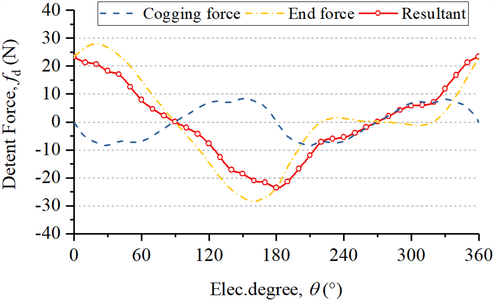
Separation of cogging force and end force of a single-phase dual-PM TFLM.
Harmonic distributions of the end force.
Three-phase detent force
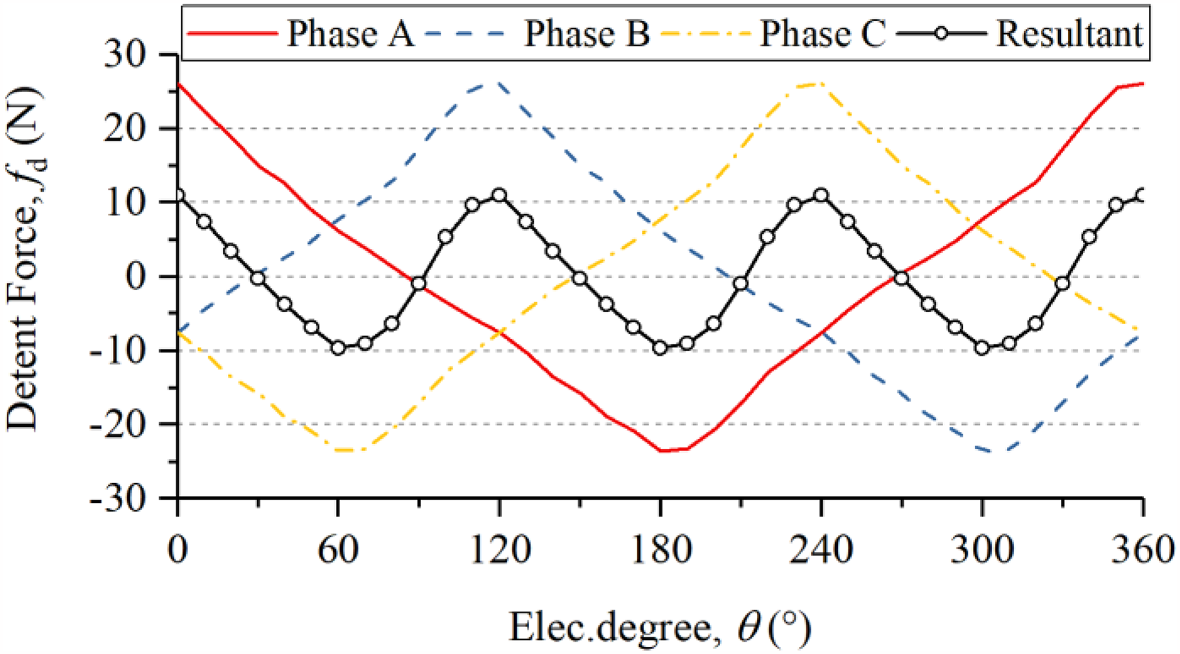
The resultant three-phase detent force is the sum of each single-phase detent force which can be expressed as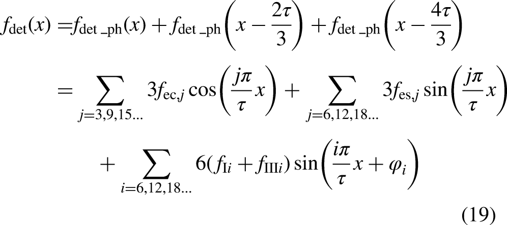
Figure 12 gives the detent force of each phase and the total three-phase. As can be seen, the three-phase detent force has a period of 2τ/3 and the peak force is 11N. By employing three-phase configuration, the detent force has been declined by over a half. As indicated by (19), the dominant component of detent force is the end force.
The single-phase and three-phase detent force distribution of the dual-PM TFLM.
Armature reactive field effect
When the three-phase currents are applied, the thrust force will generate. However, the iron core will go into saturation under the superposition of armature field and permanent magnet field. The saturated iron cores have impact on the inductance, and the phase inductance variation will produce reluctance force under the currents. Meanwhile, the flux linkage produced by the permanent magnets will be distorted when the iron core is saturated and additional force ripple will be stimulated by interaction between the higher order flux linkage and the currents.
Reluctance force
The phase inductance under different applied currents over an electrical cycle is shown in Figure 13.
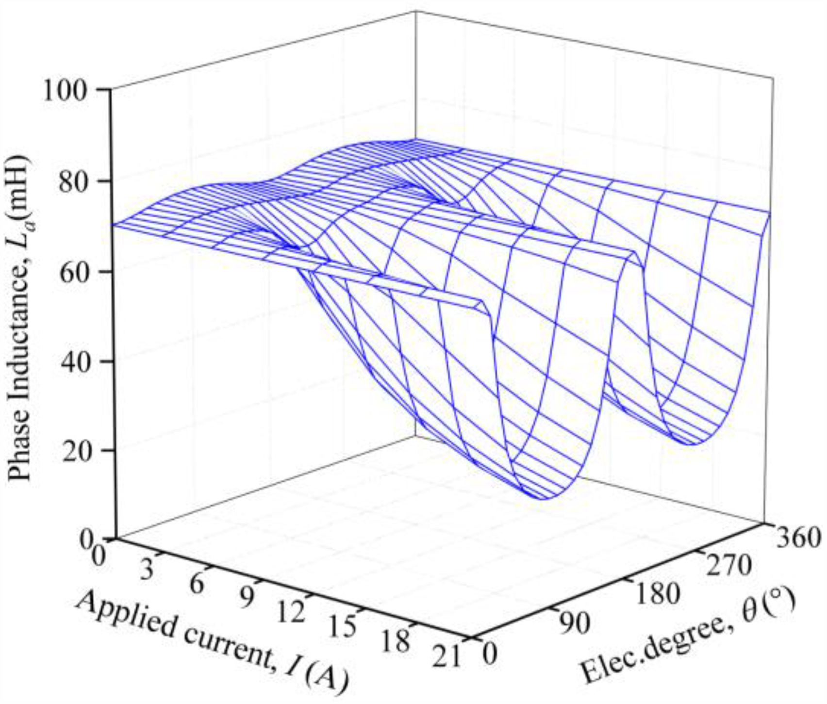
Single-phase inductance of the dual-PM TFLM variation under different applied currents over an electrical cycle.
As can be seen, when the applied current has low value, the phase inductance keeps nearly constant with the variation of mover position. However, when the applied current increases, the fluctuation in the phase inductance becomes higher. The lowest value of the phase inductance appears around the 90° and 270° electrical degrees where the applied phase current arrives at the peak value. The phase inductance is a function of both mover position and applied currents, which can be expressed as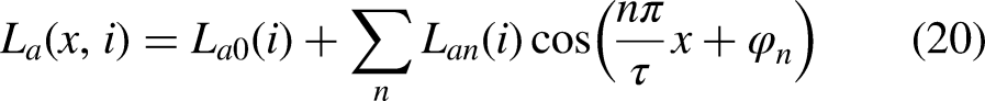
Where La0 and Lan represent the average value and n-th harmonic amplitude of the phase inductance, respectively. φn represents the initial phase angle of the n-th harmonic. The reluctance force can be calculated as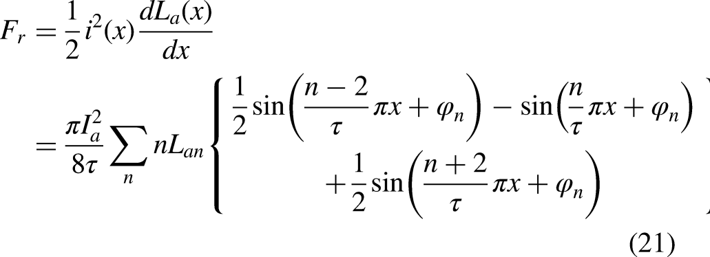
As indicated in (21), the n-th harmonic of the phase inductance will generate (n–2)-th, n-th, and (n + 2)-th force ripple when interacting with the fundamental phase current. Figure 14 shows the single-phase reluctance force produced by the rated current of 6 A as well as the resultant three-phase waveform. The results show that the single-phase reluctance force has a period of one pole pitch, and mainly presents to be a force ripple. The resultant three-phase reluctance force has a non-zero average force and the force ripple presents to be 6-th order harmonic. There exists a reluctance force in the total electromagnetic force, however, its magnitude can be neglected when compared to the thrust force.
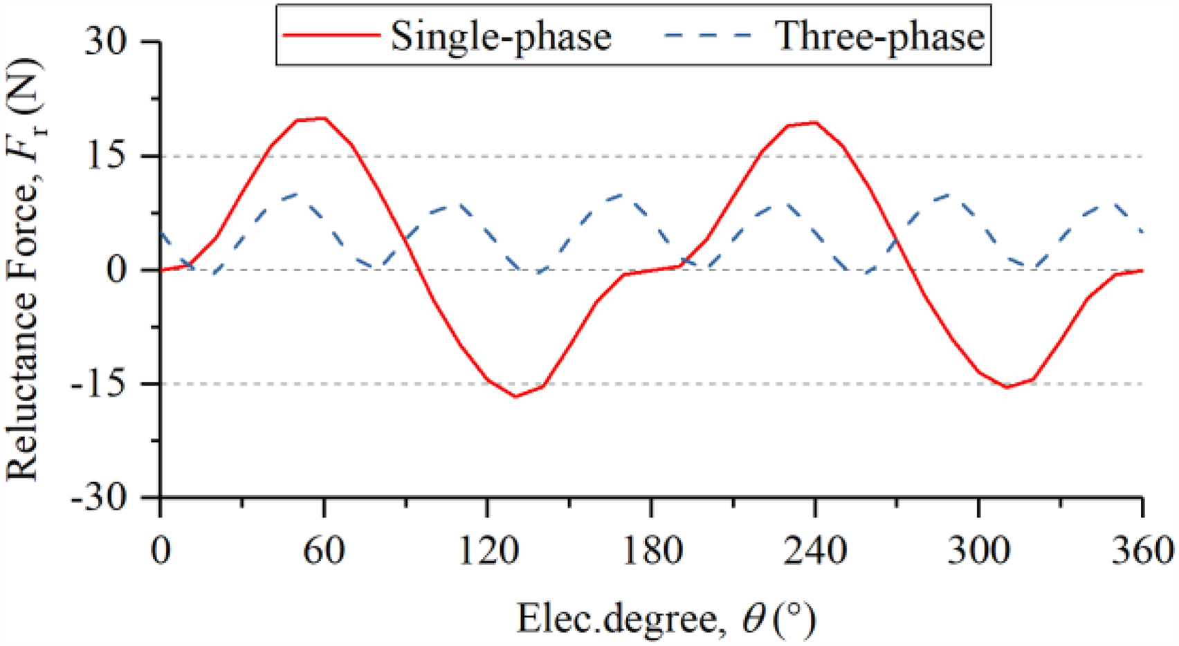
Single-phase and three-phase reluctance force distribution of the dual-PM TFLM under rated current over an electrical cycle.
Distortion of the on-load flux linkage
The iron saturation will affect the main magnetic path seen by the permanent magnets, resulting in distortion of the on-load flux linkage, which can also produce force ripple with interaction with fundamental currents. Figure 15 shows the flux linkage distribution when the armature current is existed or not. The results show that the flux linkage has been distorted when the armature current is applied. Figure 16 further gives the harmonics distribution of the permanent magnet flux linkage. As can be seen, the fundamental flux linkage at on-load condition is similar with that at no-load condition. But, the higher order flux linkage, especially of the 3-rd, 5-th, 7-th and 9-th orders, become bigger at on-load condition.
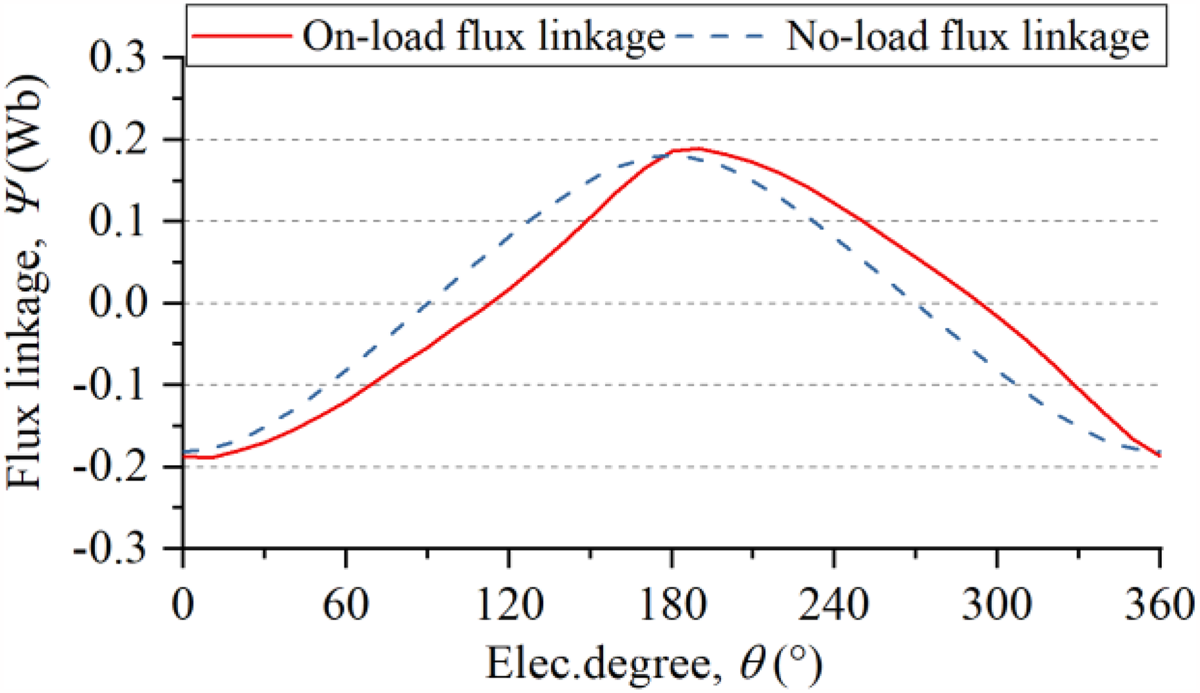
Single-phase flux linkage distribution at both on-load and no-load condition.
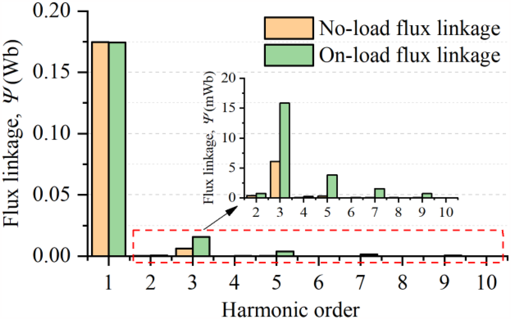
Harmonic distribution of single-phase flux linkage at both on-load and no-load condition.
The single-phase flux linkage has a period of 2τ, which can be expressed in Fourier series as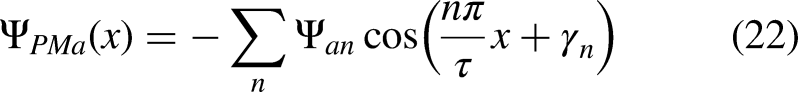
Where Ψan and γn represent the n-th amplitude and phase angle of the flux linkage, respectively.
If only the fundamental component of the current is considered, the interaction force between permanent magnets and armature currents can be deduced as
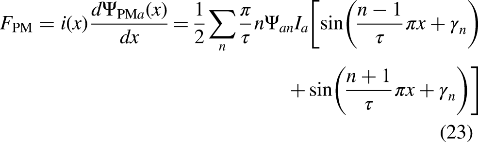
As indicated in (23), the n-th harmonic component of the flux linkage will generate (n–1)-th and (n + 1)-th force ripple when the armature currents are applied.
The detent force, reluctance force and harmonic force are the main reason for generating force ripple in the dual-PM TFLM. The force ripple can be eliminated by adopting multi-phase structure. Especially, for the three-phase configuration, only the 3-rd and integer multiple of 3 order harmonics can handle down to the resultant force ripple. Figure 17 gives the force ripple distribution under different armature currents. Generally, the force ripple fluctuates six times in an electrical cycle. The amplitudes of the force ripple increase as the applied current increases.
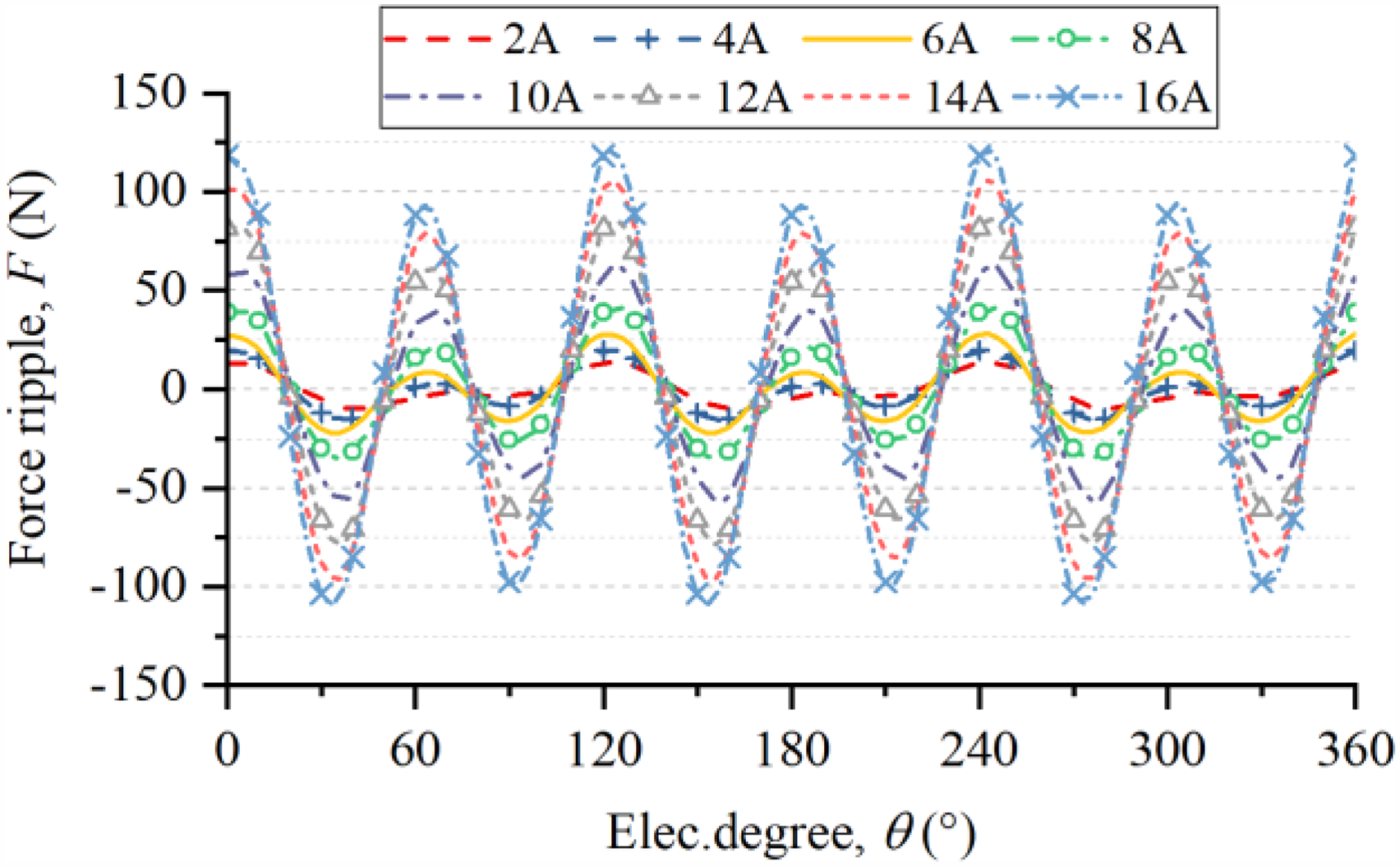
Comparison force ripple under different applied currents.
Suppression technologies
Linear motors are usually connected directly with the load and the thrust ripple are applied directly to the load. At low speeds, thrust ripple will result in unstable operating speeds and reduce the positioning accuracy. At high speeds, high frequency vibrations caused by thrust ripple make noise and material fatigue, which affects system life. Therefore, it is necessary to investigate the suppression method of thrust ripple to improve the motor output performance. The pole shifting and skewing methods of the secondary side of the proposed machine is estimated in the following paragraph. The thrust ripple is defined as the ratio between the peak-to-peak force and average thrust force, as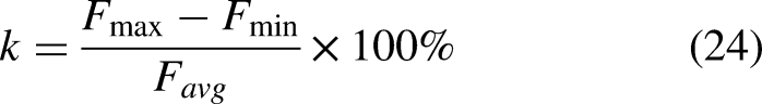
Pole shifting method
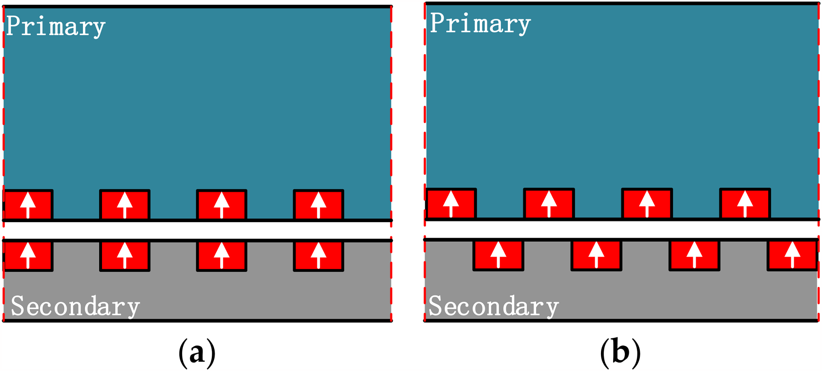
According to the structure of the dual-PM TFLM, two potential pole shifting methods are proposed as shown in Figure 18. Among them, the first scheme adopts two stages of pole shifting, and the motor secondary is divided into two sections along the transversal center line, and is shifted by Δx distance along the longitudinal direction. The second scheme uses a three-segment pole shifting in which the two sections at the ends are aligned in the longitudinal direction and the pole shifting distance is also set to Δx.
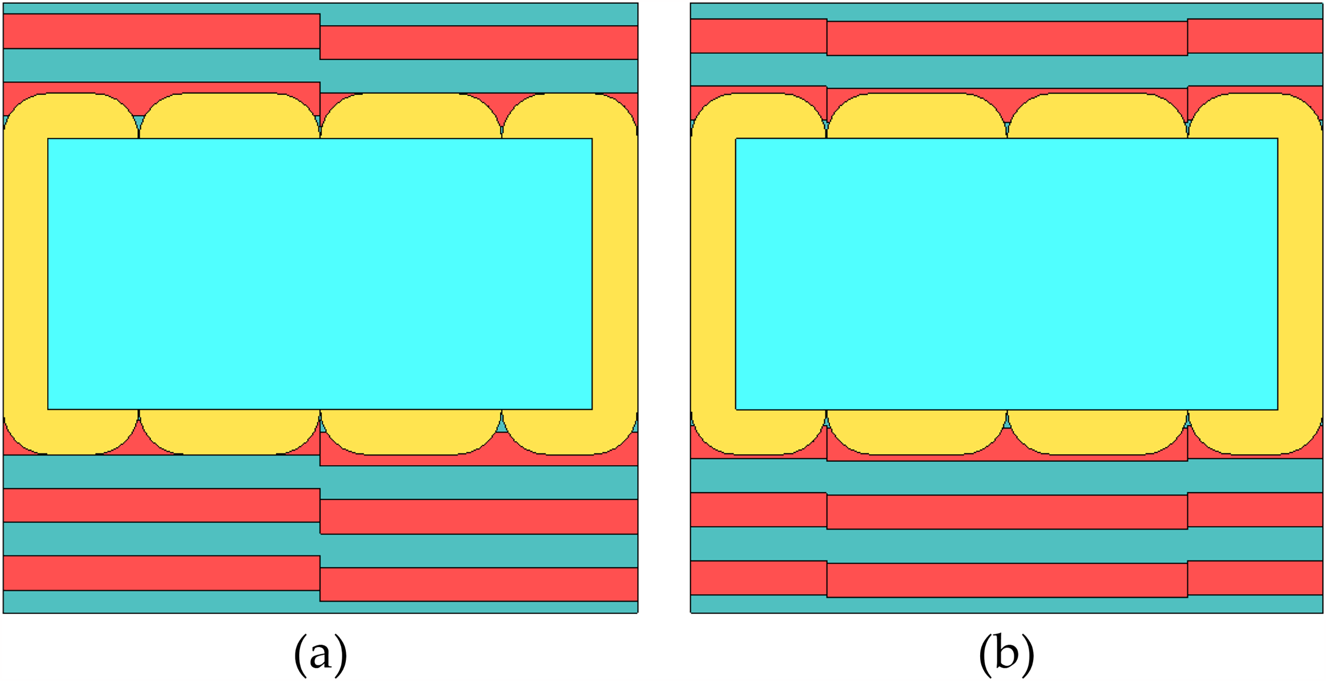
Pole shifting strategies applied to the dual-PM TFLM. (a) Two-section pole shifting method. (b) Three-section pole shifting method.
Figure 19 gives the single-phase thrust force distribution under different shifting distance. The results show that the shifting distance has a big influence on the waveform of single-phase thrust force. The amplitude decreases as the shifting distance increases. The two-section method has more distortion on waveform than the three-section method. Figure 20 gives the average thrust force and thrust ripple variation under different shifting distance. As can be seen, the average thrust force decreases with the increase of shifting distance. The two-section method cannot reduce the thrust ripple effectively. When the three-section pole shifting method is employed, the motor thrust fluctuation reaches a minimum value of 2.28% at the shifting distance of 2 mm. At this point, the average thrust of the output is reduced by 9.53%, but the thrust ripple is reduced by 54.49%.
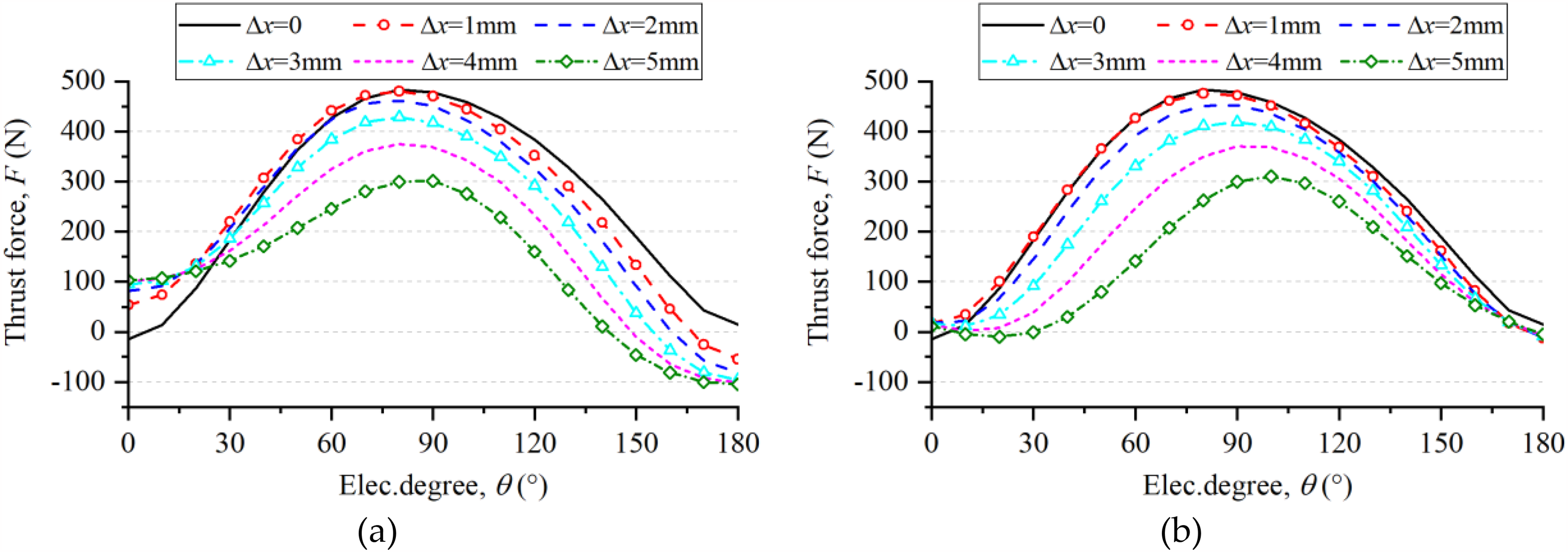
Single-phase thrust force distribution under different shifting distance of the dual-PM TFLM. (a) Two-section pole shifting method. (b) Three-section pole shifting method.
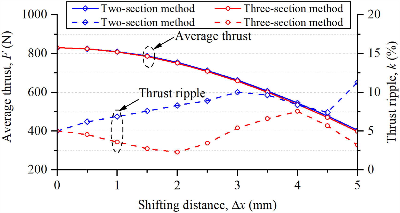
Comparison of different pole shifting methods on thrust ripple suspension.
Skewing method
In addition, the skewing method is also estimated in this paper. There are two skewing method for the dual-PM TFLM, as depicted in Figure 21. The V-shape skewing method breaks the secondary part along the transversal centerline, and each side is skewed by Δx both of the secondary cores and secondary magnets. The W-shape skewing method takes the centerlines of each primary slots, and divides the secondary part into four parts. The secondary cores and magnets of each part are further skewed by Δx.
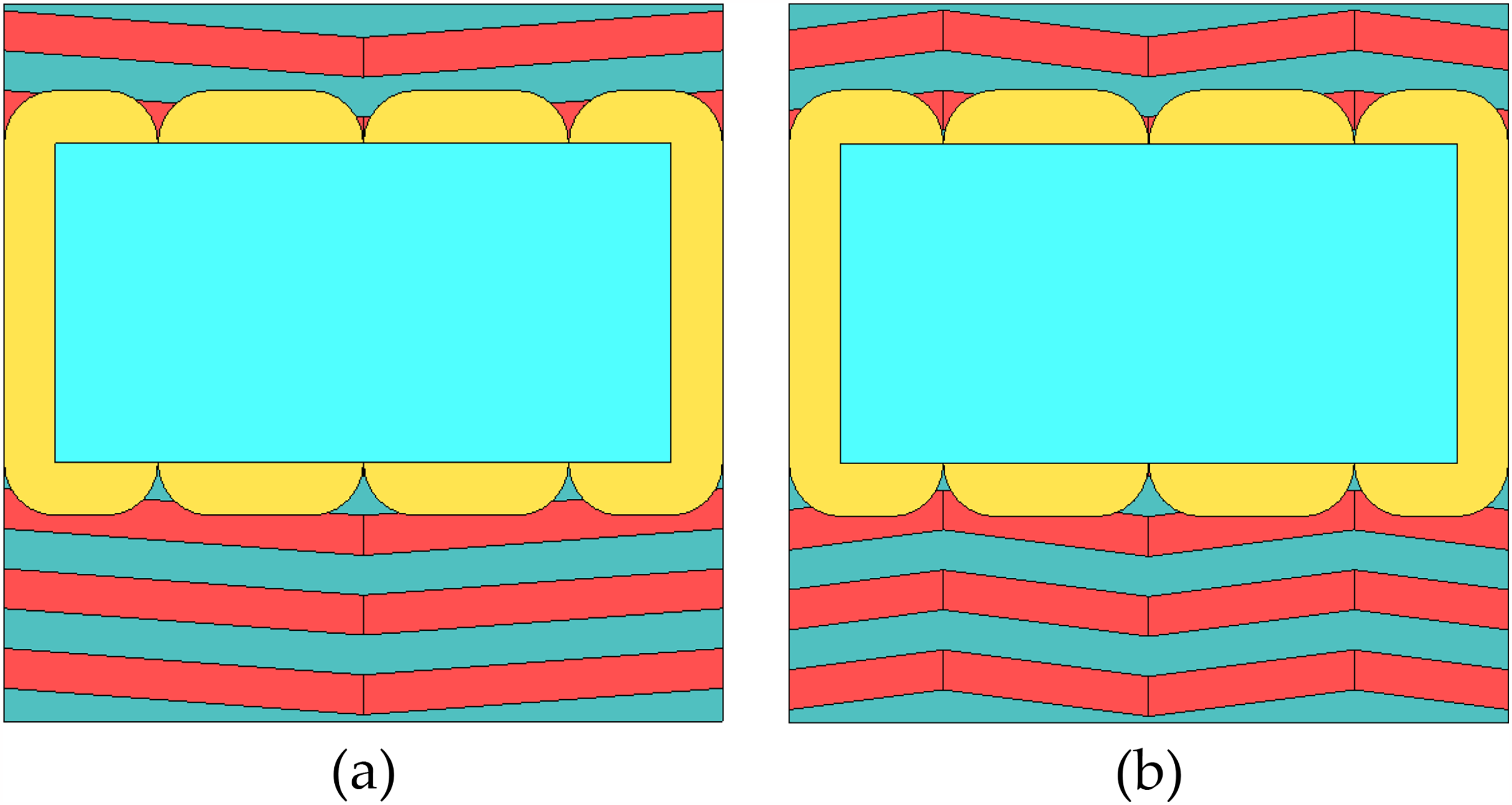
Skewing strategies applied to the dual-PM TFLM. (a) V-shape skewing method. (b) W-shape skewing method.
The single-phase thrust forces are investigated with different skewing distance as shown in Figure 22. The skewing distance has impact on the single-phase thrust force waveform distributions. The amplitude of the single-phase thrust force decreases as the skewing distance increases. But the distortion of the waveforms is less than the pole shifting method. It can be seen from the Figure 23 that under different skewing schemes, the thrust ripple of the motor shows a decreasing trend with the increase of skewing distance. When the skewing distance is less than 4 mm, the thrust ripple of V-shaped method is smaller than the W-shaped skewing method. When the skewing distance is greater than 4 mm, the thrust ripple in the V-shaped skewing method increases with the increase of the skewing distance, while the thrust ripple in W-shaped skewing method can be further reduced. The skewing of secondary part also reduces the permanent magnet flux linkage interlinking with the winding, which means that the average thrust of the motor decreases as the skewing distance increases. When the skewing distance is less than 2 mm, the two skewing methods have almost the same effect on the average thrust force, but the V-shaped skewing method can obtain smaller thrust ripple. When the skewing distance is greater than 2 mm, the average thrust force in the W-shaped skewing method is greater than the V-shaped skewing method. When the skewing distance is 4 mm, the V-shaped skewing method achieves a minimum thrust ripple of 1.31%, while the average thrust force is reduced by 11.6%, and the thrust ripple is reduced by 73.85%. Under the same skewing distance, the thrust ripple of the W-shaped skewing method is 1.12%, and the thrust ripple is reduced by 77.64%, and the average thrust is reduced by 9.73%. When the skewing distance is 4.5 mm, the W-shaped skewing method achieves the minimum thrust fluctuation of 0.71%, the thrust ripple is reduced by 85.83% while the average thrust is reduced by 12.02%.
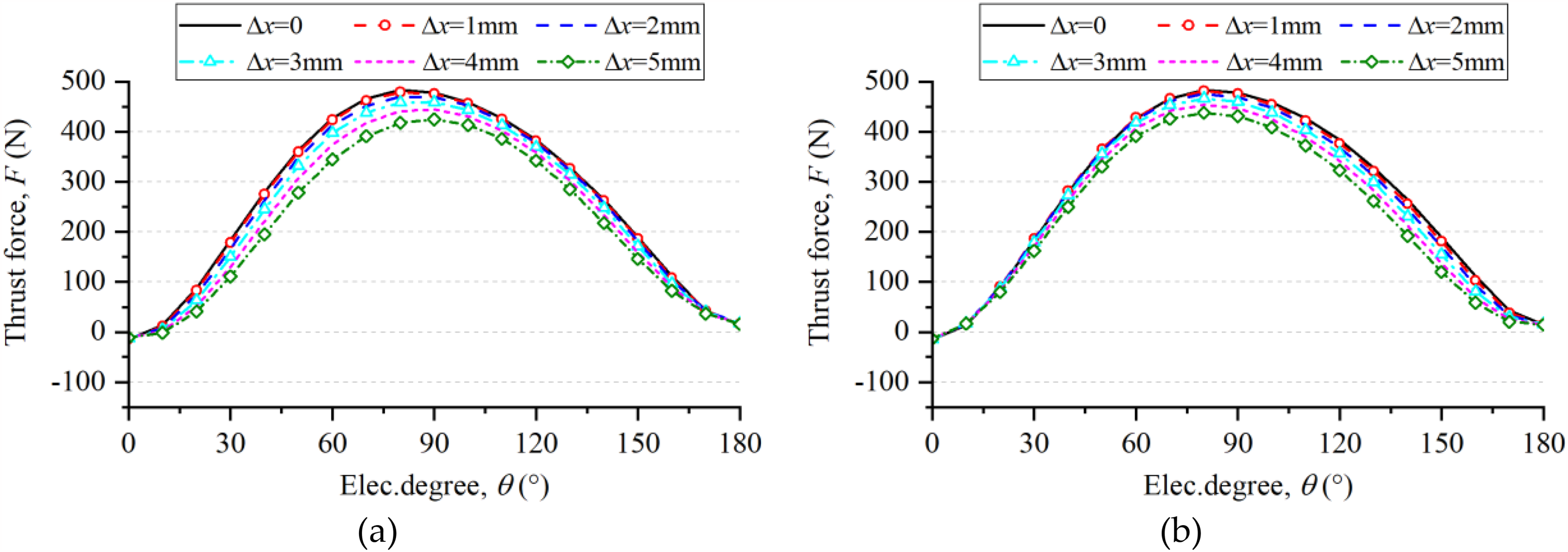
Single-phase thrust force distribution under different skewing distance of the dual-PM TFLM. (a) V-shape skewing method. (b) W-shape skewing method.
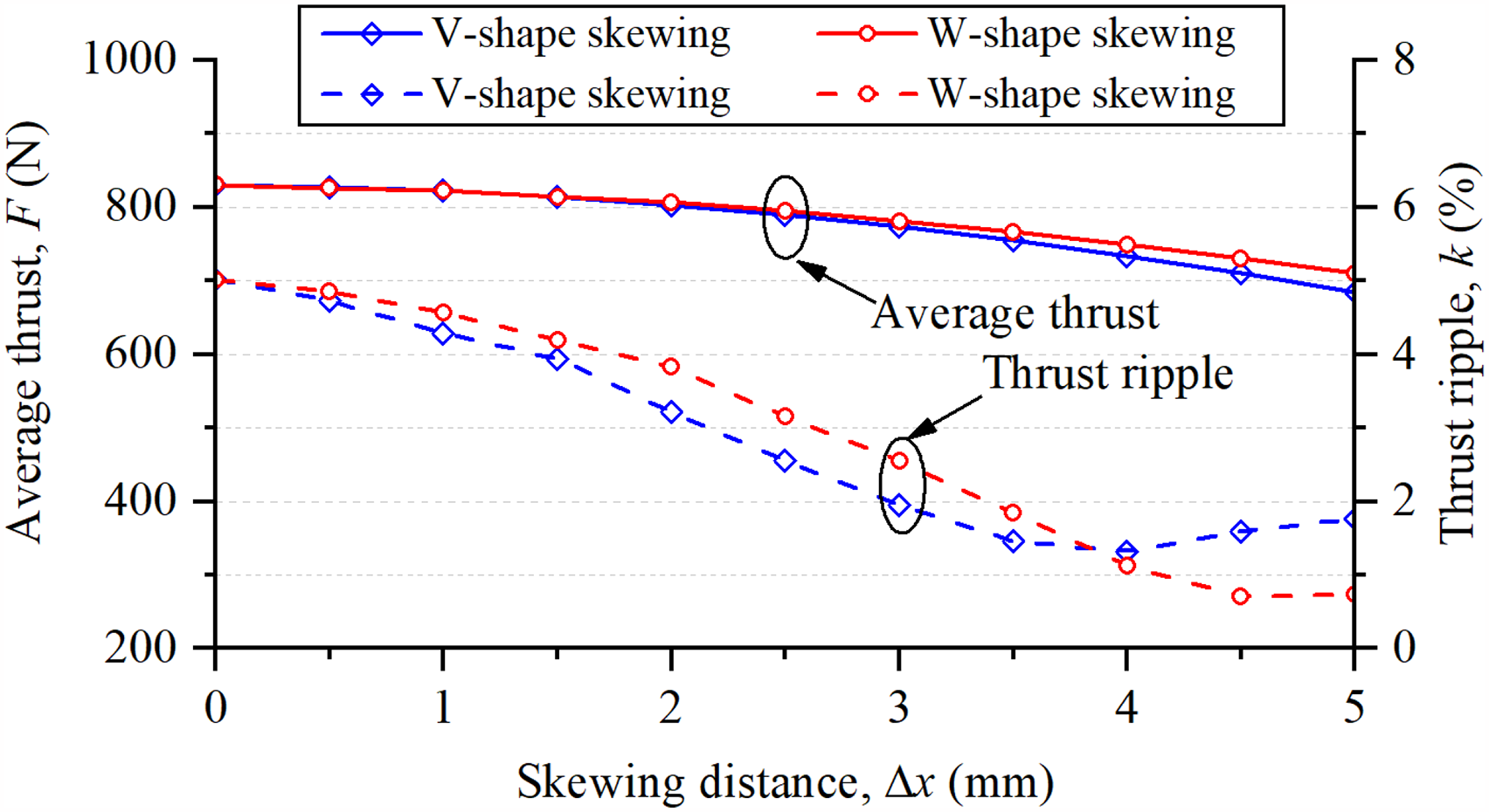
Comparison of different skewing methods on thrust ripple suspension.
Both the skewing method and three-section pole shifting method can reduce the thrust ripple of the dual-PM TFLM, but all the suppression methods make the manufacturing complex. The pole shifting method seems to be more feasible as the permanent magnets are rectangular. However, the skewing method is more effective to suppress the thrust ripple but the skewing secondary cores and magnets increase the manufacturing cost.
Conclusions
A dual-PM transverse flux linear machine has been investigated in this paper. The method for extending the fundamental structure to achieve high thrust force has been explained, which is also suitable for other topologies of transverse flux machines. The thrust ripple is emphasized and the inducements for the thrust ripple is analyzed, including the detent force, reluctance force and distortion of flux linkage. The dual-PM TFLM operates in close to the saturated region, hence, the iron saturation has an important impact on the output thrust performance since the thrust ripple increases as the applied currents increase. The thrust force shows to be a function both of the applied currents and the relative position between the primary mover and the secondary stator. Moreover, the pole shifting method and secondary skewing method are estimated to suppress the thrust ripple in the dual-PM TFLM. The results show that the W-shaped skewing method can reduce the thrust ripple most effectively at the expense of complex manufacturing craft.
Footnotes
Acknowledgment
This work was supported by Fundamental Research Funds for the Central Universities under Grant QJ2023-009.
Funding
The authors received no financial support for the research, authorship, and/or publication of this article.
Declaration of conflicting interests
The authors declared no potential conflicts of interest with respect to the research, authorship, and/or publication of this article.