
Abstract
In order to further improve motor output torque, a harmonic-oriented design and analysis method is proposed for a dual-airgap flux modulated permanent magnet (FMPM) motor. In this paper, based on flux modulation theory, airgap flux harmonics are investigated, and the torque generation mechanism under different operation modes is analyzed in detail. Also, the leading airgap flux harmonics have a significant influence on the motor output torque. Then, numerical optimization methods are employed to specifically optimize key design parameters such as the tooth widths of inner and outer rotors, aiming to increase leading airgap flux harmonics under different operation modes. The results indicate that the motor performance following optimization demonstrates a significant enhancement in the effect of specific working harmonics, thereby improving the torque characteristics of the motor. The prototype was fabricated and tested, verifying the feasibility of the proposed DSFMPM motor and the effectiveness of the harmonic-oriented optimization design. This research not only elucidates the relationship between the mechanism of torque generation, airgap harmonics, and motor design parameters but also provides a new perspective and methodology for the design of efficient and high-performance dual-stator motors.
Introduction
Permanent magnet motors have been widely applied in the field of electrical vehicles, due to the merits of high output torque and high efficiency. 1 With the development of modern transportation, the actual driving cycle often consists of many operation modes, including frequent start and stop, acceleration, deceleration, high-speed cruise, heavy load climbing, and so on. 2 It is noted that the aforementioned different operation modes pose increasingly demanding design requirements for driving motors. So, it has been a hot but challenging issue on how to realize the multi-mode high-performance operation of driving motors. 3
Recently, numerous researchers have dedicated efforts to investigating novel motor technologies aimed at enhancing performances across multi-operational conditions. Notable examples include the variable flux memory motor 4 and the hybrid-excited PM motor. 5 Due to their capacity for variable magnetic flux, these motors are capable of functioning in several modes. However, the application of these motors is constrained by challenges such as the complexity of their control systems and suboptimal motor efficiencies.
The Dual Stator Permanent Magnet (DSPM) motor not only exhibits flexible operating modes but also demonstrates advantages in delivering high torque density and power output, positioning it as a focal point of research in these application areas. 6 Researchers globally have conducted in-depth studies on dual-stator motors from various perspectives. In, 7 performance enhancements have been realized through the design and improvement of motor topological structures. In 8 and, 9 there has been targeted optimization of motor performance, especially in terms of torque capabilities, through the optimization of motor parameters. In addition, advanced control strategies have been applied to minimize torque ripple in dual-stator motors as indicated in. 10 However, due to the dual-airgap structure, the airgap flux harmonics become complex, which not only affects the torque output of the motor but also increases the torque ripple, which in turn affects the overall performance and stability of the motor. Therefore, it has become a key way to improve the performance of the motor by studying the airgap flux modulation mechanism of the DSPM motor and optimizing the motor design to control the airgap harmonics.
In recent years, airgap field modulation theory has been introduced and utilized to elucidate the working principles of various motors and to inform their design. 11 This theory has been further developed in the analysis and optimization of single-stator FMPM motors.12–14 However, the relatively pronounced magnetic coupling in the type of motors mentioned in these studies restricts their ability for multimodal operation. Additionally, these motors feature two electrical ports and two air gaps, leading to complex performance interrelations. Therefore, employing airgap field modulation technology to investigate torque performance enhancements in dual-stator motors under multiple modes presents a research topic worth exploring.
Addressing this issue, this study investigates a Dual-Stator Flux-Modulated Permanent Magnet (DSFMPM) motor to enhance torque performance across multiple modes. It introduces the concept of working harmonics, and based on airgap flux modulation theory, delves into the torque generation mechanism. Particular emphasis is placed on deciphering the working harmonics in the inner and outer airgaps and analyzing their relationship with key design parameters. Through the application of numerical optimization methods, key design parameters such as the tooth width of the stator and rotor are specifically optimized. By effectively controlling the leading working harmonics, a significant increase in torque output has been achieved across 3 modes, demonstrating a notable improvement in torque performance.
Motor topology configuration and airgap flux harmonics characteristics analysis
Motor topology configuration
This study introduces a uniquely structured DSFMPM motor, featuring both inner and outer stators and a dual airgap topology as illustrated in Figure 1. The rotor part, positioned in the middle, is devoid of PMs, thereby effectively mitigating the risk of demagnetization at excessively high temperatures. Additionally, the motor rotor employs a dual salient pole structure with varying numbers of rotor teeth on either side, ensuring compatibility with the different pole-slot combinations of the inner and outer stators. Both stators utilize concentrated armature windings, a design choice that shortens the length of the winding ends and consequently reduces the overall copper loss of the motor. The external stator is distinctively fitted with inverted “V”-shaped side magnets that are magnetized in opposite directions, creating a pronounced magnetic gathering effect in the middle tooth area. This configuration aims to enhance the power density and torque density of the motor. Moreover, a magnetic isolation ring designed to minimize magnetic field coupling is incorporated in the rotor. This design allows for the individual or collective operation of the inner and outer motors, achieving a highly flexible operational mode.
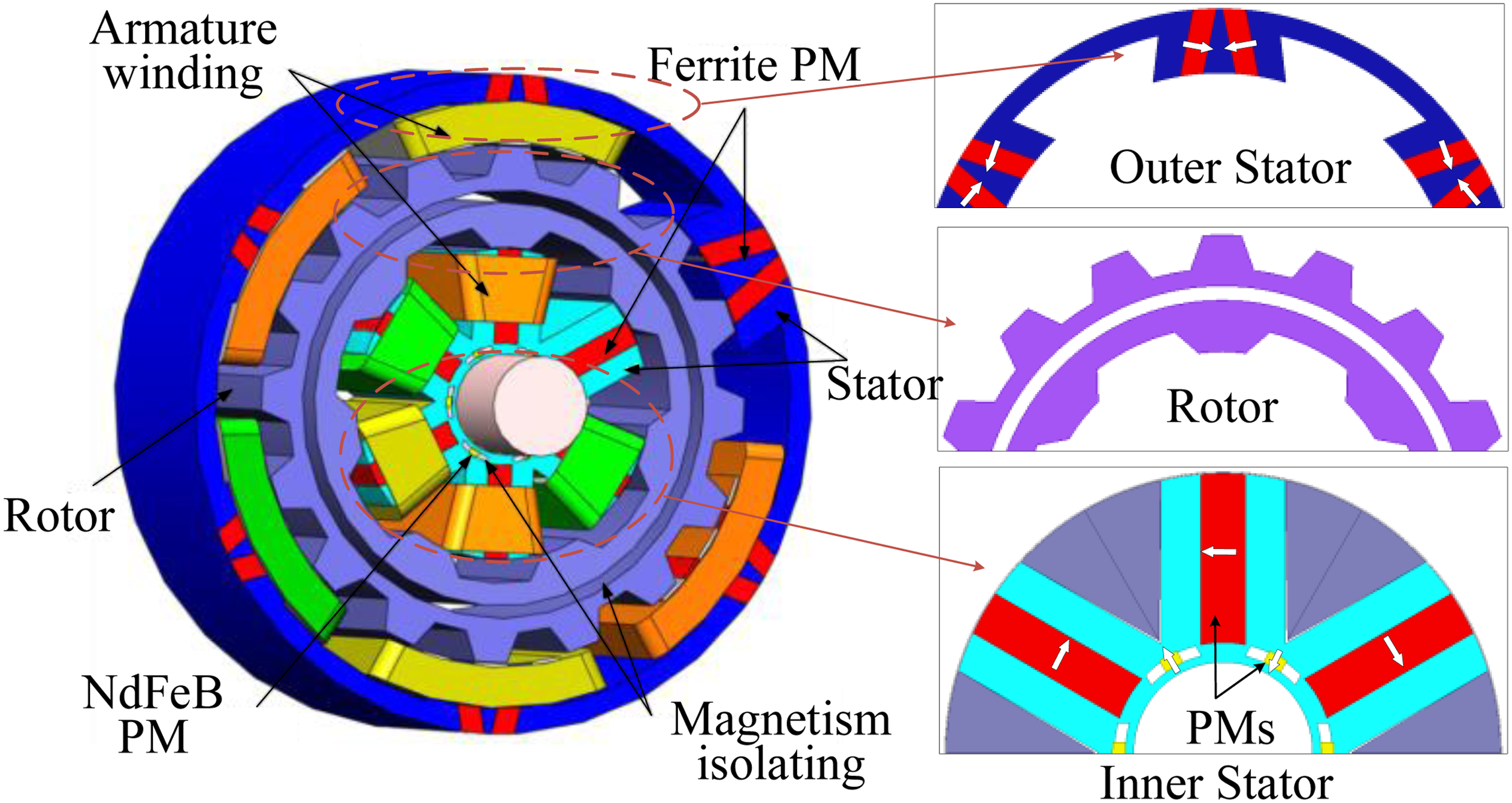
Topology of the proposed DSFMPM motor.
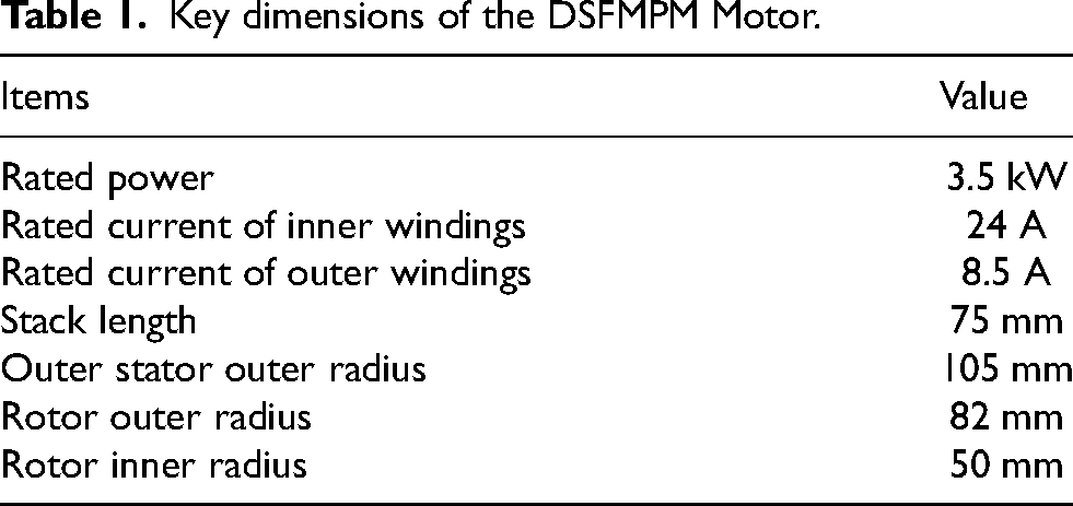
Based on the above structural features and actual operational requirements, the proposed motor can operate in three modes, whose correspondence with typical driving conditions is shown in Figure 2. In Mode 1, only the inner stator winding is energized, and the inner motor operates independently. Here, the electromagnetic torque is primarily generated by the inner air gap magnetic field. This mode is suitable for high-speed, light-load operation, such as cruising conditions. In Mode 2, only the outer stator winding is excited, and the outer motor operates independently. The torque is mainly produced by the outer air gap magnetic field. This mode is more suitable for acceleration or medium-load conditions. In Mode 3, both the inner and outer stator windings are simultaneously excited, enabling the inner and outer motors to operate cooperatively. The torque components generated by the two air gaps superimpose each other, providing stronger total output capability and superior dynamic response. This mode is suitable for low-speed, high-torque conditions, such as vehicle starting or climbing. At the same time, these different operating scenarios lead to differentiated design requirements. The performance demands of each mode directly guide the multi-objective optimization strategy proposed in the subsequent sections, aiming at comprehensive performance enhancement under various working conditions. The main performance characteristics and parameters of the motor are displayed in Table 1.
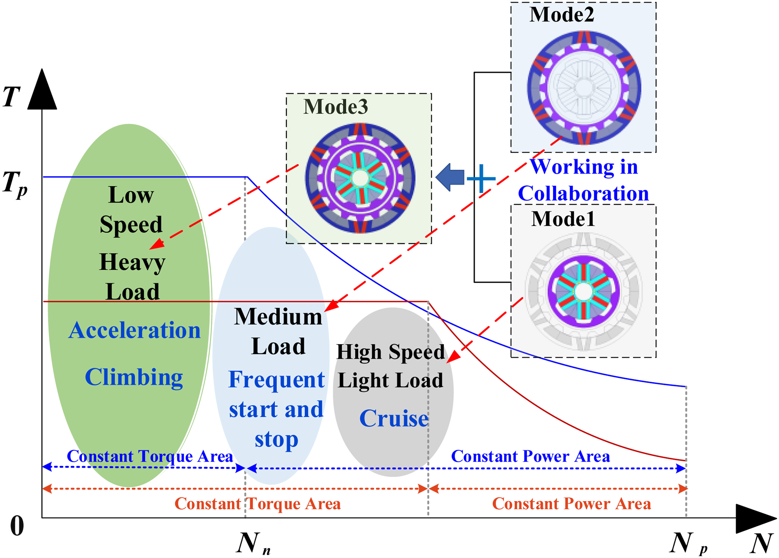
Working modes and motor performance requirements.
Key dimensions of the DSFMPM Motor.
Airgap flux torque harmonics analysis
Drawing from the theory of flux modulation, it is recognized that the original magnetomotive force (MMF) produced by the motor rotor can be viewed as a square wave. These square waves, modulated by the interaction of the stator and rotor teeth, induce a rich variation of magnetic flux density within the airgap.
15
The interaction between the motor's magnetic permeability and MMF generates a wealth of airgap harmonic components. These harmonic components significantly impact the motor's dynamic performance, including output torque and torque ripple. Subsequently, a detailed analysis of the torque characteristics of the DSFMPM motor is conducted utilizing the Maxwell stress tensor method.
16
The average torque and torque harmonics of the outer motor can be expressed as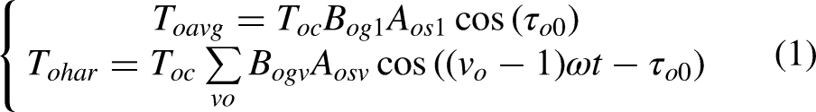
Correspondingly, the average torque, torque harmonic of the inner motor can be expressed as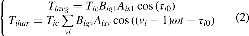
When the torque generated by the inner and outer airgaps is superposed, the average torque and torque harmonic of the motor can be expressed as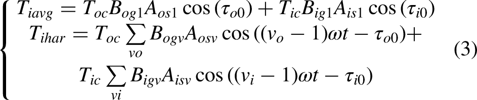
Upon analyzing the torque calculation relationship, it has been ascertained that the average torque of a motor predominantly depends on the distribution of magnetic flux density in the airgap. Moreover, only the interaction of radial and tangential harmonic components of the same order will have a substantial impact on torque production. It can thus be concluded that meticulous design of torque harmonics can not only enhance the output torque but also minimize torque ripple. Therefore, in practical application, the torque performance of a motor can be optimized by adjusting the coupling relationship between airgap harmonics and torque harmonics, providing a theoretical foundation for further performance enhancements in DSPM motors.
According to the airgap flux modulation theory, the airgap harmonics generated by permanent magnets form a series of spatial harmonics in the air gap through the modulation effect of rotor and stator teeth. To quantitatively analyze these harmonic components, this paper establishes a two-dimensional finite element analysis (FEA) model of the motor under no-load conditions, solves the steady-state magnetic field distribution, and extracts the radial airgap flux density Br(θ) along the midlines of the inner and outer air gaps over a complete mechanical cycle. These spatial waveforms are shown in Figures 3(a) and (b). To ensure sufficient harmonic resolution, the air gap is uniformly discretized into 1024 sampling points, and the sampled data is processed using Fast Fourier Transform (FFT) to obtain the harmonic components of the airgap flux density. The airgap flux density can be expressed as a Fourier series: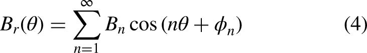
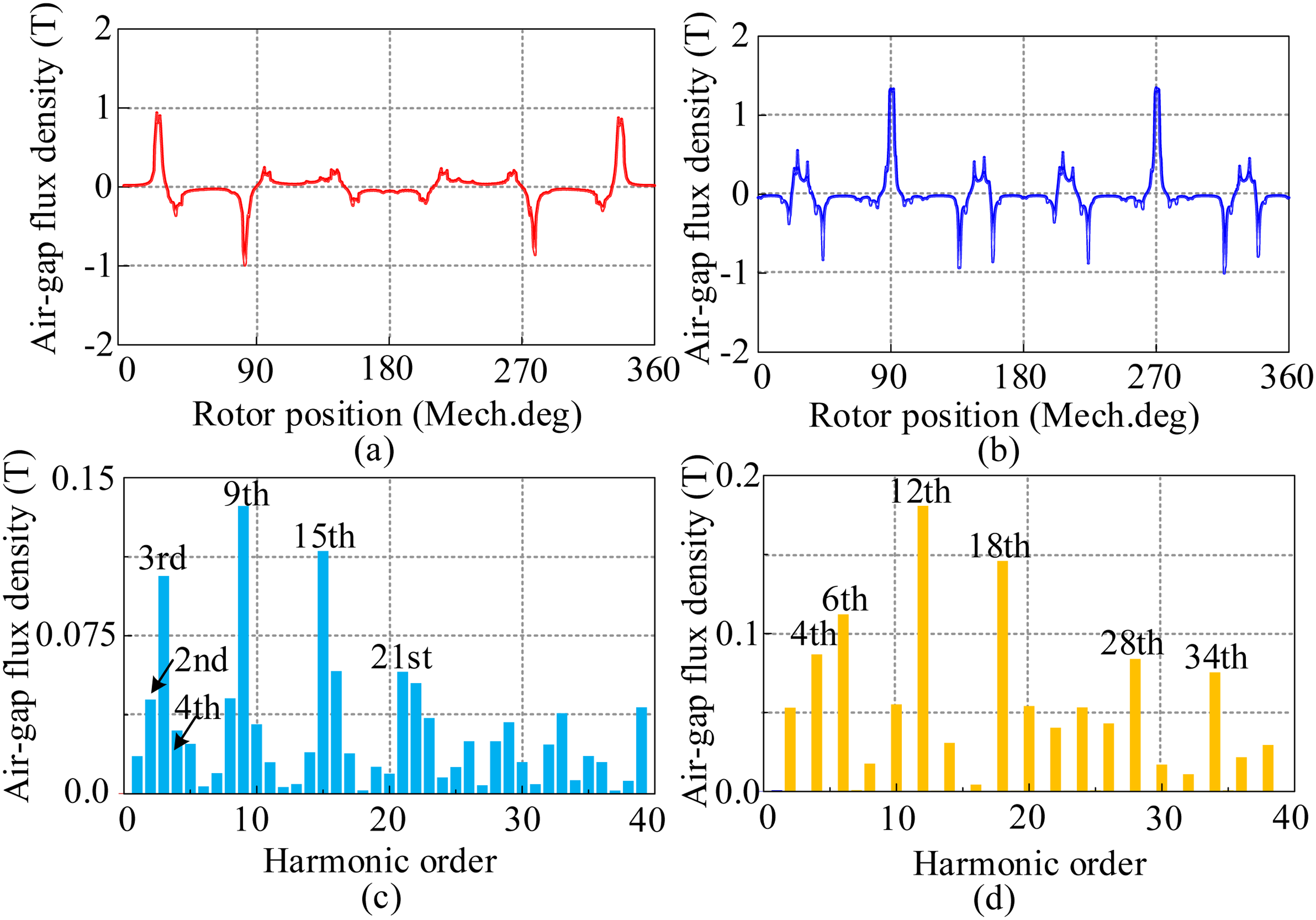
Analysis calculation of the inner and outer airgap flux densities. (a) Waveforms of the inner airgap. (b) Waveforms of the outer airgap. (c) Harmonic characteristics of the inner airgap. (d) Harmonic characteristics of the outer airgap.
Where Bn and Φn represent the amplitude and phase angle of the nth harmonic, respectively. Thus, the harmonic spectrum obtained from the FFT calculation displays the amplitudes of each harmonic, with the results plotted in Figures 3(c) and (d). The specific working harmonic order Pm,k can be represented as
17
: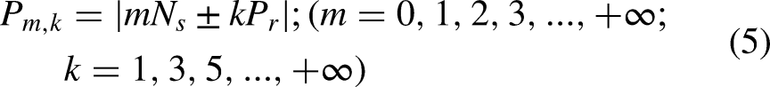
Where Ns is the number of flux modulating poles, Pr is the number of pole pairs of the PM, and the rotational speed of each airgap harmonic ωm,k can be represented as: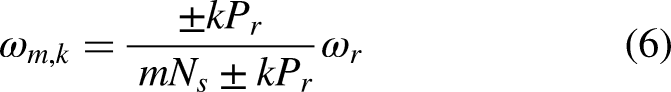
Where ωr is the rotational speed of the rotor, and the positive and negative values of the rotational speed of the airgap harmonics correspond to the same and opposite rotational direction as the rotor, respectively.
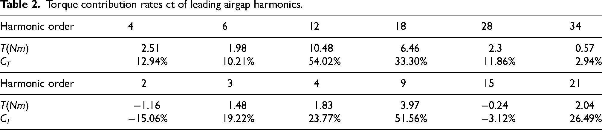
By comparing the harmonic orders obtained from FFT with the aforementioned modulation relationship, the dominant working harmonics that meet the modulation conditions and significantly contribute to torque are identified. These key working harmonics have been summarized in Table 2.
Torque contribution rates ct of leading airgap harmonics.
According to the above-described FFT procedure, the harmonic components presented in Figure 3 are quantitatively extracted from the FEA results, and their correspondence with the theoretical modulation orders confirms the validity of the harmonic analysis.
In this study, the proposed DSFMPM motor features an outer motor with 6 stator poles and 16 rotor poles, and an inner motor with 3 stator poles and 7 rotor poles. Based on equations (4) and (5), it is determined that in the outer motor, the harmonics of 4th, 6th, 12th, 18th, 28th, and 34th orders, and in the inner motor, the harmonics of 2nd, 3rd, 4th, 9th, 15th, and 21st orders are identified as the main contributors to the motor's output torque. These key working harmonics have been indicated in Figure 3(c) and (d).
When employing a control method with id =0, the phase relationship of the harmonics can be analyzed. 17 Figure 4 shows the change in phase of the leading working harmonics of the PM field in the inner and outer airgap with rotor position, obtained through FEA. In Figure 4(a), since the 3rd and 15th harmonics have a rotational speed of 0, they exhibit no phase change. Similarly, in Figure 4(b), the 12th harmonic shows no phase change. However, these harmonics are not meaningless; they also contribute to the output torque. To further study the contribution of each leading working harmonic to the torque, the harmonic torque contribution rate CT, which is the ratio of harmonic torque to output torque, has been defined. The harmonic torque contribution rates for the leading airgap harmonics are presented in Table 2. These leading working harmonics contribute almost entirely to the output torque, with the 2nd and 15th harmonics in the inner motor being the main contributors to negative torque. The |3Ns|th harmonic in the inner motor and the |2Ns|th harmonic in the outer motor are the most significant contributors to torque.
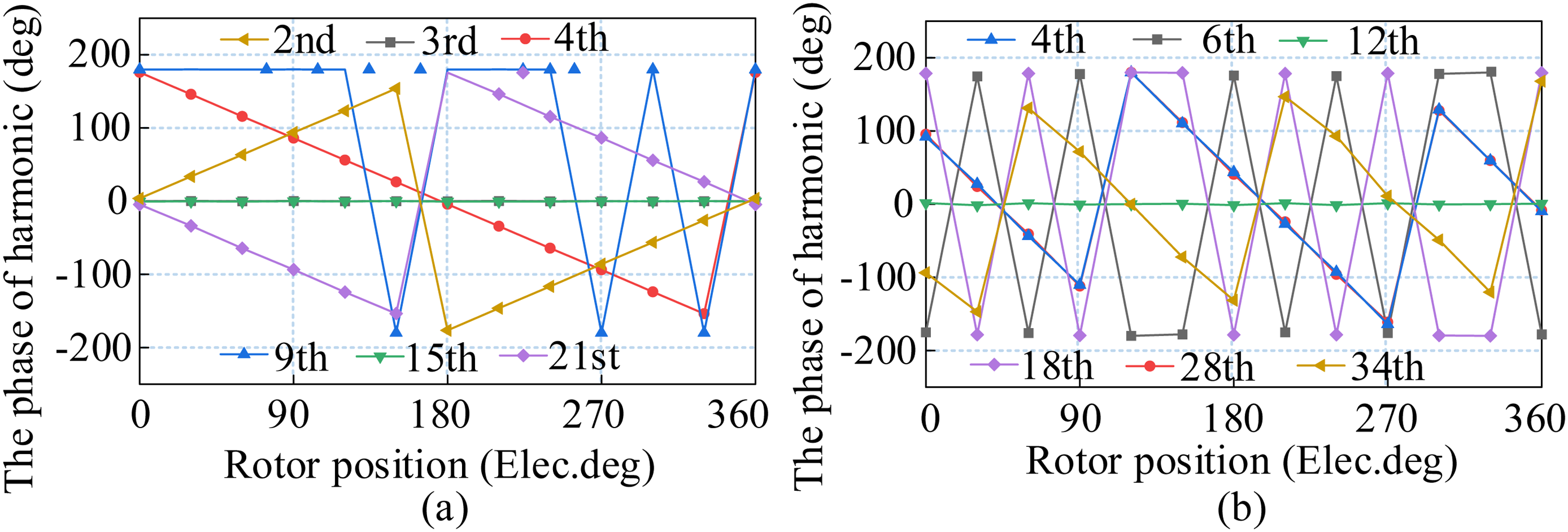
Harmonic angle of the PM field varies with rotor position. (a) Inner motor. (b) Outer motor.
The key working harmonics identified in this research not only produce stable electromagnetic torque but also feature lower orders at correspondingly high rotational speeds. Under identical amplitude conditions, these lower-order harmonics can induce a higher back electromotive force (EMF), thereby contributing to a higher output torque. These findings underscore the importance of prioritizing such working harmonics in motor design, maximizing torque output through the optimization of harmonic distribution within the airgap, hence enhancing motor performance.
Parameter optimization design
Based on the multi-mode performance requirements, this study decomposes the optimization design into sub-objectives tailored to specific modes. For Mode 1, the focus is on optimizing average torque while suppressing torque ripple to ensure energy efficiency during high-speed cruising. For Mode 2, the core objective is to maximize average torque, with appropriate consideration given to torque ripple and the sinusoidal quality of the back-EMF waveform, ensuring smooth operation under high-torque conditions. As a composite mode, Mode 3 can be regarded as a combination of Modes 1 and 2, with its operational performance linked to these two modes. A comprehensive approach is adopted to balance these objectives and determine the optimal solution.
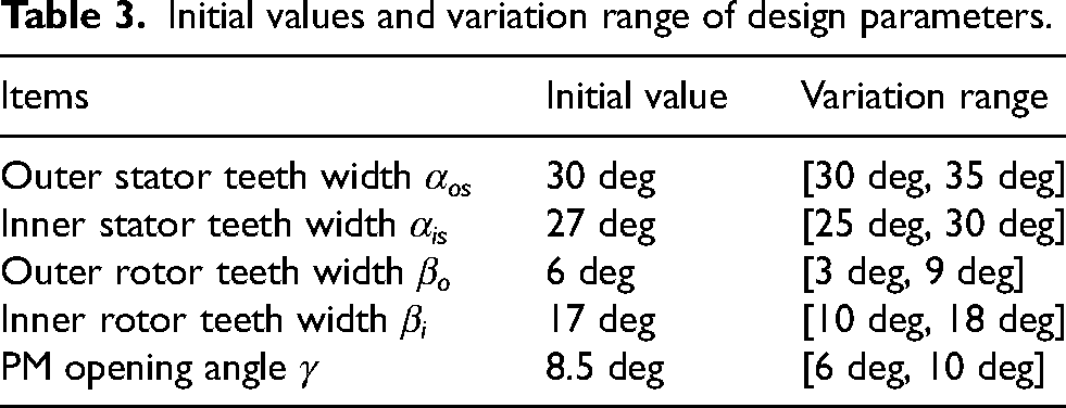
Owing to its unique structure, the motor can be regarded as comprising two independently functioning parts: an inner and an outer motor. Their structural parameters can be separately analyzed, allowing for the optimization of several parameters that significantly impact motor performance. These parameters include the tooth widths of the inner and outer stators, αis and αos, the tooth widths on the inside and outside of the rotor poles, βi and βo, and the opening angle γ of the V-shaped PMs on the outer stator. The corresponding key parameters are illustrated in Figure 5. The initial values and variation ranges of the corresponding design parameters are presented in Table 3.
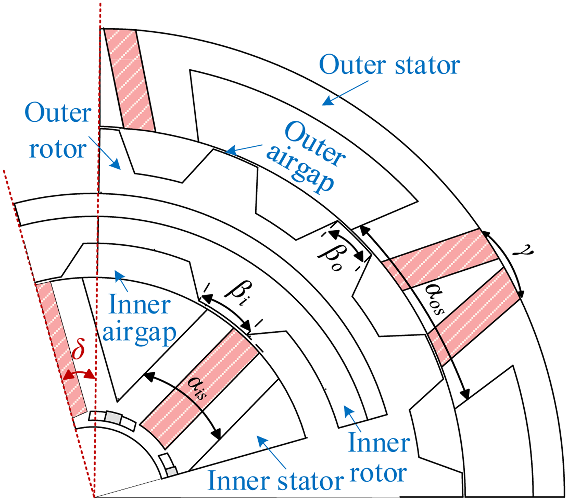
Geometric parameter model of the DSFMPM motor.
Initial values and variation range of design parameters.
Figures 6 and 7 present the correlation between the leading working harmonics of the inner and outer motors and several key design parameters. From Figure 6, in Mode 1, it is observed that the widths of the stator and rotor teeth of the inner motor directly affect the flux density contributed by the leading operational harmonics, particularly the 3rd and 9th harmonics. Meanwhile, Figure 7(a) to (c) demonstrates that, in Mode 2, the stator tooth width, rotor tooth width, and the opening angle of the V-shaped PMs in the outer motor have a direct impact on the flux density produced by the leading operational harmonics, especially the 12th and 18th harmonics.
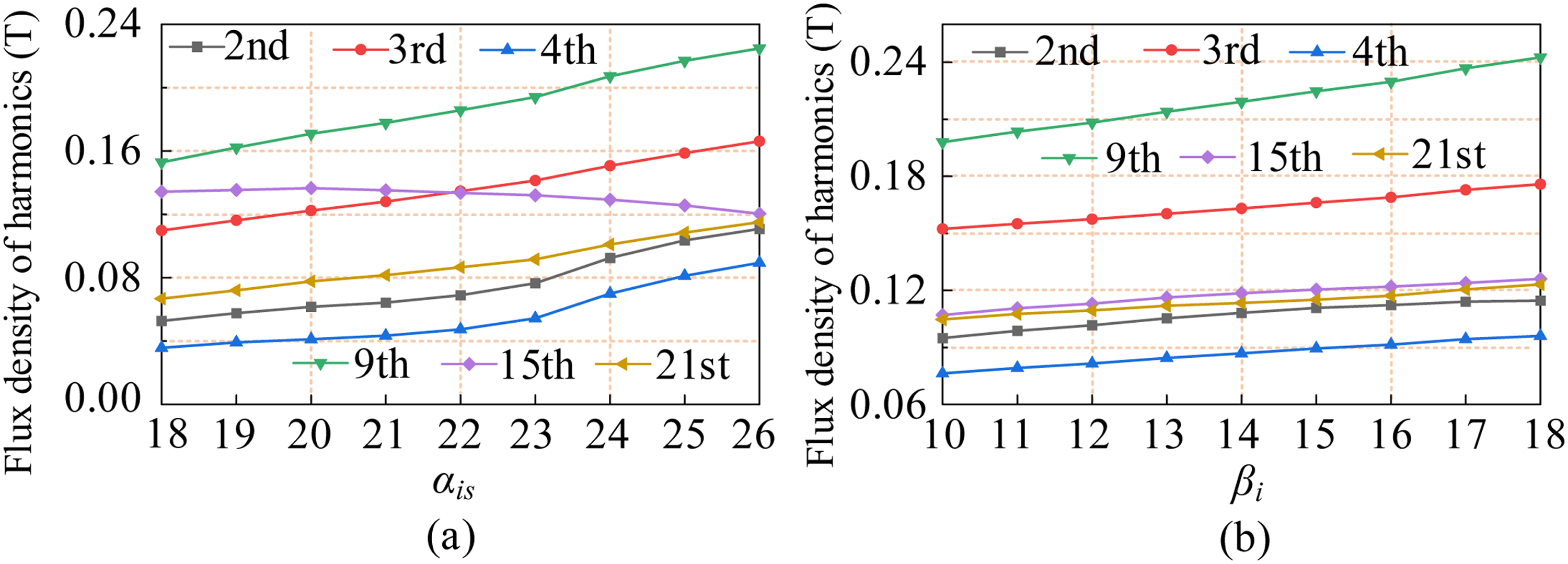
Correspondence between the leading working harmonics and key parameters. (a) Harmonics and αis. (b) Harmonics and βi.
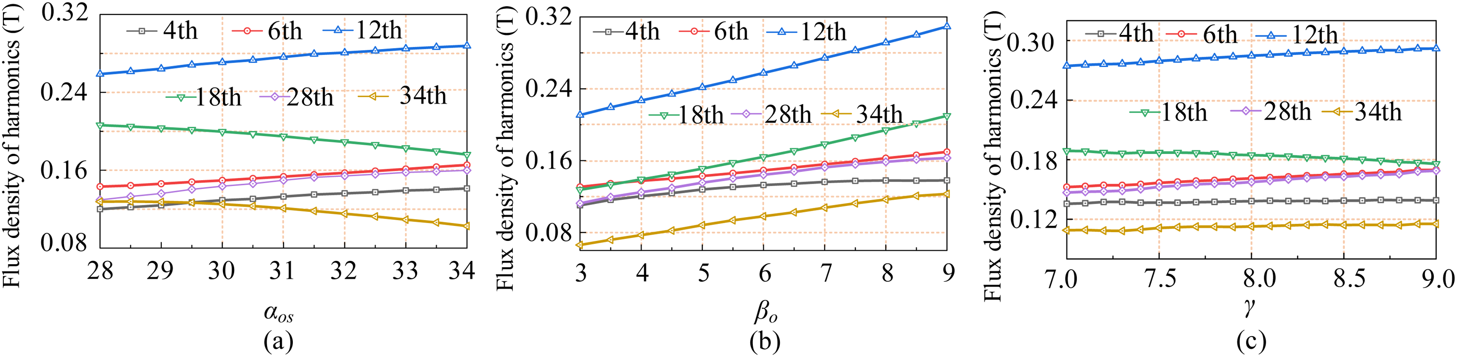
Correspondence between the leading working harmonics and key parameters. (a) Harmonics and αos. (b) Harmonics and βo. (c) Harmonics and γ.
To expedite the identification of the optimal design parameters, the response surface methodology (RSM) was adopted. Based on the harmonic analysis results, five key design variables, namely αis, αos, βi, βo, and γ, were selected due to their significant influence on the leading working harmonics. Within the predefined parameter ranges, a multi-level design of experiments was conducted to generate the sample points for model fitting. For each sample point, two-dimensional FEA was performed to evaluate the electromagnetic responses, including average torque and torque ripple under different operating modes. Using the obtained sample data, second-order polynomial response surface models were established to characterize the relationship between the design variables and performance indices. The general form of the response surface model can be expressed as: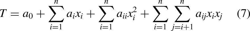

Flowchart of the proposed optimization procedure for the DSFMPM motor.
Based on the fitted response surface model, the influence of different parameter combinations on torque performance can be efficiently evaluated. Figure 9 illustrates the response surfaces of output torque with respect to key design parameters.
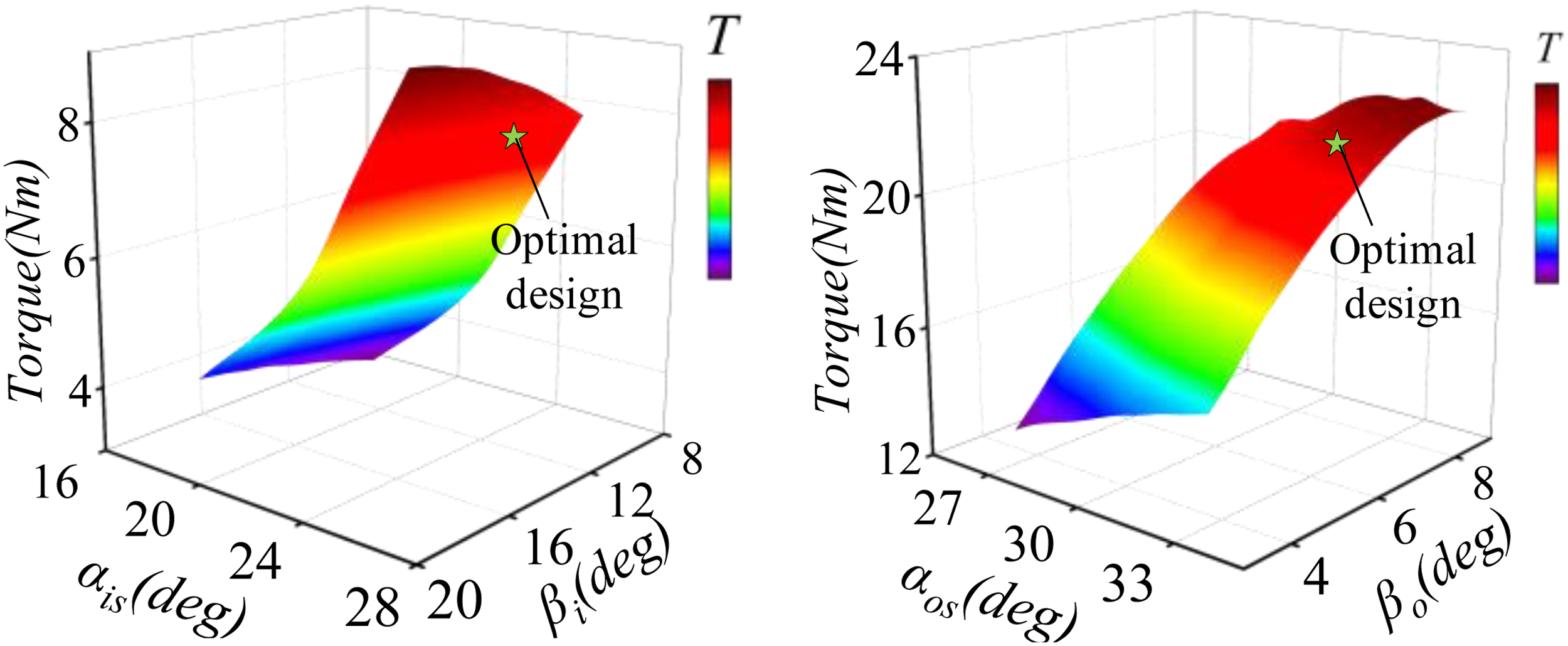
Output torque distribution. (a) Output torque of inner motor versus αis and βi. (b) Output torque of outer motor versus αos and βo.
As shown in Figure 9(a) and (b), the output torque distribution of the inner and outer motors varies significantly with the combinations of stator and rotor tooth widths, indicating strong nonlinear coupling between design variables and torque performance. These response surfaces not only reveal the sensitivity of torque to key parameters but also provide a direct basis for subsequent optimization.
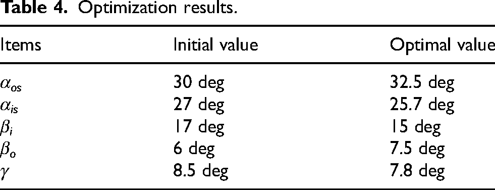
The optimization problem is then solved based on the constructed response surface model, and the optimal parameter combination is obtained. Finally, the optimized design is validated by FEA. The optimal parameters are determined as listed in Table 4. Compared to the motor before optimization, the leading working harmonics of the inner and outer airgaps of the optimal motor have been enhanced, as demonstrated in Figure 10. The results demonstrate that the proposed RSM-based optimization method can effectively improve the torque performance of the motor under multi-mode operation.
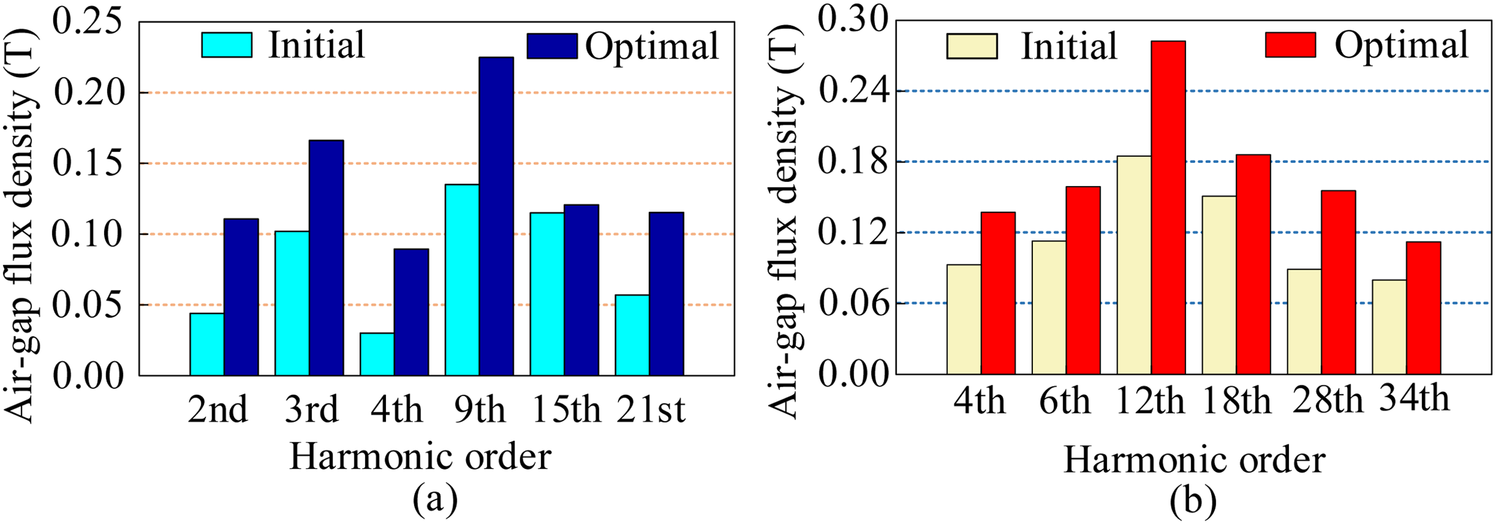
Analysis of the leading working harmonics before and after optimization. (a) Inner motor. (b) Outer motor.
Optimization results.
Performance evaluation
To verify the effectiveness of the motor design and assess the performance of the motor across three modes, the key electromagnetic performances of the DSFMPM motor are analyzed in this section. The magnetic field distributions and flux distributions of the proposed motor in Mode 3 are shown in Figure 11. A comparison of Figures 11(a) and (b) reveals a significant enhancement in the flux density magnitude within both airgaps and the critical regions of the stator/rotor teeth after optimization. This observation indicates that the harmonic-oriented design effectively strengthens the main airgap flux and its modulation, thereby laying a foundation for improved torque output.
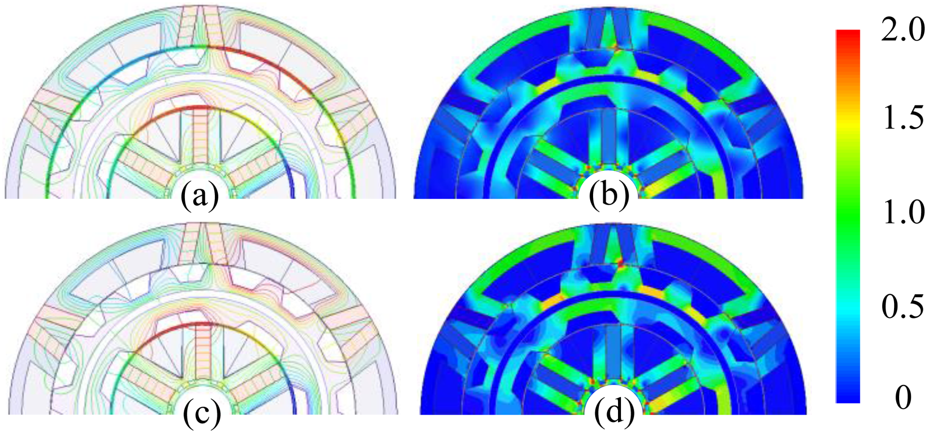
Magnetic field and flux distributions of the proposed DSFMPM motor. (a) Magnetic field distribution of initial motor. (b) Flux distribution of initial motor. (c) Magnetic field distribution of the optimal motor. (d) Flux distribution of the optimal motor.
Figure 12 shows a comparison of the no-load back-EMF waveforms and their harmonic spectra for the inner and outer motors before and after optimization. The optimized back-EMF waveforms exhibit significantly improved sinusoidal shape and symmetry, which is beneficial for brushless AC control and torque ripple reduction. The harmonic spectra confirm that the fundamental amplitude is increased while the total harmonic distortion (THD) is notably suppressed after optimization. This validates the feasibility of improving waveform quality by selectively controlling the working harmonics. Figure 13 shows the output torque waveforms of the motor under the three operation modes at the rated current, comparing the initial and optimized designs. Quantitatively, the average torque increases from 7.7 Nm to 8.8 Nm in Mode 1, from 19.4 Nm to 21.5 Nm in Mode 2, and from 27.3 Nm to 30.4 Nm in Mode 3. Concurrently, the torque ripple in each mode is effectively suppressed. This result provides direct evidence that the parameter optimization based on dominant working harmonics can systematically enhance the torque output capability and operational smoothness of the DSFMPM motor under multi-mode conditions.
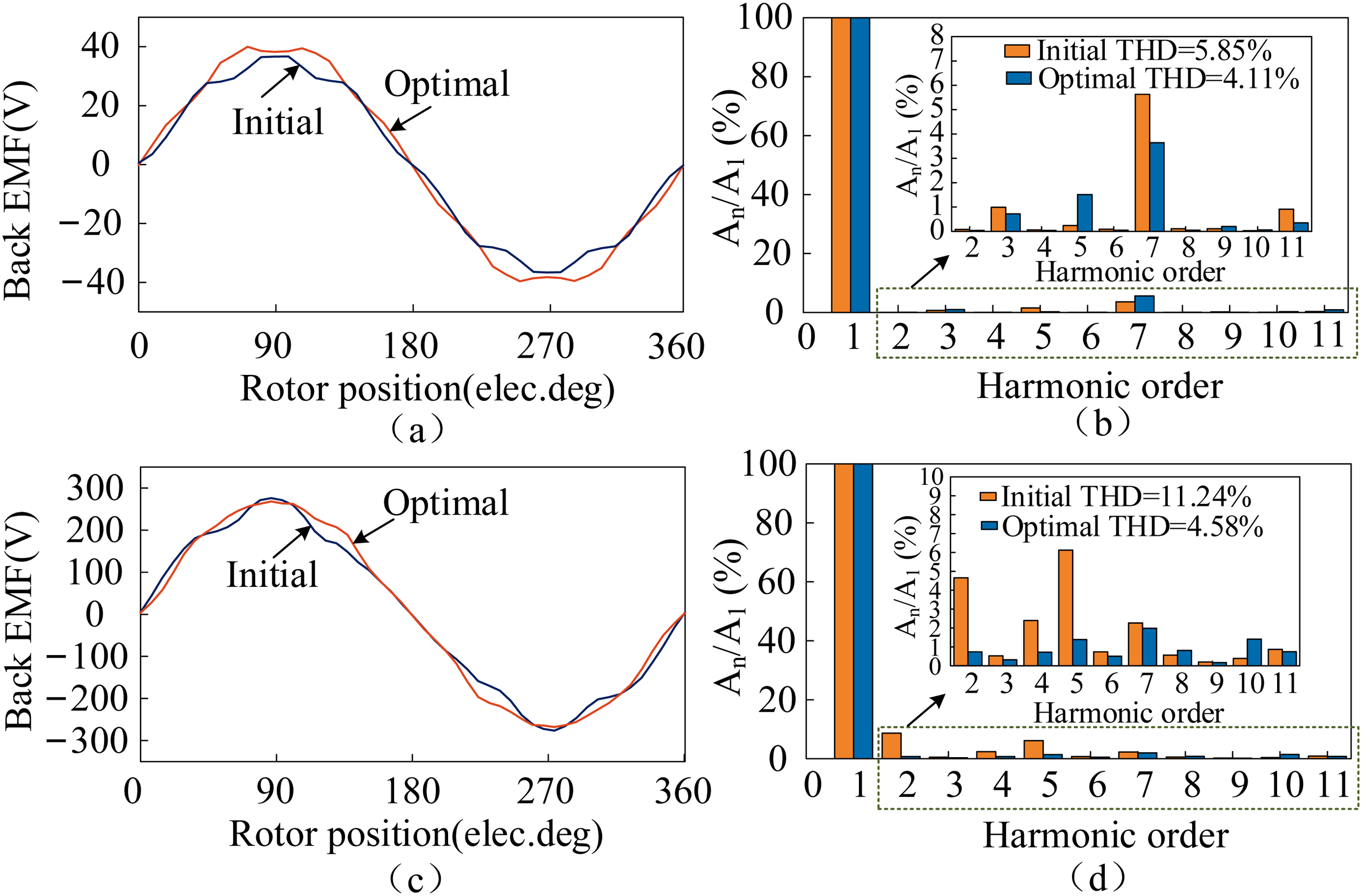
No-load back-EMF analysis. (a) Back-EMF of inner motor and (b) THD analysis of inner motor. (c) Back-EMF of the outer motor. (d) THD analysis of outer motor.
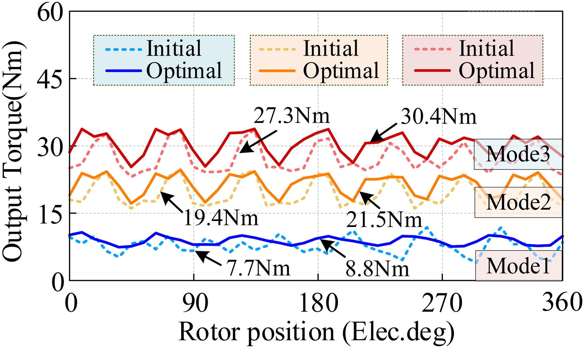
Torque performances of initial and optimal models.
To further validate the performance advantages of DSFMPM motor, a quantitative simulation comparison was conducted with conventional single-airgap FMPM (SA-FMPM) motors and surface-mounted PMSM (SPMSM) motors. The motor models are shown in Figure 14. All comparisons were carried out under unified constraints: the stator outer diameter, core stack length, winding current density, permanent magnet material, and other key parameters were kept identical. The single-stator FMPM retained the outer stator and outer rotor structure of the DSFMPM. The total volume of permanent magnets is the same for both SPMSM and SA-FMPM motors. The performance of each motor was evaluated using finite element simulation under rated operating conditions, and the comparison results are presented in Table 5.
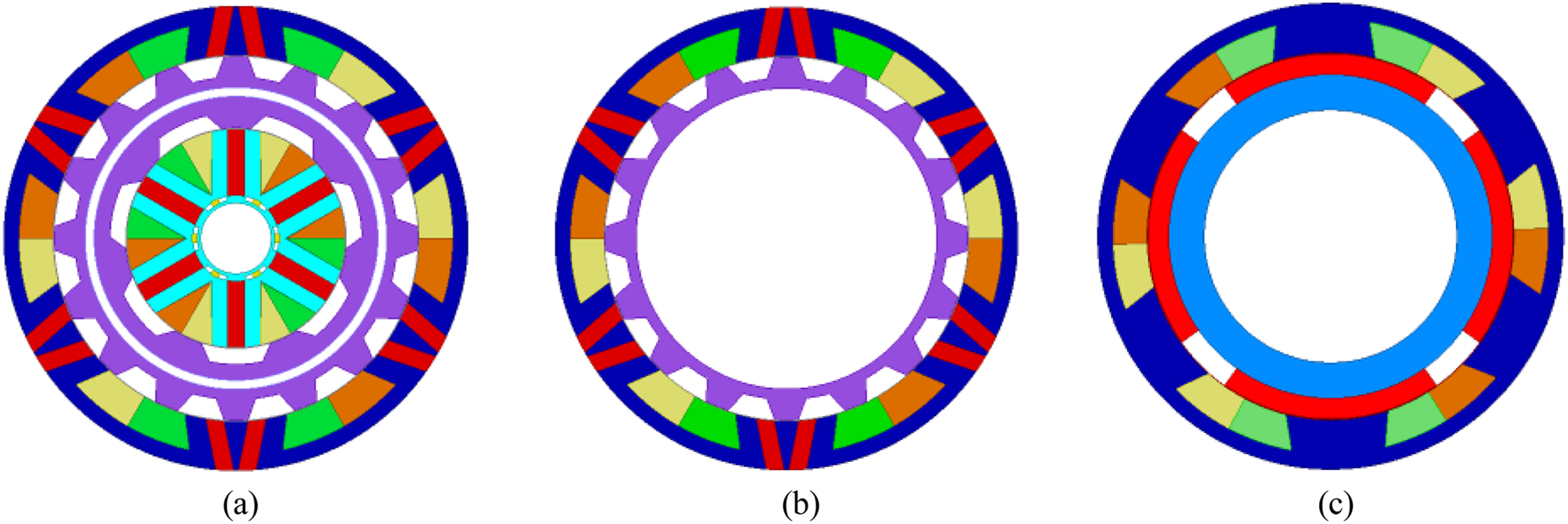
DSFMPM and other motor models. (a) DSFMPM Motor (b) SA-FMPM motor (c) SPMSM motor.
Comparison of electromagnetic performance Among different motor topologies.
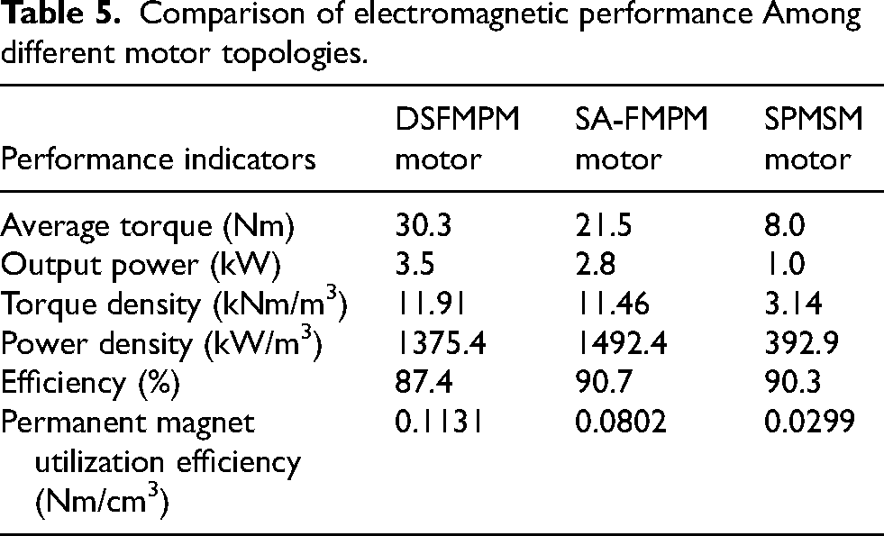
For a fair comparison, the torque density and power density of all compared motors are calculated based on the actual effective motor volume. As shown in Table 5, the torque density of the proposed DSFMPM motor reaches 11.91 kNm/m3, significantly outperforming conventional SPMSM under the same constraints and slightly higher than that of the SA-FMPM motor. This is the result of the torque superposition effect of the dual-airgap topology combined with the harmonic-oriented optimization's enhancement of the main working harmonic flux density. Additionally, the permanent magnet utilization rate of the dual-stator motor is higher than that of the SA-FMPM motor and far exceeds that of SPMSM motor. In terms of efficiency and operational performance, the DSFMPM motor, due to its two sets of windings, has a slightly lower rated efficiency compared to the other two motors. This difference is primarily caused by the copper losses in the dual-winding setup. However, the concentrated winding design adopted for both the inner and outer motors minimizes the winding end length, thereby reducing copper losses.
In addition, the proposed DSFMPM motor can operate in three modes with independent or coordinated excitation of the inner and outer stators, enabling it to adapt to various driving conditions of electric vehicles. This capability is unattainable with the SA-FMPM motor or the traditional SPMSM motor, thus offering superior operational adaptability.
Experimental validation
To verify the effectiveness of the proposed harmonic-oriented design method and the performance of the optimized DSFMPM motor in practical operation, a prototype motor was manufactured and tested according to the optimized key parameters. Figure 15 shows the core components of the prototype, including the outer stator, inner stator, and middle rotor.
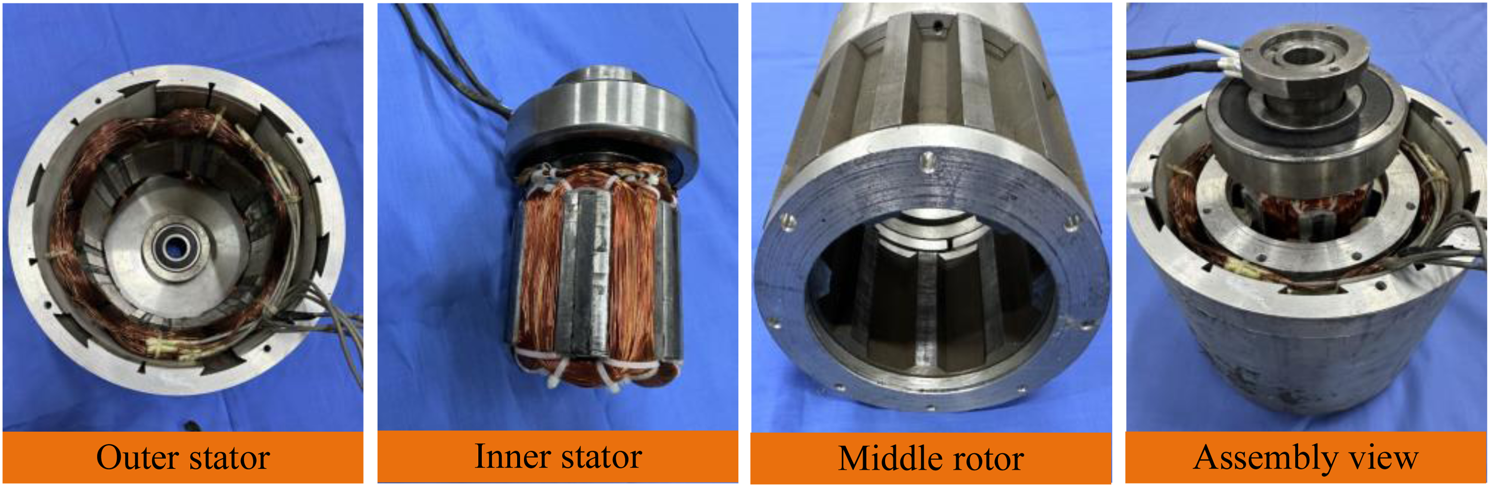
The components of the DSFMPM motor.
The experimental platform is illustrated in Figure 16. A magnetic powder brake was employed to simulate various load conditions, and a torque sensor was used to measure the output torque and rotational speed. A high-performance dSPACE controller was adopted to regulate the currents in the inner and outer stator windings. The average torque under different load conditions was obtained from the load controller.
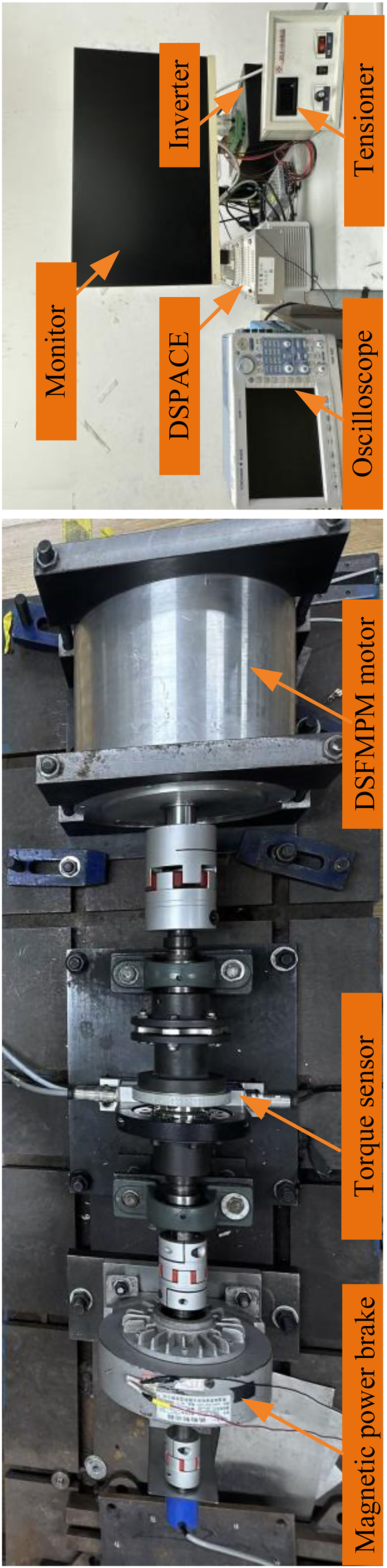
Experimental test platform of the prototype motor.
Figure 17 depicts the measured no-load back-EMF waveforms of the motor at 600 r/min. The three-phase back-EMF waveforms of the outer motor exhibit high sinusoidal quality, balanced amplitude, and favorable symmetry, which are consistent with the optimized waveform characteristics predicted by simulation. Affected by manufacturing factors such as winding assembly deviation and rotor-stator coaxiality error, the back-EMF waveforms of the inner motor show slight amplitude imbalance and reduced phase symmetry. These experimental results objectively reflect the machining and assembly errors in small-batch prototyping.
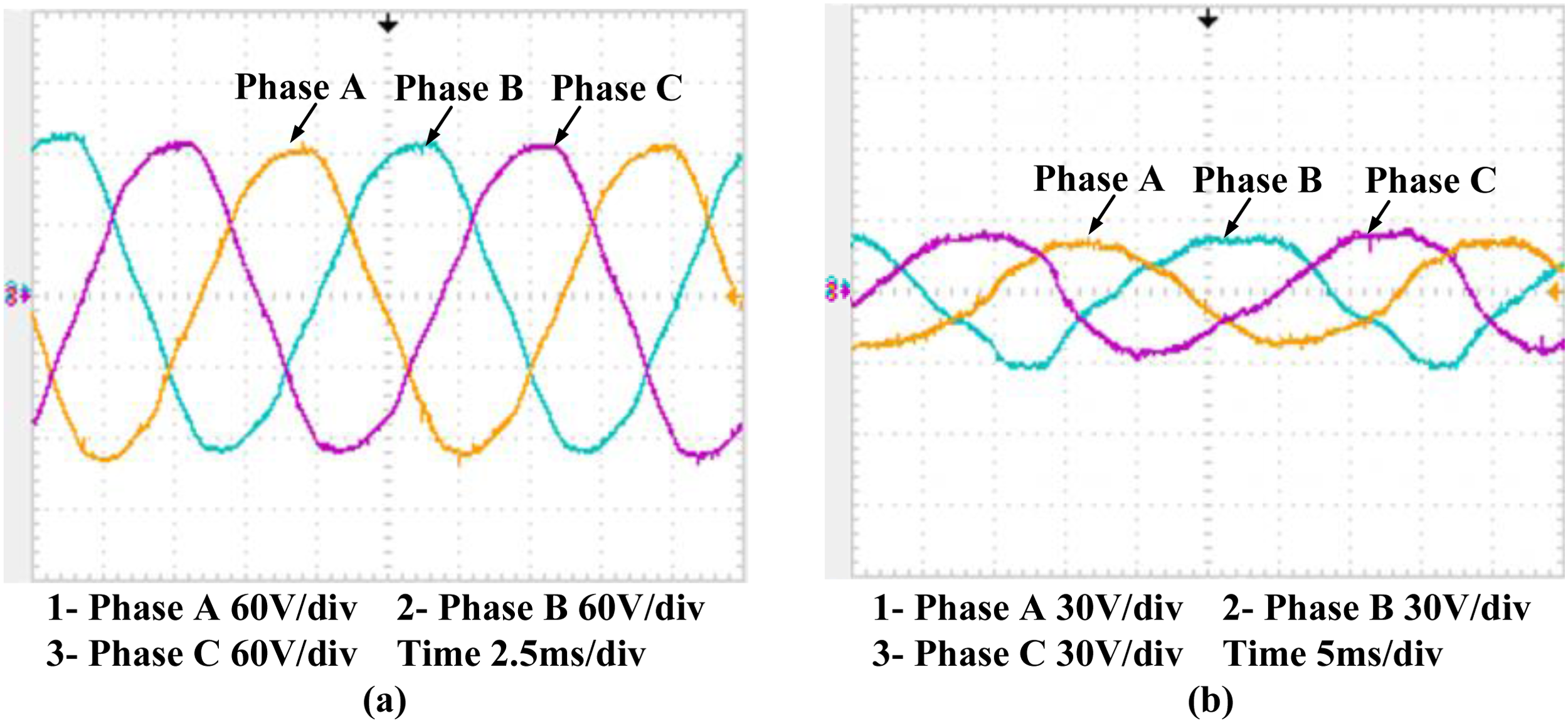
Measured no-load back-EMF waveforms of the DSFMPM motor. (a) Outer windings. (b) Inner windings.
To evaluate the load performance of the proposed motor, torque output tests were conducted under various operating conditions. Figure 18 shows the measured steady-state output torque waveforms of the DSFMPM motor prototype under three operating modes. In Mode 1, the inner motor operates independently with stable speed and torque output. Figure 18(b) presents the torque waveform in Mode 2, where the outer motor runs alone and delivers higher average torque with smooth operation. Figure 18(c) illustrates the cooperative operation in Mode 3, in which the torque components produced by the inner and outer airgaps are superimposed to achieve the maximum output torque. The measured results show the same variation trend as the simulation results. In summary, the experimental results verify the feasibility and control flexibility of the proposed motor, and confirm the effectiveness of the harmonic-oriented optimization design.
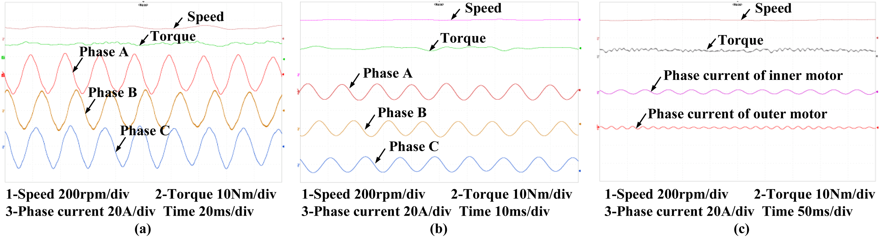
Steady-state output torque waveforms of the DSFMPM motor. (a) Mode 1. (b) Mode 2. (c) Mode 3.
Conclusion
In this paper, a harmonic-oriented design and optimization method is proposed for dual-airgap FMPM motors to improve torque performance under multi-mode operation. Based on the airgap field modulation theory, the dominant working harmonics contributing to torque generation are identified in the inner and outer airgaps, and the relationship among harmonics, structural parameters, and output torque is revealed. The RSM is adopted to perform multi-objective optimization on key parameters such as stator and rotor tooth widths and PM opening angle, which effectively enhances the amplitude of dominant harmonics and optimizes the back-EMF waveform. Simulation analysis and prototype experiments demonstrate that the optimized motor achieves improved torque performance and stable operation in the three operating modes. This study provides an effective reference for the multi-condition optimization design of high-performance dual-stator motors.
Footnotes
Acknowledgment
This work was supported in part by the National Natural Science Foundation of China International Cooperation Key Project under Grants 52320105009 and in part by the National Natural Science Foundation of China's major project sub-project under Grants 51991385. The authors would like to thank Zhaoyi Li and Yikun Sun for their help with the simulations and experiments in this work.
Ethical approval
Not applicable.
Funding
The authors received no financial support for the research, authorship, and/or publication of this article.
Declaration of conflicting interests
The authors declared no potential conflicts of interest with respect to the research, authorship, and/or publication of this article.