
Abstract
Wired campus networks based on optical fiber and twisted pair usually suffer from limited coverage, poor security, and decentralized management. In order to expand the network coverage and provide more secure, convenient, and centrally manageable mobile access services, more and more campus are adopting the controller architecture to transform their campus wireless local area networks on the basis of the original campus wired network. In engineering practice and scientific research, researchers usually face problems such as insufficient network equipment and difficult integration of hardware and software. Based on this background, this research integrates key technologies, such as wireless local area network, software-defined network, network simulation, virtual local area network, and dynamic host configuration protocol, and designs a novel wireless local area network simulation project based on dual-controller architecture of “software-defined network controller + wireless local area network controller,” and describes its realization process in detail. After testing, the wireless local area network simulation project designed in this paper runs stably and the software-defined network controller runs normally. This research is helpful in understanding the working principle of wireless local area network and software-defined network, and also helps to understand the application scenarios of key technologies, such as wireless local area network and software-defined networks, in campus networks, as well as to master the process of designing and realizing them, which provides useful references for the majority of network engineers and technicians.
Keywords
Introduction
Research background
Infrastructures such as transmission media and network equipment play a key role in campus networks.
1
Traditional campus networks mainly use wired transmission media such as optical fibers and twisted pairs,
2
and although these wired networks can meet the basic communication needs, they also have some limitations, such as limited coverage and difficulties in upgrading and transformation. In addition, traditional network equipment usually adopts an integrated architecture of control plane and data forwarding plane,
3
as shown in Figure 1, which requires network administrators to manually manage the equipment one by one. This management method has problems such as low efficiency, heavy workload, not easy to scale, and troubleshooting difficulties. With the increase in the number of network devices, this management method can no longer adapt to the flexibility and complexity needs of modern networks.
4
To cope with these challenges, early campus networks are in urgent need of technology updates and equipment upgrades to meet new teaching and research needs. Some campus have begun to explore new network technologies and solutions, such as wireless local area network (WLAN)
5
and software-defined network (SDN).
6
Architecture comparison between SDN and traditional networks.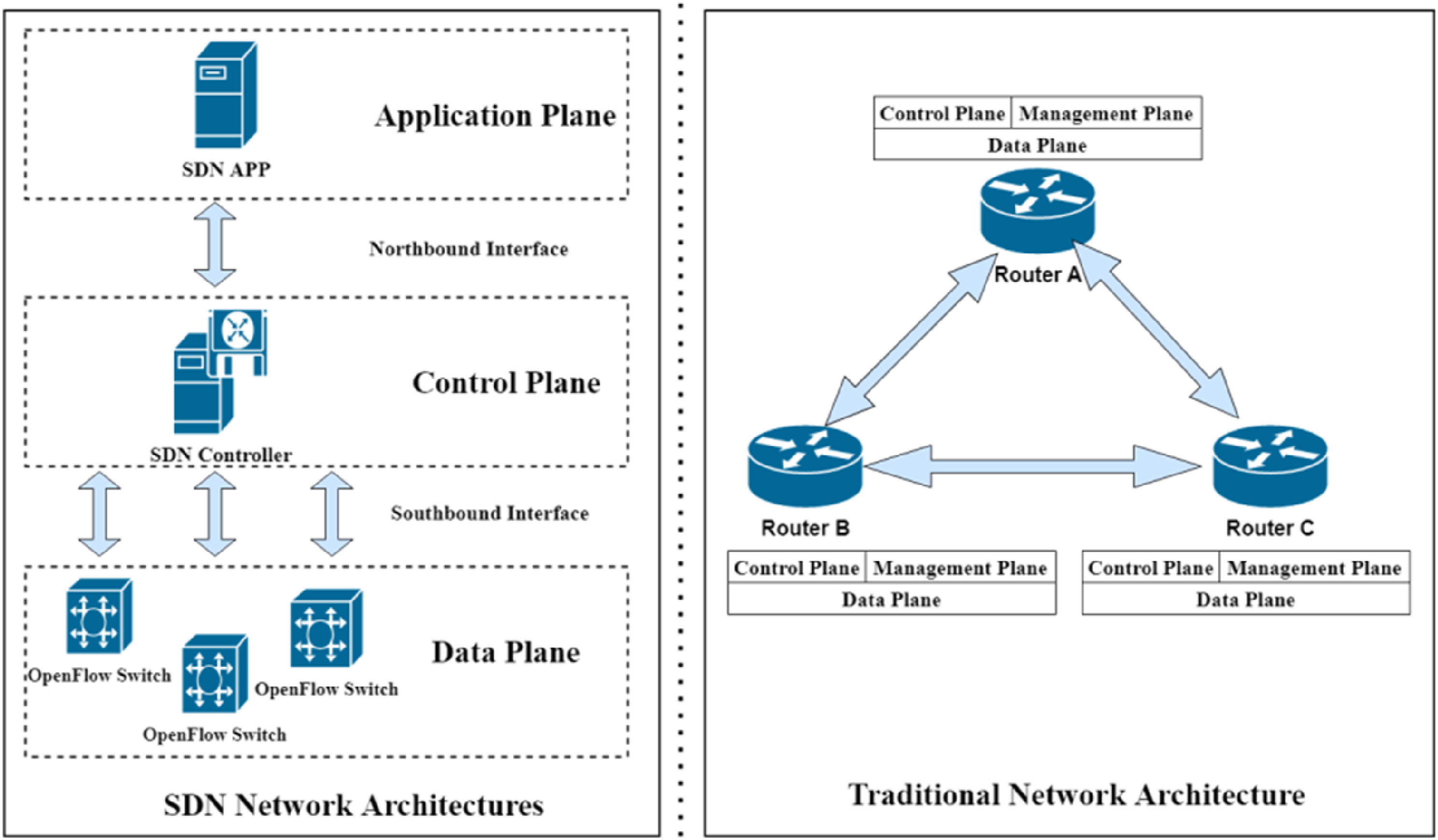
As an extension of wired local area network (LAN), WLAN is a data transmission system constructed using radio frequency technology, which can realize convenient wireless communication. 7 Compared with wired LAN, WLAN has the advantages of mobility, easy installation, wide coverage, easy expansion, high reliability, and economic savings, so WLAN has become the preferred network access solution for campus networks. 8 SDN is a new type of network architecture and management method, which better solves the shortcomings of traditional network management. By separating the control plane and data plane, SDN centralizes the network control to one or more controllers,9,10 realizing flexible control of network traffic and dynamic management of network policies, 11 as shown in Figure 1. SDN has the advantages of flexibility, programmability, scalability, advanced service support, and network security, 12 which provides a modern network with more efficient, flexible, and secure solution for modern networks. 13
Significance of the research
WLAN simulation based on SDN and WLAN controller (WLC) is an advanced network simulation methodology. SDN allows network administrators to dynamically and centrally manage network traffic, 14 while WLC is responsible for centrally managing the connectivity of wireless access points (APs) and end devices. 15 Combining the two for WLAN simulation research is of significant significance: (1) With the SDN architecture, the control and management of network traffic is more flexible, and administrators can optimize network performance by adjusting network configurations and policies in a timely manner according to network demands. (2) As a centralized controller, WLC manages multiple APs and dynamically adjusts wireless network parameters, such as channel assignment, power control, and load balancing, to improve network throughput and coverage. (3) The centralized control of SDN helps implement a unified security policy to ensure data security and privacy protection. (4) By working together, SDN and WLC can better monitor and optimize network performance, predict and resolve potential network bottlenecks, and improve user experience. This emulation approach is suitable for enterprise and campus networks, as well as places that require high availability and flexibility, such as hospitals and industrial environments.
Scenario requirements
This research takes a small and medium-sized campus network as an example. In order to provide teachers and students with a wide coverage, convenient, and secure WLAN access service, a WLC is planned to be deployed in the data center, through which multiple decentralized APs are centrally managed to achieve centralized configuration, monitoring, and troubleshooting of the WLAN. A number of APs are distributed in different buildings and floors to provide teachers and students with different service set identifiers (SSIDs) to meet the access needs of different user groups. 16 The physical network is divided into multiple logical subnets by dividing the virtual local area network (VLAN) to isolate the broadcast domain and improve the security and manageability of the network.
We plan to deploy an SDN controller in the data center and use the SDN controller to perform visual and centralized management of the devices in the campus network. As the control center of the network, the SDN controller is also responsible for dynamically adjusting network traffic and resource allocation according to the network policy, thus improving network efficiency and reliability, and improving the deficiencies of traditional network management methods.
The project planning
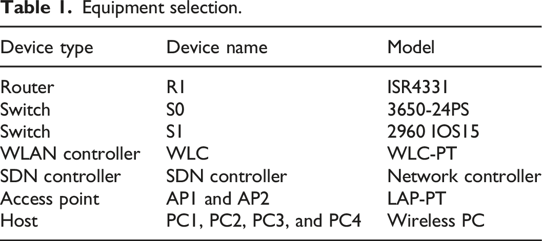
Equipment selection planning
Equipment selection.
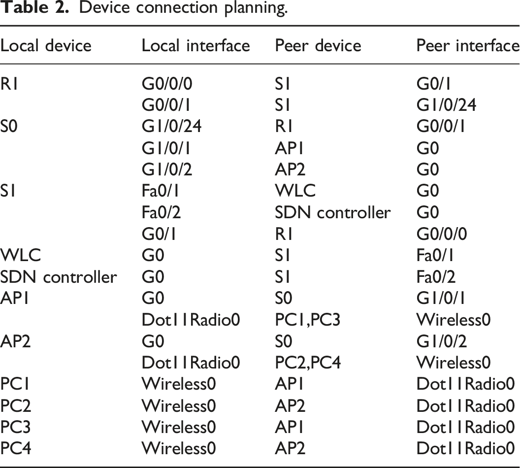
Device connections planning
Device connection planning.
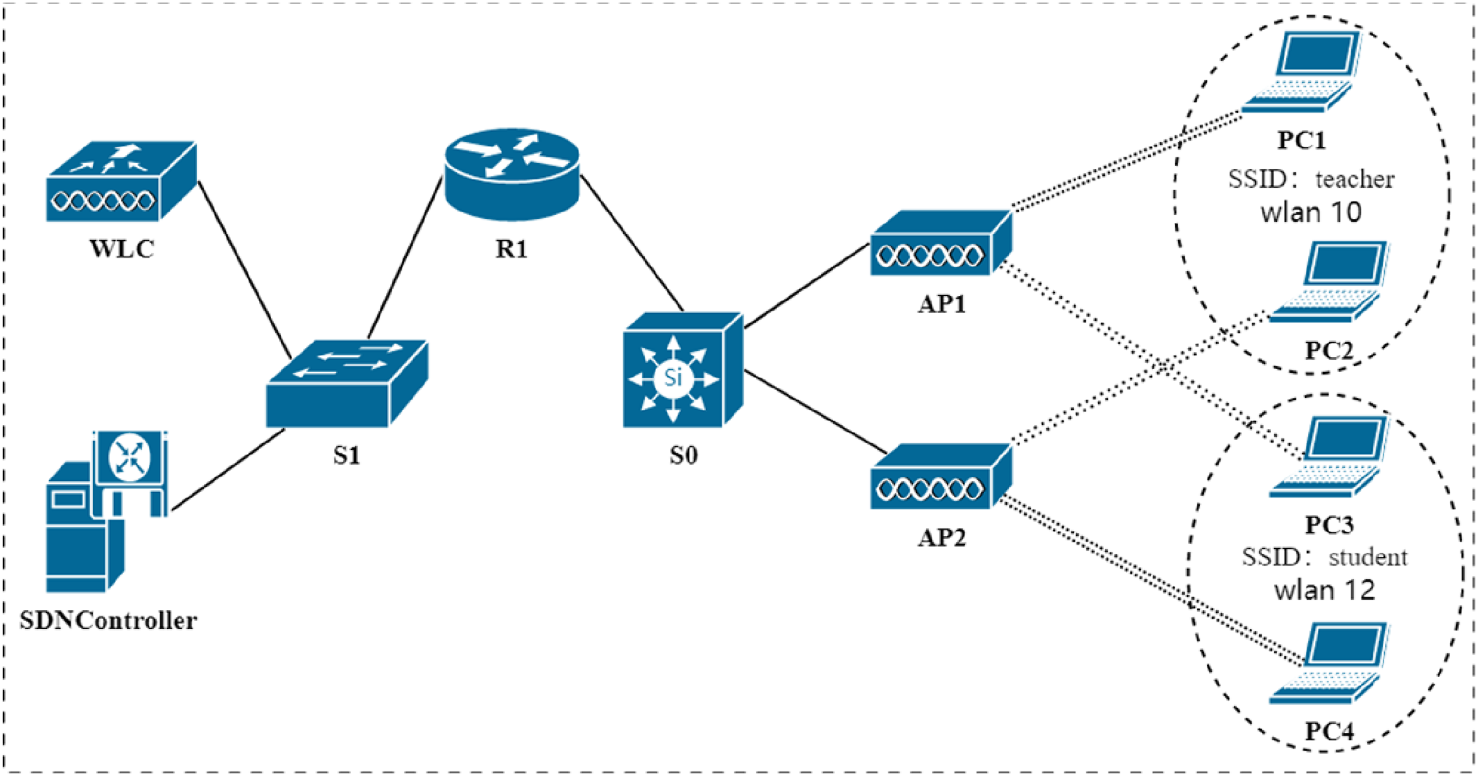
Project topology.
Wireless planning
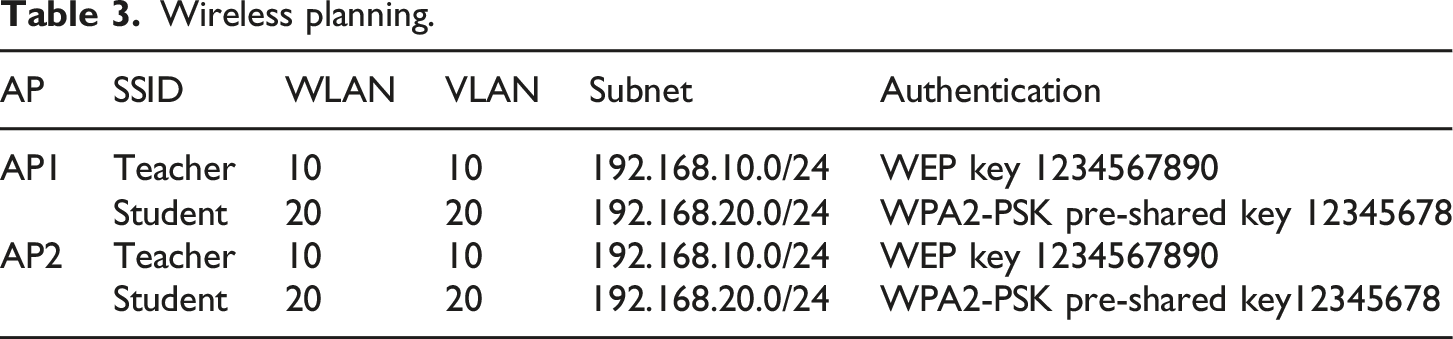
Wireless planning.
Device interface, IP address, and gateway planning
Configure the link between Router R1’s G0/0/1 and Switch S0’s G1/0/24 as an 802.1Q Trunk and transmit all VLAN traffic over this trunk link. Create sub-interfaces G0/0/1.10 and G0/0/1.20 on the G0/0/1 interface of Router R1, encapsulate dot1q 10 and dot1q 20 on these two sub-interfaces, respectively, and configure the IP addresses 192.168.10.254/24 and 192.168.20.254/24, which are the IP gateway corresponding to the VLAN 10 and 20. The G1/0/1 and G1/0/2 of switch S0 also need to be configured as an 802.1Q Trunk.
For management purposes, the switch virtual interface (SVI) of switch S0 is configured with IP addresses 10.0.0.2/8 and gateway 10.0.0.1/8. The SVI interface of switch S1 is configured with IP addresses of 192.168.8.253/24 and gateway of 192.168.8.254/24. AP1, AP2, PC1, PC2, PC3, PC4, and other devices dynamically obtain IP addresses using a dynamic host configuration protocol (DHCP). 17
Interface, IP address, and gateway planning for devices.
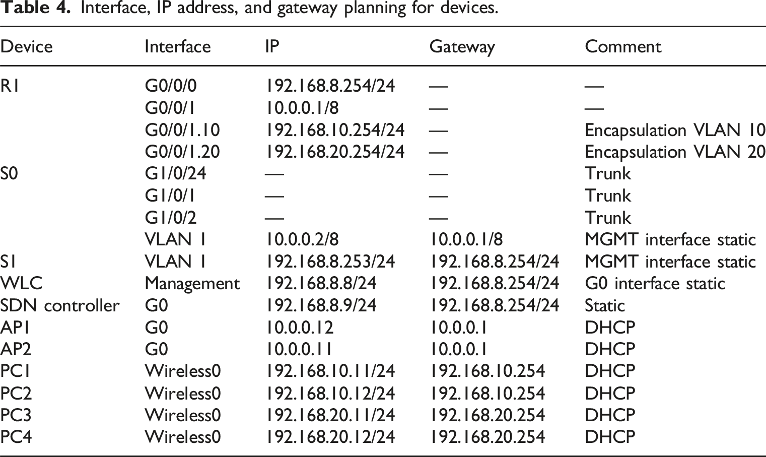
Interfaces G1/0/24, G1/0/1, and G1/0/2 of Switch S0 are operating in switching mode, not routing mode, and do not need to be configured with IP addresses/subnet masks and gateways, so they are indicated by short horizontal lines.
SDN function design
This project designs a visual network management system based on SDN and WLC and implements the main functions of this system based on the northbound interface API provided by the SDN controller, and the division of the main functional modules is shown in Figure 3. Main functional modules.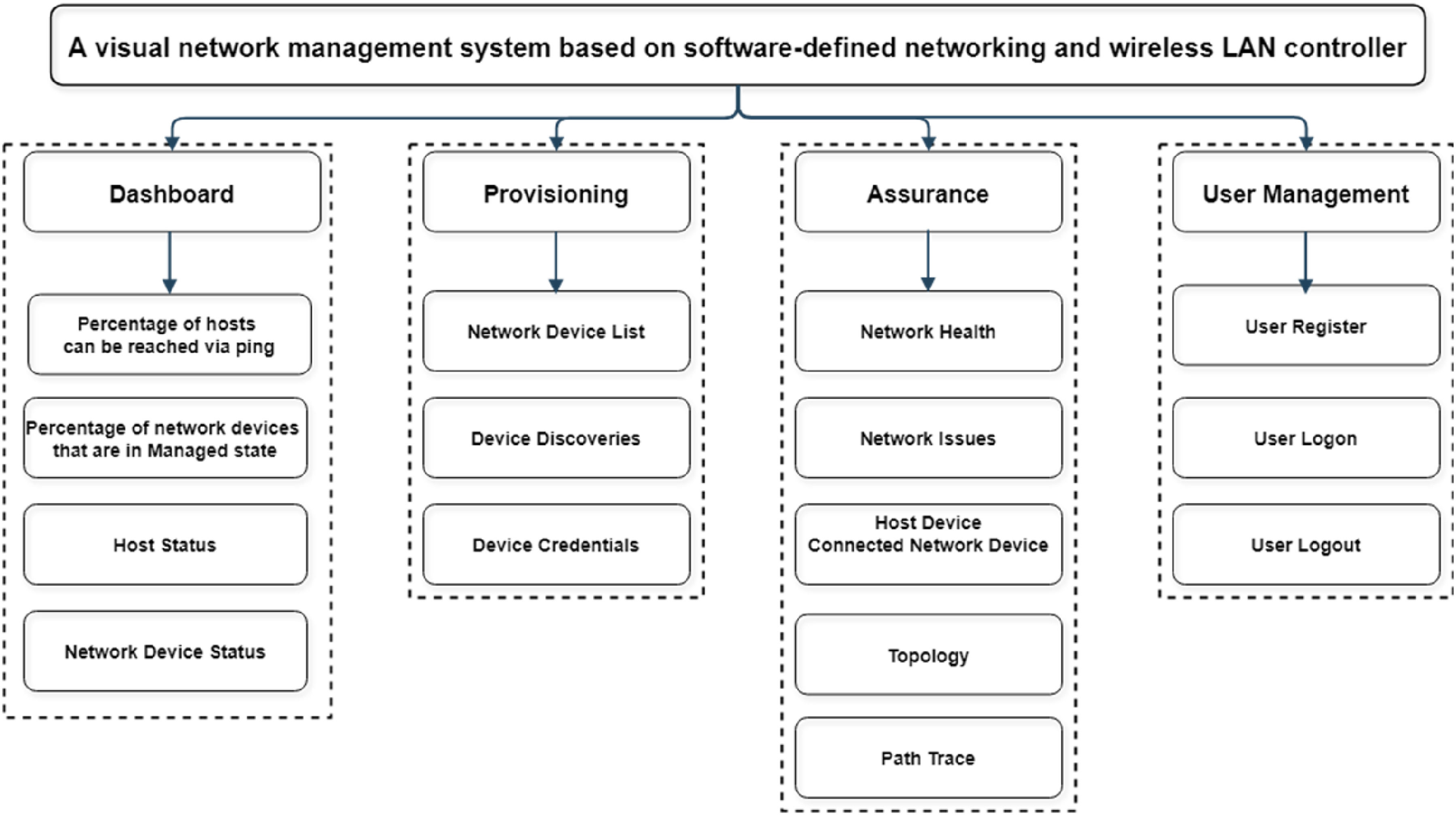
The main functional modules include: (1) Dashboard module: The Dashboard module, which includes viewing the network status and related information to help users quickly identify and troubleshoot problems, includes information such as the percentage of hosts that can be reached via Ping, the percentage of network devices that are in a managed state, the status of hosts in the network, and the status of devices in the network; (2) Provisioning module: The Provisioning module includes the network device list, device discovery, and device credentials functions. Network device list function: Add, delete, change, and select devices in the network. Device discovery function: When a network device is added and configured in the network, the system automatically discovers the new network device and displays it on the page or the device can be added manually. Device credentials function: Manage security credentials between SDN controllers and network devices; (3) Assurance module: The Assurance module includes functions such as network health status, network issue list, host device and connected network device, topology, and path trace.
Project implementation process
Network topology construction
As shown in Figure 2, Table 1, and Table 2, the simulation platform was utilized to select appropriate transmission media and network equipment, construct the network topology, and ensure that the physical connections of the network equipment were normal. Through the simulation platform, it was easy to test and verify the new network design and strategy.
Basic network implementation
(1)Router R1 script: ip dhcp excluded-address 192.168.10.1192.168.10.10 //Excluding 192.168.10.1–192.168.1.10 ip dhcp excluded-address 192.168.10.254 //Excluding 192.168.10.254 ip dhcp excluded-address 192.168.20.1192.168.20.10 //Excluding 192.168.20.1–192.168.20.10 ip dhcp excluded-address 192.168.20.254 //Excluding 192.168.20.254 ip dhcp excluded-address 10.0.0.1 10.0.0.10 //Excluding 10.0.0.1–10.0.0.10 ip dhcp pool vlan10 //Create vlan10 address pool network 192.168.10.0255.255.255.0 //Corresponds subnet 192.168.10.0/24 default-router 192.168.10.254 //Corresponding gateway 192.168.10.254 ip dhcp pool vlan20 //Create vlan20 address pool network 192.168.20.0255.255.255.0 //Corresponds subnet 192.168.20.0/24 default-router 192.168.20.254 //Corresponding gateway 192.168.20.254 ip dhcp pool ap //Create ap address pool network 10.0.0.0255.0.0.0 //Corresponds subnet 10.0.0.0/8 default-router 10.0.0.1 //Corresponding gateway 10.0.0.1 option 43 ip 192.168.8.8 //Add option 43, and specify the WLC as 192.168.8.8 interface GigabitEthernet0/0/0 ip address 192.168.8.254 255.255.255.0 //Configuring 192.168.8.254/24 interface GigabitEthernet0/0/1 ip address 10.0.0.1255.0.0.0 //Configuring 10.0.0.1/8 interface GigabitEthernet0/0/1.10 encapsulation dot1Q 10 //Encapsulation 802.1Q 10 ip address 192.168.10.254 255.255.255.0 //Configuring 192.168.10.254/24 interface GigabitEthernet0/0/1.20 encapsulation dot1Q 20 //Encapsulation 802.1Q 20 ip address 192.168.20.254 255.255.255.0 //Configuring 192.168.20.254/24 (2)Switch S1 script: interface Vlan1 //Vlan1 SVI interface ip address 192.168.8.253 255.255.255.0 //Configuring 192.168.8.253/24 ip default-gateway 192.168.8.254 //Configuring gateway192.168.8.254 (3)Switch S0 script: Vlan 10 //Create vlan 10 Vlan 20 //Create vlan 20 interface GigabitEthernet1/0/1 switchport mode trunk //Configure G1/0/1 as trunk interface GigabitEthernet1/0/2 switchport mode trunk //Configure G1/0/2 as trunk interface GigabitEthernet1/0/24 switchport mode trunk //Configure G1/0/24 as trunk interface Vlan1 //Vlan1 SVI interface ip address 10.0.0.2255.0.0.0 //Configuring 10.0.0.2/8 ip default-gateway 10.0.0.1 //Configuring gateway 10.0.0.1
Wireless network implementation
According to the planning shown in Table 3, within the wireless LANs page on the WLC, create a new WLAN 10 with the SSID teacher, corresponding to VLAN 10, selecting the authentication method according to the need. In this project, select WEP, the key is 1234567890, and the Central Control selects the local switching-local authentication, as shown in Figure 4. Wireless LANs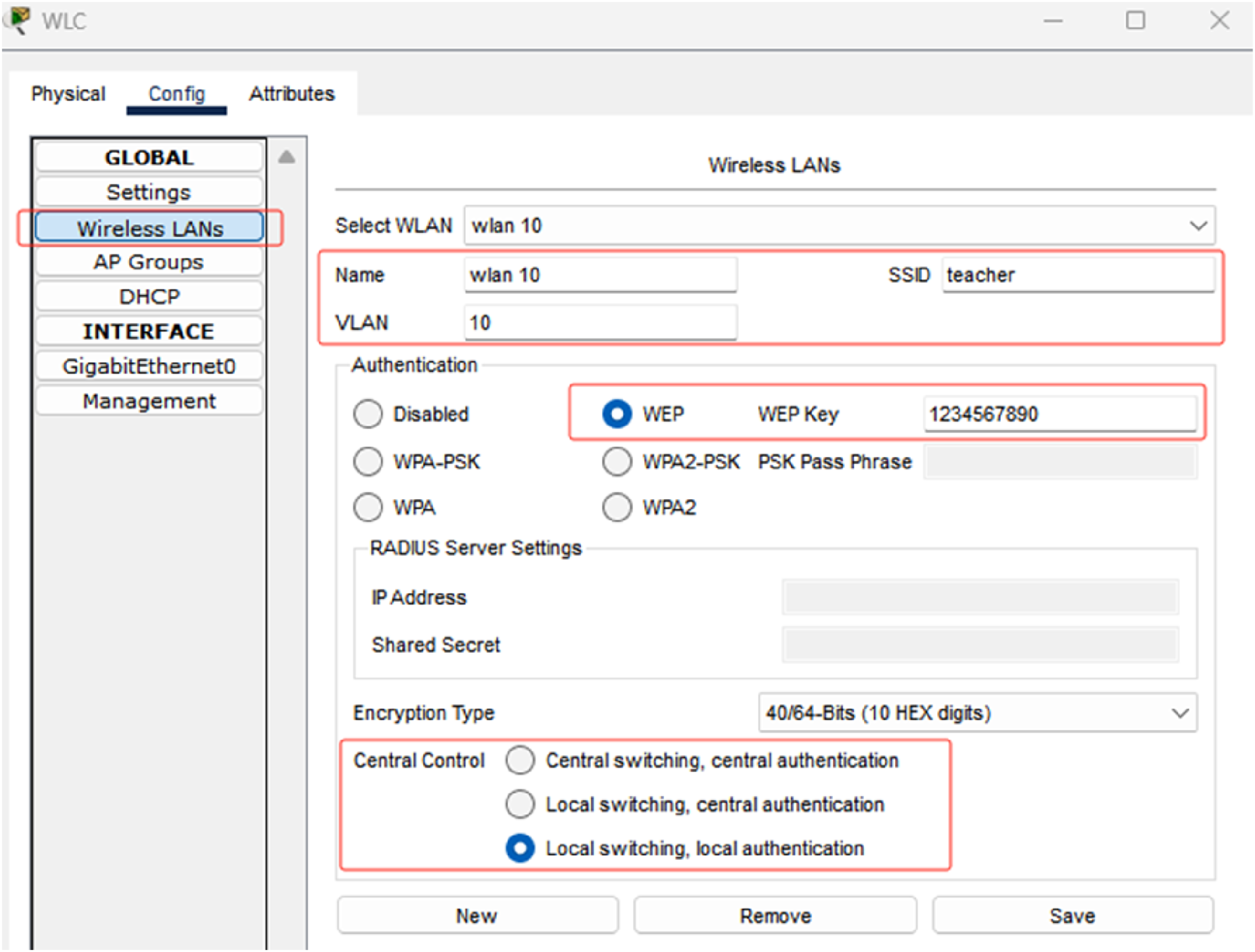
Similarly, create WLAN 20 with SSID student, corresponding to VLAN 20, select the authentication method according to the need, in this project, select WPA2-PSK, the pre-shared key is 12345678, and the Central Control selects local switching-local authentication.
According to the planning shown in Table 3, within the AP groups page on the WLC, the default group, WLAN 10, and WLAN 20 have been added to the default group. It is also possible to create a new group of access points and decide which WLANs will be added to the group, if desired. The name, MAC address, and online status of the access point are shown in the access point box in Figure 5. AP groups.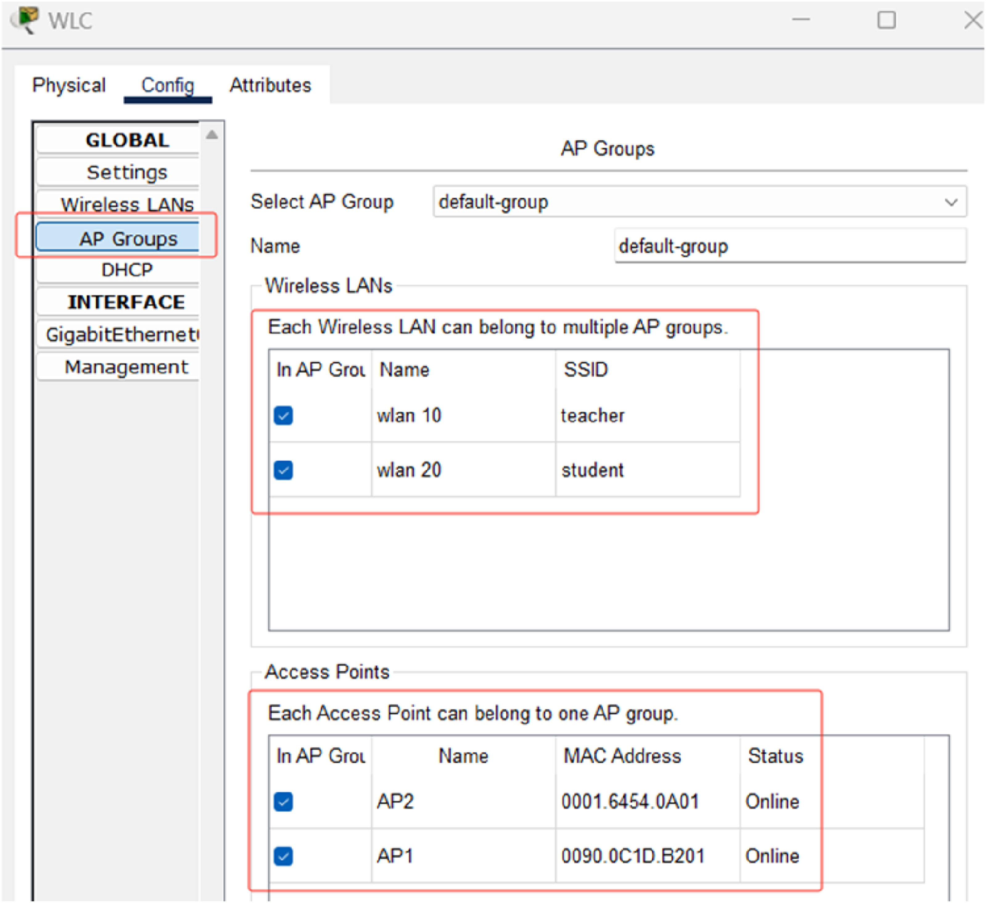
SDN implementation
On the controller page of the SDN controller, check “Access Enabled” to enable the real-world access function of the SDN controller with HTTP Port 58,000, as shown in Figure 6. SDN controller configuration.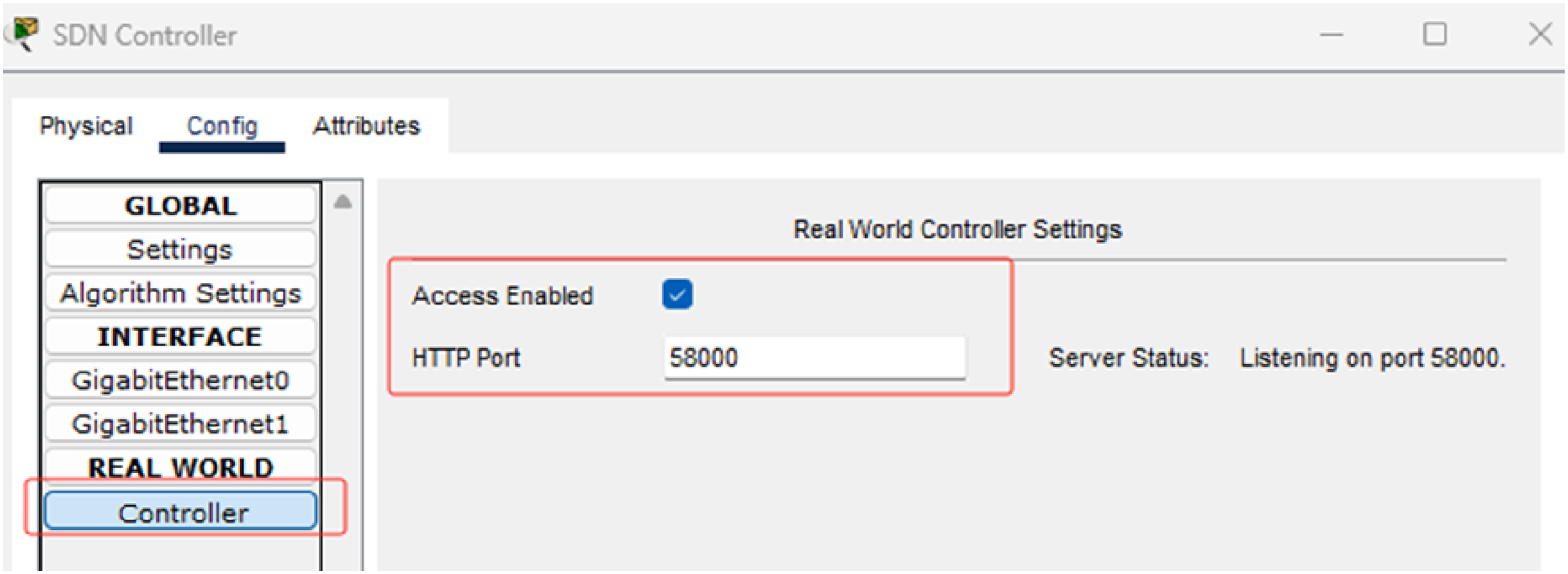
Open the browser of the host and enter https://127.0.0.1:58000. Enter the username and password to access the web page of the controller, and the user name and password must be registered for the first access (assuming that the user name and password are admin), as shown in Figure 7. Login controller.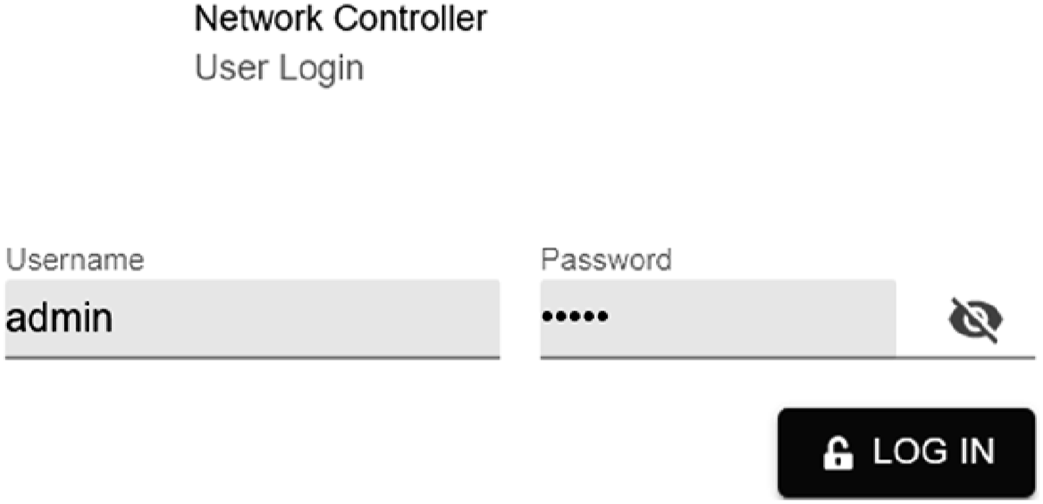
On the CREDENTIALS page, add CLI Credentials. In this project, the user name, password, and enable password of the switch, router, and other devices are admin, as shown in Figure 8. Adding credentials.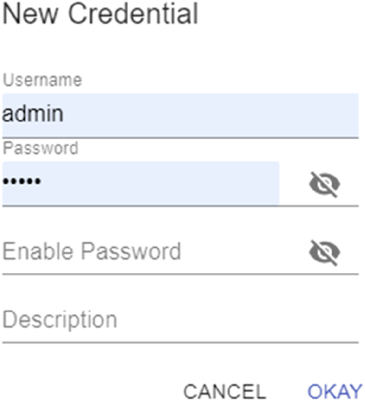
In the DISCOVERY page, add and edit the discovery conditions, select the default CDP for discovery type, the value of name is test, enter any IP for IP address list, keep the default values for timeout, Retry, CDP level, and specify the credentials admin, as shown in Figure 9. Add and edit discovery conditions.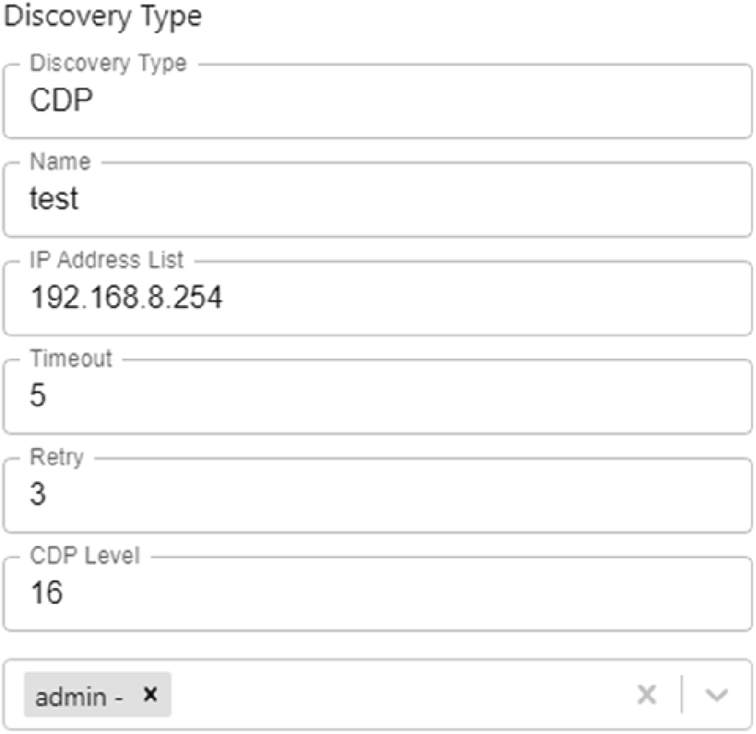
Project testing
Routing table test
On Router R1, execute “show ip route” to view the routing table, the output has 10.0.0.0/8, 192.168.8.0/24, 192.168.10.0/24, 192.168.20.0/24, and other direct routes, and all networks are displayed in the routing table.
Network connectivity test
Connectivity was tested by pinging any IPs of PC1, PC2, PC3, PC4, WLC, SDN controller, AP1, AP2, R1, S1, and S0, and the test results were all normal.
Provisioning test
On the DISCOVERY page, all devices for device name, type, IP, and reachability status are shown in Figure 10. Discovery all devices list.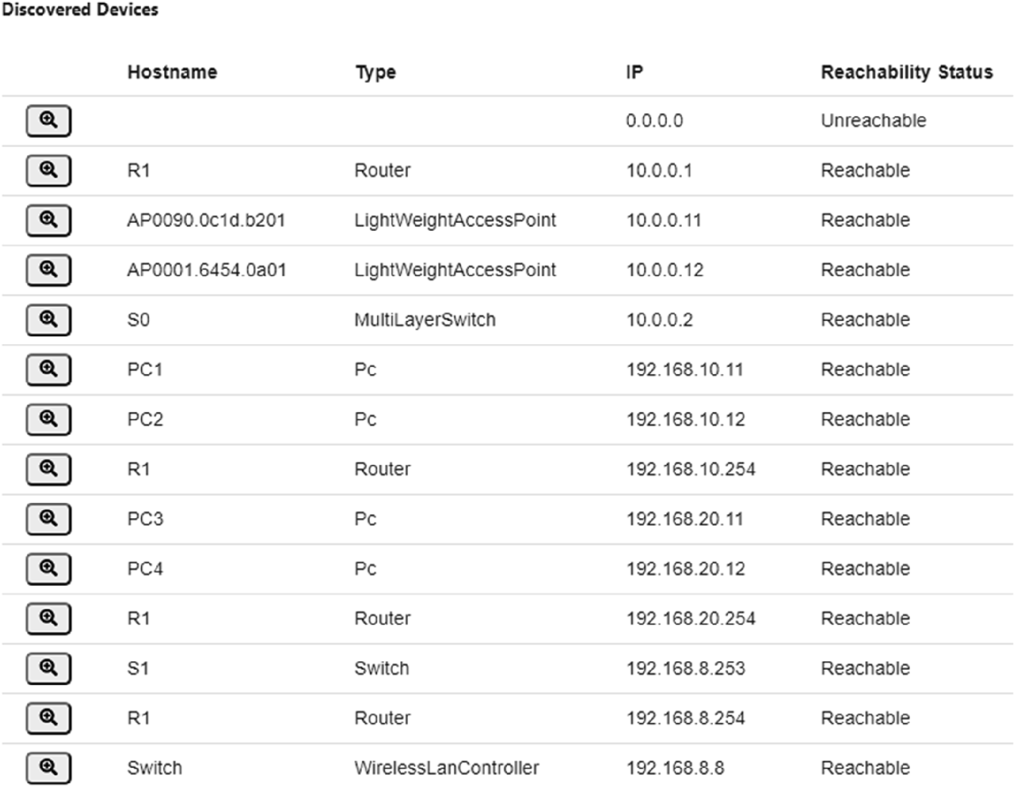
The status of the routers and switches is displayed on the NETWORK DEVICE page, as shown in Figure 11. List of discovery routers and switches.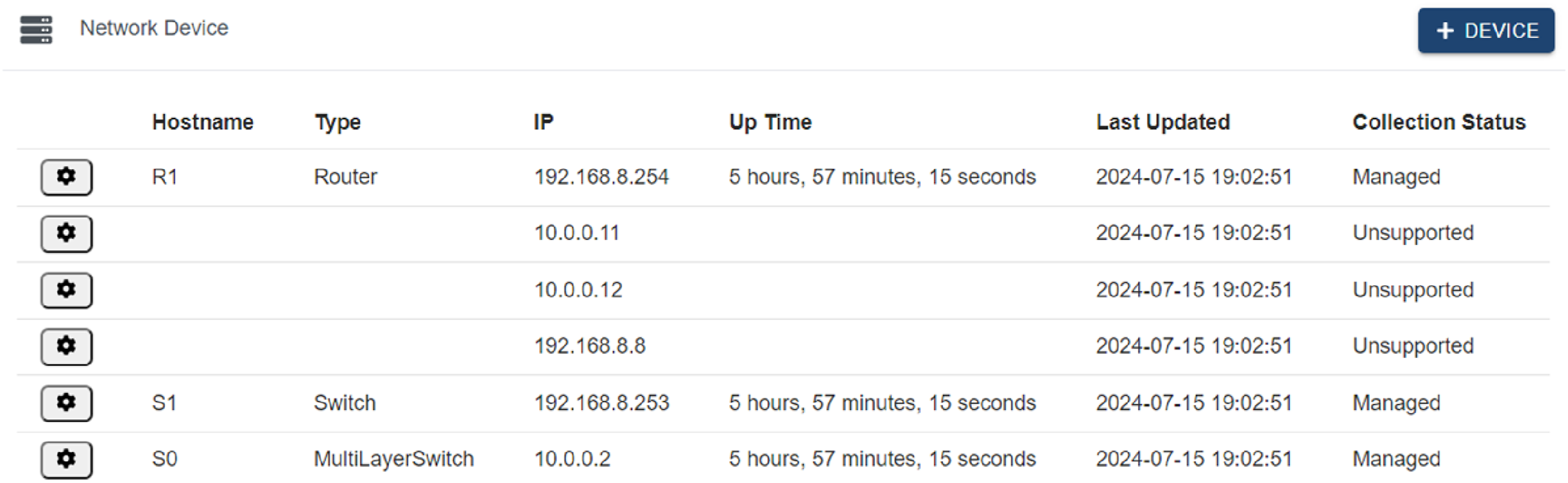
Assurance test
On the ASSURANCE page, the health status of all devices is displayed, showing the health percentage as a pie chart, as shown in Figure 12. Health status statistics for all devices.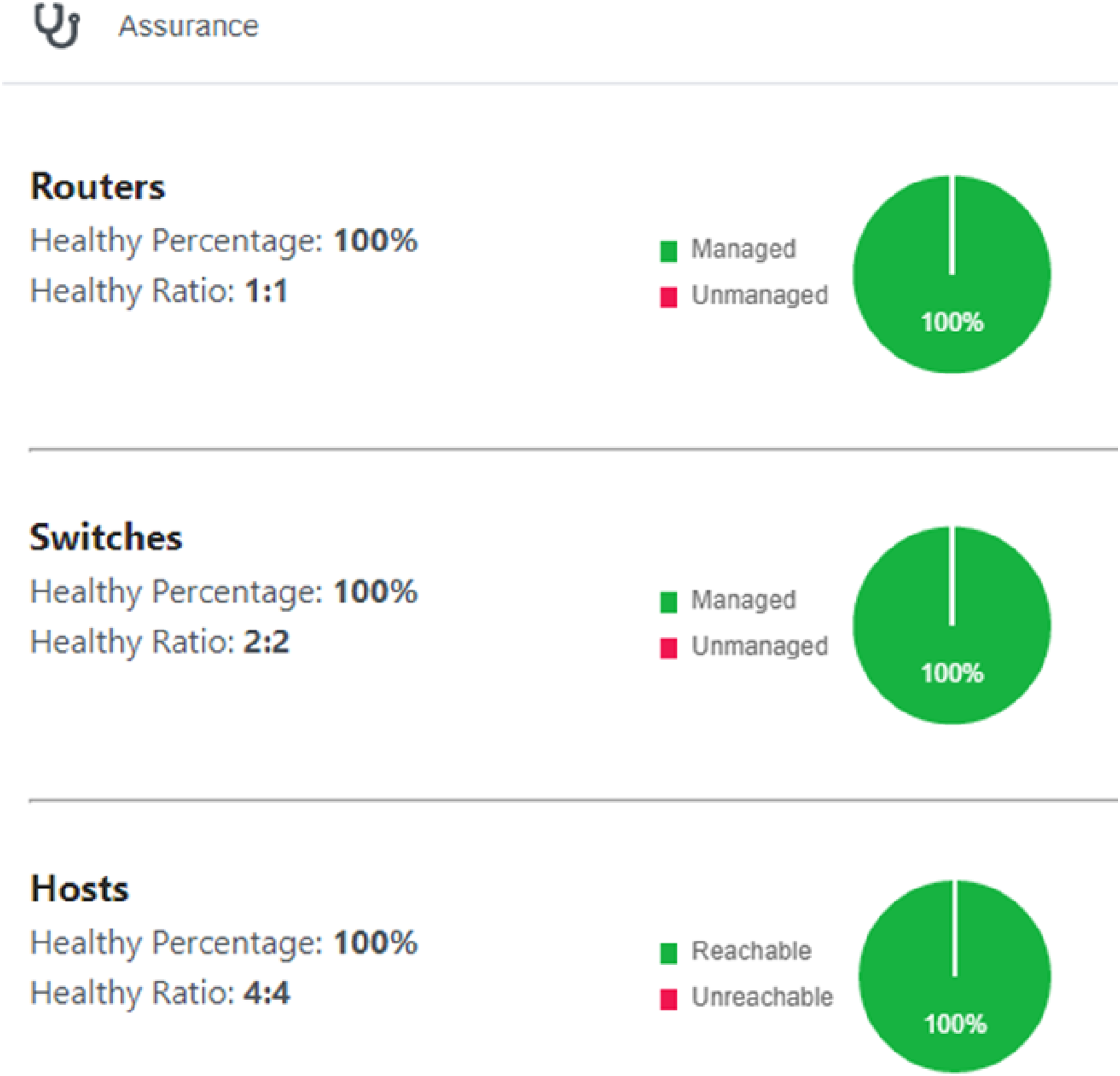
The health statuses of the routers, switches, and hosts are updated periodically (6 s), as shown in Figure 13. Periodic health status of all devices.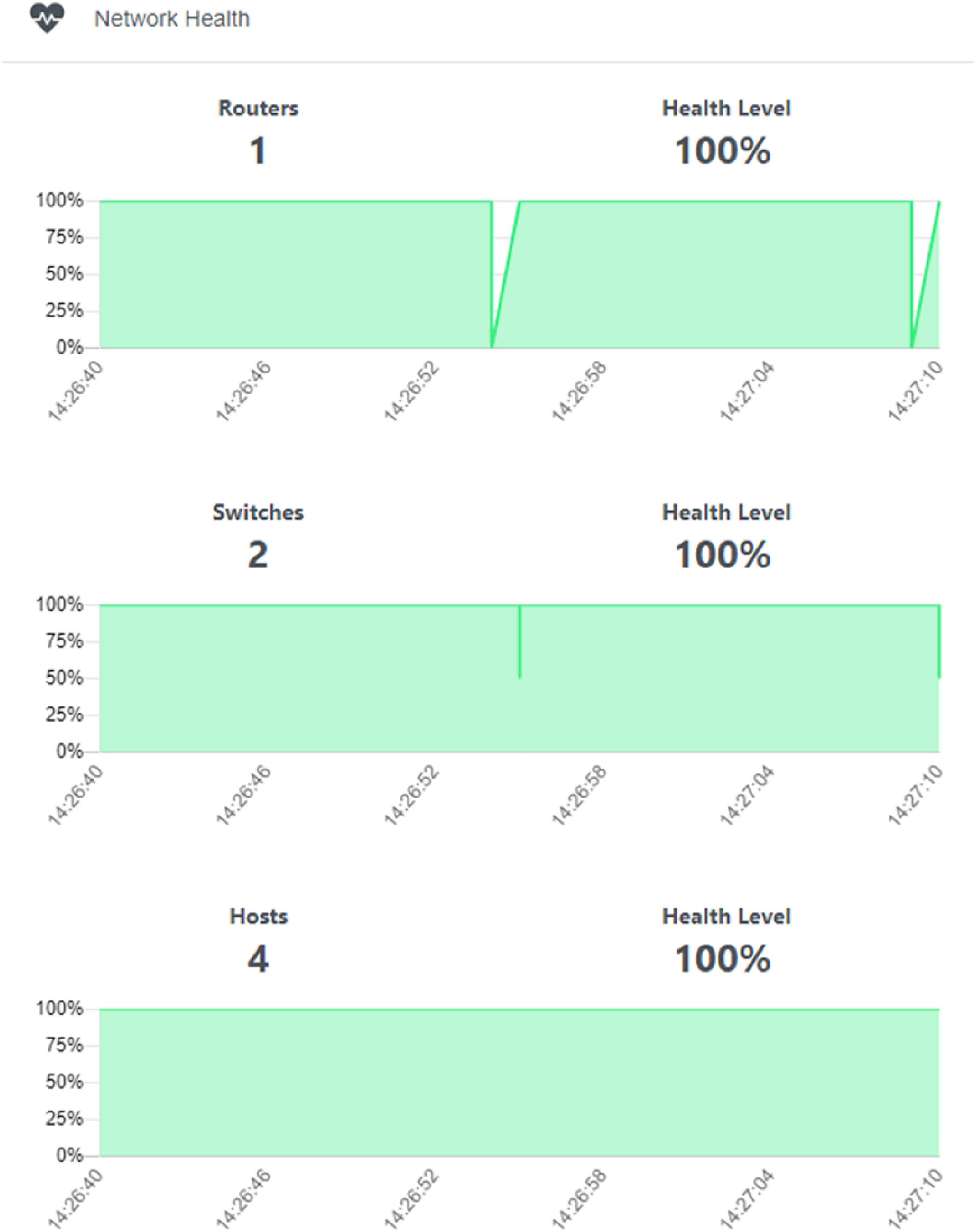
On the HOSTS page, the host and network devices (i.e., APs) to which it is connected are discovered, as shown in Figure 14. Discovery hosts and connected network devices.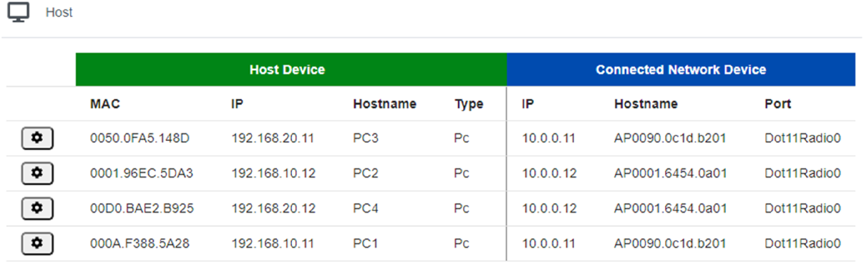
In the TOPOLOGY page, we test the auto-discovery topology function; only routers R1, S1, and S0 are shown, because the devices such as APs and hosts do not support SDN; they are not shown here.
On the PATH TRACE page, test the graphical path tracing function and test the connectivity from host PC1 to PC4 and PC1 to SDN Controller, respectively, as shown in Figure 15. Testing graphical path trace.
Dashboard test
The dashboard already displays this information, such as the percentage of hosts that can be reached via ping, percentage of network devices in the managed state, number of hosts and network devices, and state statistics, as shown in Figure 16. Dashboard test.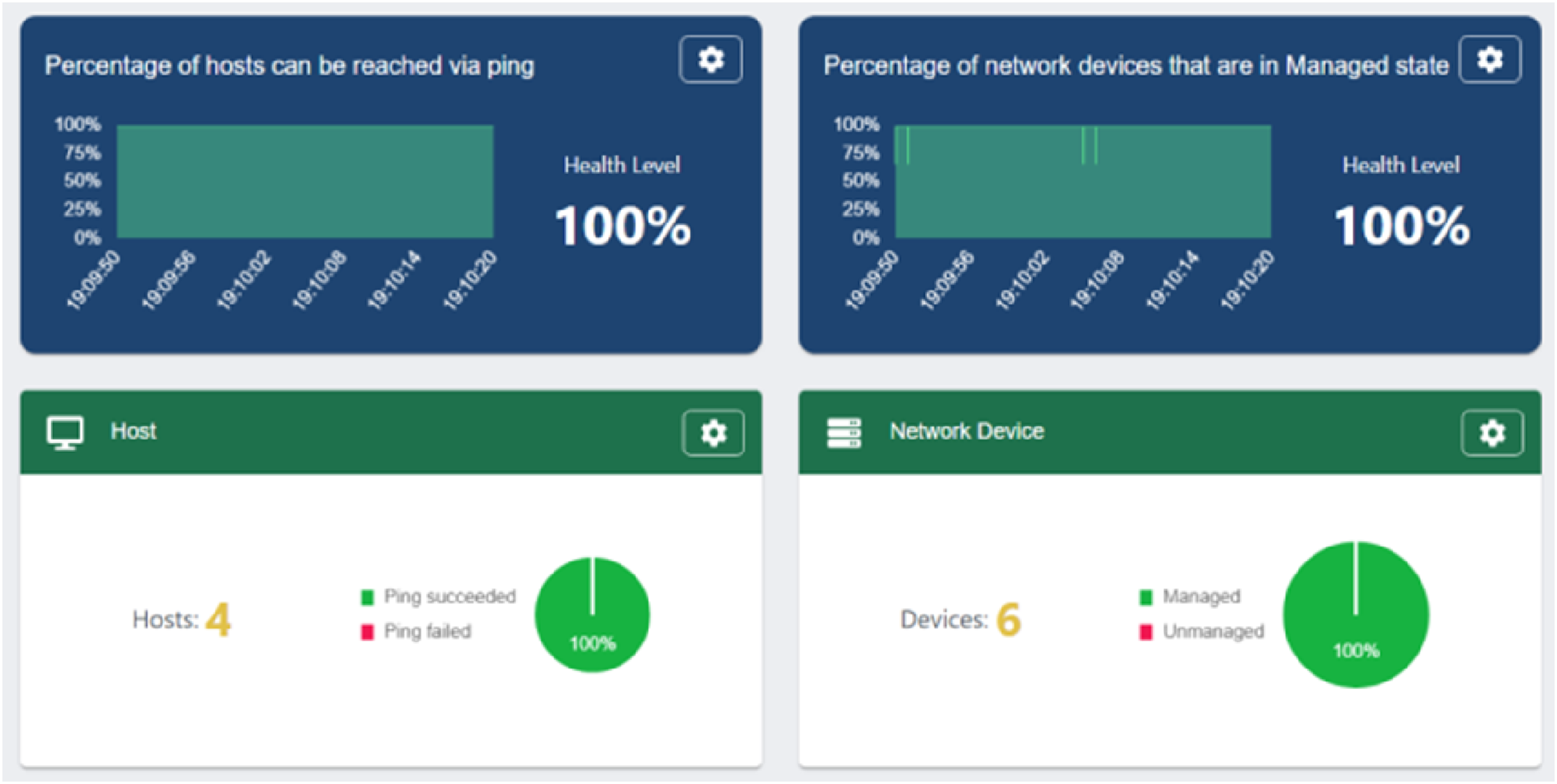
Conclusion
In order to provide campus wireless network access services with wider coverage, more convenient, more secure, and centrally manageable, this research integrates key technologies such as WLAN, SDN, network simulation, VLAN, and DHCP, and designs a new campus WLAN simulation project based on the dual-controller architecture of “software-defined network controller + wireless local area network controller,” and describes in detail the implementation of the project. After testing, the designed project operates stably, and both the wireless network and SDN controller operate normally. WLAN simulation based on SDN and WLC can not only improve the efficiency and flexibility of network management but also optimize the performance and security of wireless networks, which is an important technology for modern network management. This research is helpful to understand the working principle of WLAN and SDN and also helps to familiarize with the design and implementation process of WLAN and SDN, which provides a useful reference for network engineers and technicians. Of course, although this study has the above significance, there are some shortcomings, such as the simulation scenario lacks the support of real devices and actual campus network, and it cannot be directly applied to the actual campus network yet, and these shortcomings hope to have the opportunity to be improved in the future research.
Statements and declarations
Footnotes
Acknowledgments
The authors acknowledge the Research and Practice Program on Higher Education Teaching Reform in Henan Province (Graduate Education Category, 2023SJGLX159Y), Postgraduate Education Reform and Quality Improvement Project of Henan Province (Grant: YJS2023ZX08), Innovation Training Program for College Students in Henan Province (Grant: 542213320129), Specialized and Creative Integration Characteristic Demonstration Courses(Second Batch) in Henan Province (Comprehensive Practice of Computer Network Technology, Grant: 74), and Research Project on Smart Teaching in Ordinary Undergraduate Higher Education Institutions in Henan Province (Grant: 30).
Declaration of conflicting interests
The author(s) declared no potential conflicts of interest with respect to the research, authorship, and/or publication of this article.
Funding
The authors disclosed receipt of the following financial support for the research, authorship, and/or publication of this article: This work is supported by Research and Practice Program on Higher Education Teaching Reform in Henan Province (Graduate Education Category) (2023SJGLX159Y), Postgraduate Education Reform and Quality Improvement Project of Henan Province (YJS2023ZX08), Specialized and Creative Integration Characteristic Demonstration Courses (Second Batch) in Henan Province (Comprehensive Practice of Computer Network Technology) (74), Innovation Training Program for College Students in Henan Province (542213320129), and Research Project on Smart Teaching in Ordinary Undergraduate Higher Education Institutions in Henan Province (30).