




Abstract
The inspection of railway infrastructure faces significant challenges due to heterogeneous environmental conditions and non-uniform illumination patterns, leading to suboptimal detection performance in conventional robotic systems. This study develops a multi-stage image enhancement pipeline incorporating adaptive target segmentation and stereoscopic correspondence matching. A cross-sensor calibration protocol establishes precise spatial coordinates for defect localization through binocular disparity analysis. The proposed framework integrates an enhanced YOLOv5 architecture with context-aware attention modules, developing a hierarchical feature learning architecture that combines pyramidal representation with bidirectional multi-scale feature fusion layers. Experimental validation demonstrates 91.5% precision in fastener absence detection with optimized computational efficiency, indicating substantial improvements in automated rail defect diagnostics compared to baseline systems.
Introduction
In recent years, with the rapid development of rail transit, the safe operation and maintenance of railway and urban rail systems have faced increasingly severe challenges. Defects such as cracks, wear, and loose bolts in the track structure, as well as abnormal conditions of critical equipment such as contact lines and switches, can all lead to major safety accidents. 1 Traditional manual inspection methods rely on inspectors walking along track lines at regular intervals or using simple tools to conduct visual inspections, making it difficult to identify and locate defects comprehensively, promptly, and accurately. 2 In addition, manual inspections mostly rely on paper documents or basic electronic spreadsheets, lacking efficient information management methods, 3 and are unable to meet the refined and intelligent requirements of modern rail transit for safe operation and maintenance. Breakthroughs in deep learning and computer vision technologies have provided new solutions for rail inspection. 4 Deep learning-based image recognition algorithms can efficiently detect subtle defects on track surfaces, effectively overcoming the limitations of traditional manual inspections, significantly improving inspection efficiency and defect identification accuracy, 5 and providing strong technical support for the safe operation of rail transit systems.
The track inspection robot system is primarily designed to detect defects such as cracks, wear, and loose bolts in track structures. Hongbo et al. 6 located the fastener area based on grayscale and gradient features, extracted the track image harr features, and used the Adaboost algorithm 7 to judge and divide the fastener images, but the detection results were easily affected by lighting. Fan et al. 8 extracted HOG features from fastener images, trained a support vector machine (SVM) classifier to identify fastener images, and improved the detection rate, but this method requires high positioning accuracy for fastener images. Biswas et al. 9 extracted track images using Shi-Tomasi and Harris-Stephen fusion features, and classified and identified fasteners using an improved SVM, achieving a detection success rate of 81.25%. Manikandan et al. 10 combined local binary pattern features, grayscale co-occurrence matrix features, and discrete wavelet transform as image features, and used decision trees for fastener recognition and classification, but only for track crack detection. Han et al. 11 adopted a top-down approach, utilizing edge density maps and the RANSAC algorithm 12 to perform coarse localization of the fastener region, and then used support vector regression (SVR) to determine fastener missing, achieving a fastener detection success rate of 85.6%.
Deep learning-based track image detection methods can extract more generalized track image features, offering higher algorithm robustness and detection accuracy. The first type is a second-order detection network for target localization and classification. This type of network first generates a series of candidate regions as detection target samples and feature information, and then predicts the localization information and region classification of the targets. 13 Chen et al. 14 used a material classification and semantic segmentation algorithm based on deep convolutional neural networks (CNN) to achieve a material classification accuracy of 93.35%. Due to the limited number of defective samples in track images, Gibert 15 applied multiple detectors such as SVM and CNN in a multi-task learning framework to improve detection accuracy. Compared with traditional feature analysis techniques, this approach achieved better generalization detection performance and improved detection efficiency. Wei et al. 16 used the Fast R-CNN method to identify and detect defects in track images, but the detection error was relatively high. Aydin et al. 17 utilized CNN and restricted Boltzmann machines 18 to extract edge features and texture features from track fastener images, then performed feature fusion, and finally detected defects using the Mahalanobis distance similarity measurement method, achieving a fastener defect detection rate of 85.06%.
The second type integrates target detection and localization into a unified detection network. This type of network generally does not require the generation of candidate regions, but instead converts the detection targets into regression problems for processing, and directly predicts the detection target bounding boxes and category information through the network. Guo et al. 19 proposed a track image detection method based on the Transformer architecture, which achieved crack detection accuracy of 86.93% through an encoder and decoder structure. Brintha et al. 20 trained YOLO as a deep learning model using the Darknet-53 prediction structure to improve the network’s classification and recognition capabilities, achieving an average detection success rate of 87.08%. Cai et al. 21 used a residual CNN structure and introduced visual image color mixing enhancement technology to improve detection speed.
In summary, under complex and changing track conditions and unstable lighting conditions, the current intelligent level of track inspection robot systems is insufficient and has inadequate environmental sensing and adaptation, making it difficult to efficiently complete the task of detecting track structural defects. In response to the above issues, this paper proposes an optimization method for track inspection robot systems based on deep learning and image processing, and conducts performance analysis experiments. First, this paper selects the threshold for image segmentation and uses discriminant analysis to determine the optimal threshold. Through binarization processing, the background information of the image is removed to make the target information more prominent. After obtaining the optimal segmentation threshold, compare the gray values of all pixels with this value to reassign the gray values of the pixels, ultimately obtaining a high-quality track structure image. Subsequently, binocular vision calibration was performed on the camera, and the depth of the corresponding points was calculated to obtain the three-dimensional spatial information of the defective parts on the track, thereby determining the specific location of the track defects. Based on this, this paper designed a track defect image detection model based on an improved YOLOv5 model and attention mechanism. This model uses an improved FPN structure combined with an attention mechanism as the backbone network, an improved FPN combined with a path aggregation network as the neck structure, and a YOLO decoupled dual-path detection head for detection. The main network, neck structure, and detection head convolution modules of this model have all been designed to be lightweight. Finally, performance analysis experiments were conducted. The comparison experiments showed that the proposed method achieved a detection accuracy of over 90% for track fastener defects, outperforming the comparison methods. Additionally, ablation experiments confirmed the effectiveness of all components in the model.
Methods and materials
Overview of the rail inspection robot inspection system
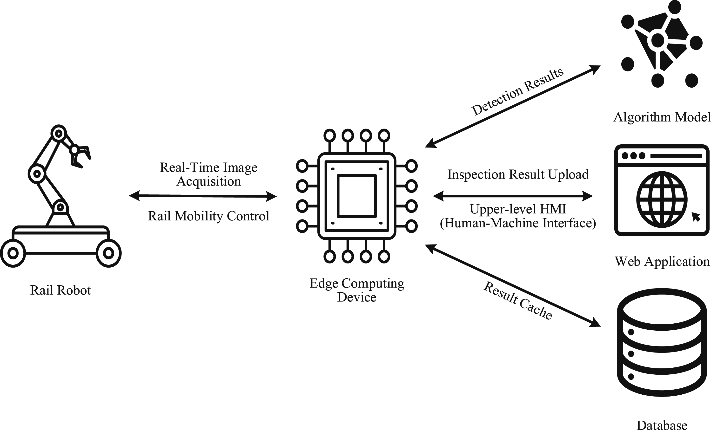
The rail inspection robot system is an intelligent detection platform that integrates mechanical automation, sensor technology, computer vision, and artificial intelligence algorithms. The existing deep learning-based track inspection robot system can automatically extract features and accurately identify potential risks such as track surface defects and foreign object intrusion compared to traditional manual inspection methods. By collecting a large amount of inspection data, deep learning is utilized for trend analysis and predictive maintenance. The system mainly consists of edge computing devices, algorithm models, databases, and web applications,
22
as shown in Figure 1. (1) Edge computing devices. These are computer systems that provide data communication services and various detection algorithms locally.
23
During inspections, they perform image recognition and corresponding logical operations, and transmit the inspection results via the enterprise local area network for data transmission. (2) An intelligent algorithm used for image recognition of sampled images during patrol inspections, mainly used for knob switch status detection, track structure damage detection, and other functions.
24
(3) Web application. Presents daily inspection data and results to users in a visual manner, and provides interactive features such as viewing inspection progress and querying historical inspection results. (4) Database. Used to store and manage data, save the results of each inspection and the sample images that generated error identifications, for later data tracing and model iteration updates. Orbital inspection robot system architecture.
Convolutional neural network
CNN is a deep learning model specifically designed to process data with a grid structure (such as images, videos, and speech).
25
Traditional neural networks use a fully connected architecture, whereas CNN neurons are only linked to local regions of the input data, thereby reducing parameters’ number and capturing spatial local features. Neurons in the convolutional layer in a CNN are connected only to localized regions (i.e., local receptive fields) of the input data, rather than to the entire input data. This localized connectivity reduces the number of parameters in the network, and weight sharing makes the network robust to the recognition of similar features at different locations. In contrast, traditional neural networks usually use a fully connected approach, where each neuron is connected to all the neurons in the previous layer, with a large number of parameters, which can easily lead to overfitting, especially when dealing with high-dimensional data. CNNs mainly consist of convolution levels, pooling levels, and fully connected levels,
26
as shown below. (1) Convolution level. By introducing local receptive fields and weight sharing,
27
the number of parameters required for feature extraction has been significantly reduced. If the input of the convolution level is an N-dimensional feature map, the output features are calculated as follows. (2) Pooling level. By reducing the size of network features, redundant image features are eliminated based on various image downsampling rules. The output features corresponding to the pooling layer are as follows, where (3) Fully connected level. This level has the characteristics of feature integration and dimension transformation, and can eliminate redundant information features to the greatest extent possible, retaining only the required target information. The fully connected level is calculated as follows.



Rail image preprocessing and spatial location acquisition of defects
Track image preprocessing
To achieve precise detection of defects in rail-related components, this paper first implements preprocessing such as target segmentation and binocular target matching
28
on the collected images, effectively extracting and enhancing the useful information in the images, so as to obtain the three-dimensional information of the spatial position of the track defect fasteners by performing binocular vision calibration on the camera and calculating the depth of the points with the same name, thus laying the groundwork for the subsequent detection of defective track structures. Track structure image preprocessing flow is shown in Figure 2. Track structure image preprocessing flow.
Before performing binarization on the collected orbital environment images, select the image segmentation threshold. Selecting a threshold that is too large will result in the loss of necessary information, while selecting a threshold that is too small will result in the extraction of unnecessary information. Use discriminant analysis to determine the optimal threshold. The specific steps are as follows. (1) Analyze the corresponding gray distribution information of all pixels in the image. Let m represent the total number of pixels in the image, and (2) Calculate the interclass variance values based on the 0-th-order moment gray distribution and the 1-st order moment gray distribution of gray level l. When the interclass variance reaches its maximum value, the corresponding l value is the optimal segmentation point, that is, the optimal threshold, as shown below.



By applying binarization processing,
30
background information in the image can be removed, making the target information more prominent. After obtaining the optimal segmentation threshold, the grayscale values of all pixels are compared with this value, and the grayscale values of the pixels are reassigned accordingly. Finally, the entire image is redrawn. The assignment rules are as follows.

Obtaining the spatial location of track structural defects
In the preprocessed images mentioned above, obtain the spatial positions of the track defect components. Through image segmentation and dual-object matching operations in image preprocessing, useful information in the images can be effectively extracted and enhanced to obtain the spatial positions of track defects more accurately. By implementing binocular vision calibration on the camera and introducing the calculation of depth of homonymous points, the three-dimensional spatial information of the track defect parts is obtained. In the depth calculation of the same-named point, 31 first set the upper left corner of the image as the origin. The horizontal extension to the right from this point is the positive direction of the X-axis, and the vertical extension downward is the positive direction of the Y-axis. At this point, every pixel in the image has a unique coordinate, and the target point also has coordinates.
The first step in the calculation is to obtain the coordinates of points with the same name in the image, denoted by


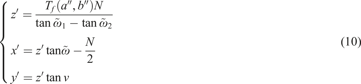
Based on the triangular relationship formed by two pixel points and physical points, the preprocessed image information is input into the system to obtain the final relative coordinates of the target point, as shown below, where N is the distance between the two cameras,
Optimization of a rail inspection robot system based on deep learning and image processing
Optimized model design for rail inspection robot system
Under complex track conditions and uneven lighting, existing track inspection robot systems are unable to meet intelligent inspection requirements, resulting in low efficiency in detecting track structural defects. To this end, after locating the spatial position of the track defect, we propose a detection and recognition method for track inspection robots based on improved YOLOv5
32
and attention mechanism to improve the accuracy of existing inspection robot systems in detecting track structural defects. The overall model is shown in Figure 3. Orbital inspection robot inspection model.
First, a feature extraction network based on improved FPN 33 and attention mechanism was constructed to fuse different levels of features extracted by traditional methods. The traditional FPN is unidirectional, that is, transferring information from the high-level feature map to the low-level feature map, the feature fusion method is relatively single, and the information circulation is not sufficient, which leads to insufficient and efficient fusion between features of different scales, and restricts the model’s ability to detect multi-scale targets. Therefore, in this paper, the convolution module in FPN is designed to be lightweight so that the detection ability of the model can be improved. Combined with the attention mechanism, the data collected by the track inspection robot was processed to extract image features, further enhancing the feature extraction function. Finally, an improved YOLOv5 model was used to build a track structure defect detection model for track inspection robots. Therefore, the Neck part adopts an improved FPN combined with a path aggregation network design to improve detection speed and accuracy.
Rail image feature extraction based on improved feature pyramid network and attention mechanism
Since traditional FPN uses multiple convolution modules for feature extraction, it consumes a large amount of computing resources. To address this issue, the convolution modules of FPN were designed to be lightweight, using a reverse residual structure as the convolution module. First, use

In the inverse residual structure, dimensionality increase transformation utilizes point convolution operations to fuse low-dimensional channel information and achieve channel dimensionality increase. Feature extraction transformation utilizes

To ensure that low-cost dimensionality extension can effectively replace the standard reverse residual structure’s dimensionality changes. To address this issue, one feature extraction branch was added to the lightweight reverse residual structure. This branch contains part of the output results from the point convolution operation. The lightweight reverse residual structure is shown in equation (13).

For the goal of enhancing the expression of image features, SAM is used to enhance the output results of FPN. The FPN output enhancement module is divided into layer attention (LAM) units, spatial attention (SPAM) units, and channel attention (CAM) units. LAM is used to distinguish shallow features, middle features, and deep features in fusion features. The operation process is as follows.

LAM first performs pooling on the output results of the feature fusion module, then uses
The SPAM unit is used to distinguish the spatial locations of different features in images. The output results of LAM need to be first processed by average pooling and maximum pooling. After the pooling operation, the processed results are merged and dimension reduced using, and then used to generate SPAM features, as shown in equation (15).

The SPAM output features first undergo average pooling, then are processed by a fully connected layer to further fuse all features, and finally, the CAM features are obtained using the function, as shown below.

Rail structure defect detection based on improved YOLOv5
The general structure of the detection algorithm based on YOLOv5 is divided into three parts: Backbone, Neck, and Head.
34
Among them, Backbone is the lightweight feature extraction module designed in the previous section. Therefore, the Neck part also adopts the design of improved FPN combined with path aggregation network to achieve the lightweight detection model, as shown in Figure 4. In the Neck structure, the Detection Block is replaced with a lightweight convolution module designed for this purpose. The lightweight Neck structure employs cross-stage connections to further reduce the computational load when reducing feature channels’ number. Improved YOLOv5 model.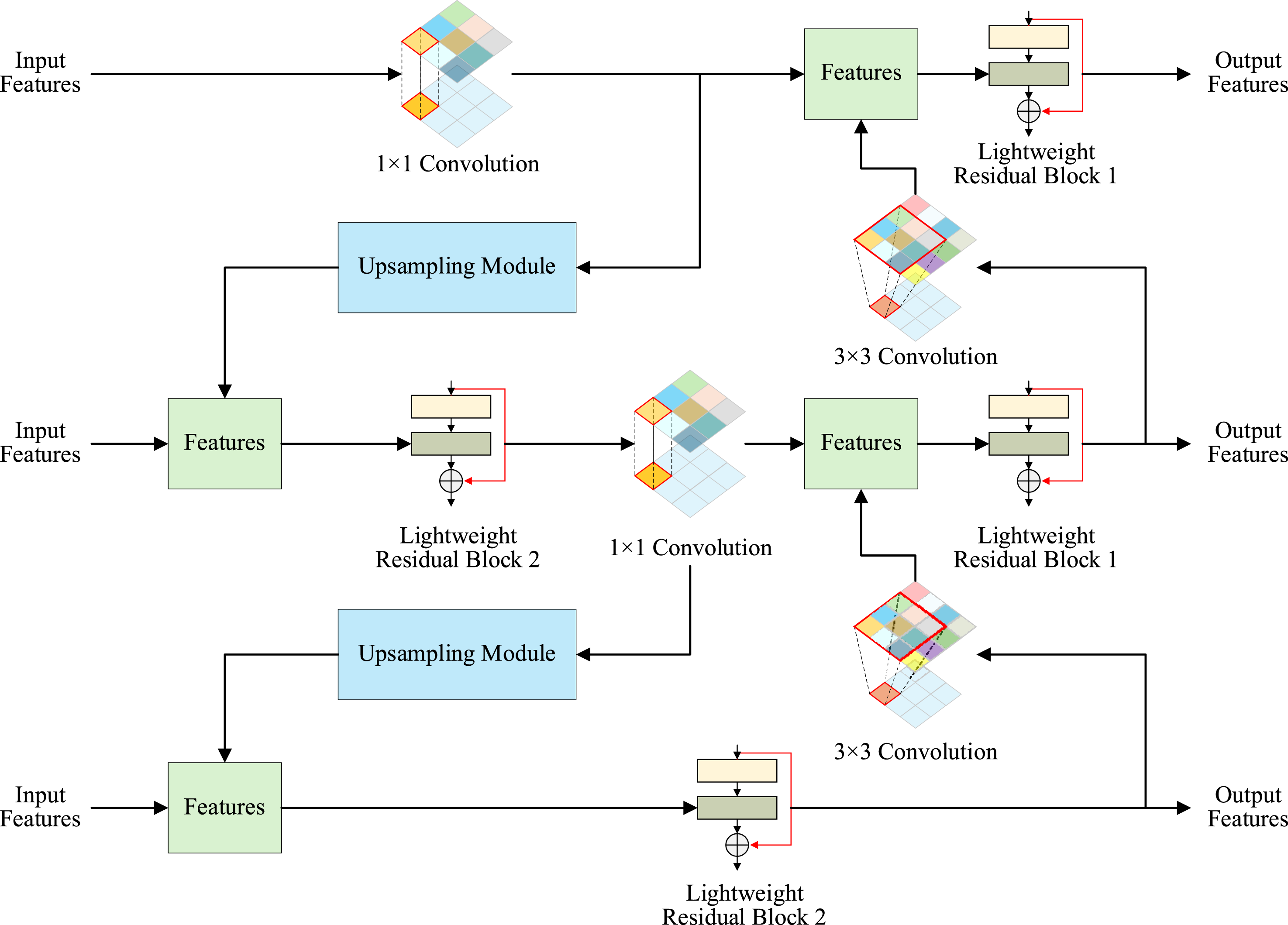
In the improved YOLOv5 Head structure, there are two paths: one path is responsible for feature classification tasks, and the other path is responsible for feature localization tasks. When assigning labels in the result output, the similarity-based optimal transport allocation (SimOTA) algorithm
35
is used to adapt to different target requirements by dynamically allocating the number of positive samples, thereby improving target detection performance. When designing the model loss function, three loss functions were designed: confidence loss, prediction box regression loss, and classification loss. (1) Confidence loss. Focal Loss
36
is used to address the class imbalance problem by reducing the weight of easily classified samples, thereby enabling the model to focus on hard-to-classify samples, as shown below. (2) Prediction box regression loss. An efficient intersection-over-union loss function is used, which is an improvement on the traditional intersection-over-union loss function, taking into account the overlapping area, center point distance, and similarity of the width-to-height ratio, as shown below. (3) Classification loss. Binary cross-entropy loss is used to measure the difference between the probability distribution of the model’s predictions and the probability distribution of the true labels.
37
Therefore, this loss function is used as the classification loss for the target detection model, as shown in equation (19), where




Experimental results and analyses
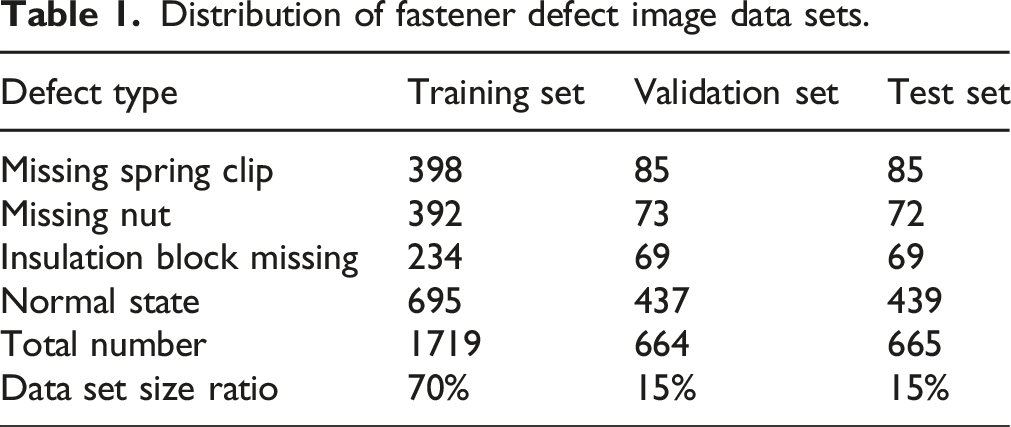
Distribution of fastener defect image data sets.
This experiment uses the Linux operating system Ubuntu 18.04. The hardware configuration includes an Intel i7-8700K processor and an NVIDIA GTX 2080 Super graphics card. The system is installed with CUDA 10.1, and OpenCV 3.4.9, and the graphics card can accelerate model training and use. The software uses TensorFlow, a Python-based framework, for model development. The experiment was conducted with 50 iterations, using the Adam optimizer and a learning rate of 0.01.
For the sake of analysis, this paper selects CNN-RBM [17], TransAE [19], and FOD-YOLO [20] as comparison methods. The confusion matrices of the detection results of the four types of track fastener missing using different methods are shown in Figure 5. As shown in Figure 5, CNN-RBM has the lowest detection accuracy, with detection accuracy for all types of track fastener defects below 85%. The detection accuracy of TransAE and FOD-YOLO is above 85%, but neither exceeds 90%. The proposed DLIP method achieves the highest detection accuracy for detecting missing insulation blocks on rail fasteners, reaching 92.8%, and a detection accuracy of 90.8% for detecting normal rail conditions. Overall, the DLIP method achieves detection accuracy above 90% for detecting defects in rail fasteners, demonstrating high detection accuracy. Improved YOLOv5 model.
The precision-recall (PR) curves and AUC values for different methods are shown in Figure 6. In the evaluation metrics, precision is negatively correlated with recall, which is positively correlated with positive samples, while precision is positively correlated with negative samples. The PR curve directly shows the specific detection accuracy and overall average detection accuracy. As can be seen from the figure, the area enclosed by DLIP and the coordinate axes is greater than that of the baseline method, indicating that DLIP has better overall detection performance than the comparison method. In addition, the AUC values of CNN-RBM, TransAE, FOD-YOLO, and DLIP were 0.866, 0.903, 0.950, and 0.963, respectively, with DLIP having the highest AUC value, indicating its superior detection performance. PR curves for different methods.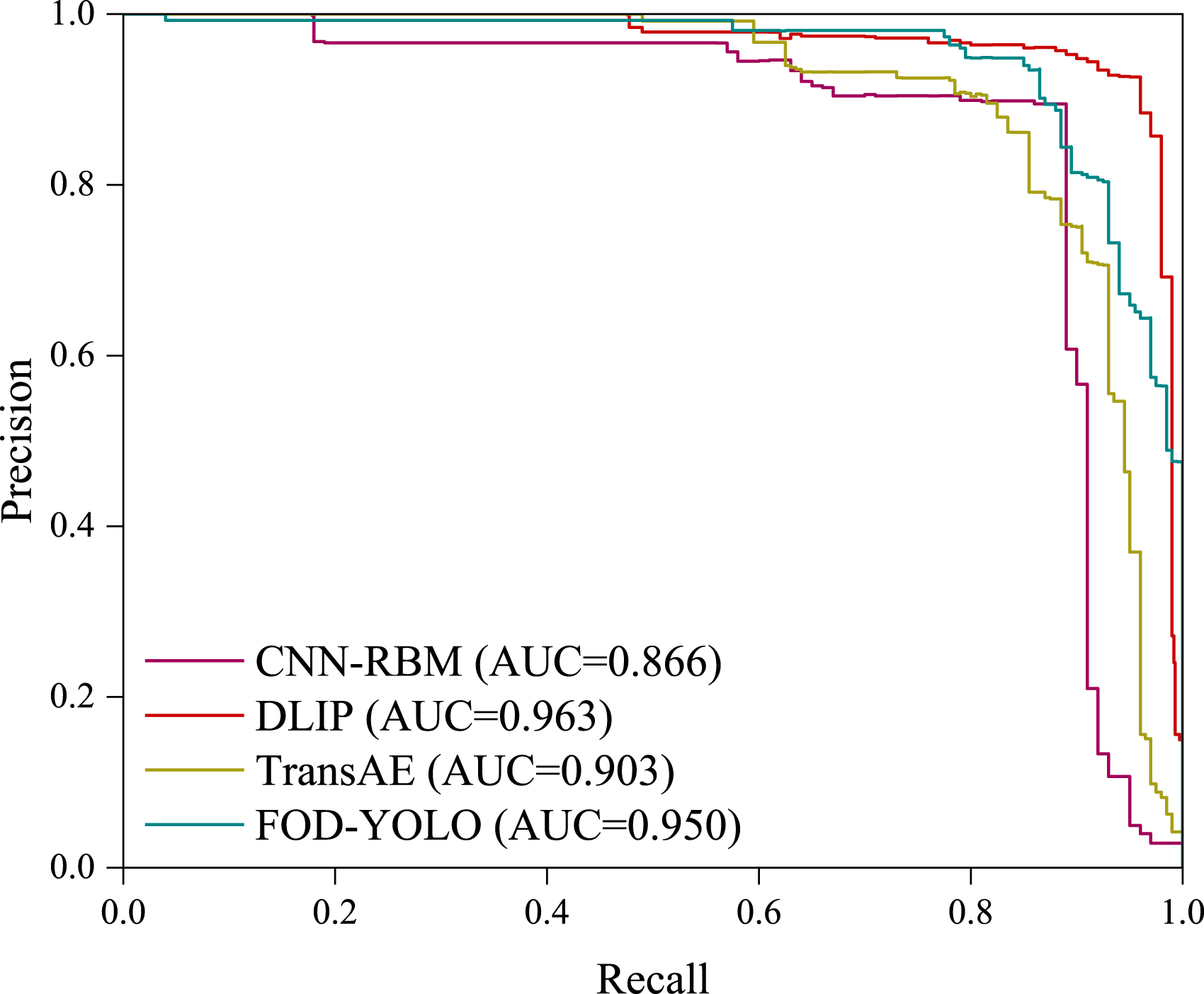
Ablation results.
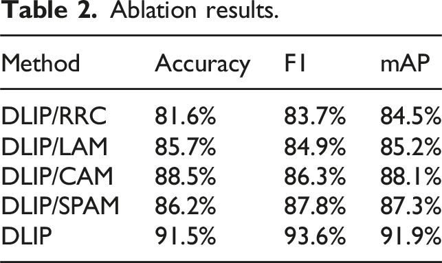
The detection accuracy of DLIP/RRC is the lowest, at only 81.6%, indicating that the introduction of reverse residual structure can significantly improve the performance of the detection method. The detection accuracy of DLIP/LAM, DLIP/CAM, and DLIP/SPAM is similar, indicating that removing any of the attention mechanisms in the proposed method has a significant impact on the performance of the detection method. DLIP has the highest detection accuracy rate of 91.5%, indicating that DLIP, which integrates all components, has the best detection performance. When comparing the detection accuracy metric mAP, DLIP achieved the mAP of 91.9%, representing improvements of 7.4%, 6.7%, 3.8%, and 4.6% compared to DLIP/RRC, DLIP/LAM, DLIP/CAM, and DLIP/SPAM, respectively. This demonstrates that all components in DLIP have a decisive impact on detection performance.
Conclusion
Under harsh working conditions such as complex and changing track environments and uneven lighting conditions, the intelligent inspection capabilities of existing track inspection robot systems face significant challenges, directly resulting in track structure defect detection efficiency that is unable to meet actual needs. To address the above issues, we propose an optimization method for track inspection robot systems based on deep learning and image processing, and conduct performance analysis experiments. This paper first selects the threshold for segmenting the original track image, using discriminant analysis to determine the optimal threshold. Through binarization processing, the background information of the image is removed, and the grayscale values of all pixels are compared with this value, thereby reassigning the grayscale values of the pixels and ultimately obtaining a high-quality track structure image. By implementing binocular vision calibration on the camera, we introduce the calculation of depth of homologous points to obtain three-dimensional information on the spatial location of track defects. On this basis, we optimize FPN based on a reverse residual structure to improve the backbone part of the improved YOLOv5 model as a lightweight feature extraction network that integrates FPN and attention mechanisms. Therefore, the Neck part adopts an improved FPN combined with a path aggregation network design to improve detection speed and accuracy. Performance analysis experiments show that the AUC value of the proposed method is 0.963, which can improve the accuracy and efficiency of track defect detection in complex environments.
Footnotes

Funding
The authors disclosed receipt of the following financial support for the research, authorship, and/or publication of this article: This research received financial assistance from the research and development service contract of unmanned intelligent inspection system for offshore wind farm booster station and metering station of Huaneng Jiaxing No. 2 offshore wind power project [HN-52CO-202200035-FWQT00015].
Declaration of conflicting interests
The authors declared no potential conflicts of interest with respect to the research, authorship, and/or publication of this article.