
Abstract
Pipelines serve as a crucial means for transporting hydrocarbon fluids across vast distances worldwide. These pipeline structures are meticulously designed to withstand various environmental loads, thereby ensuring the secure and dependable distribution of fluids from production points to distribution depots or coastal areas. However, the occurrence of leaks within pipeline networks poses a significant challenge, leading to substantial losses for pipeline operators and the environment. Pipeline failures can lead to serious ecological disasters, loss of life and economic setbacks. To mitigate these risks and maintain the safety and reliability of pipeline facilities, a significant amount of research has been devoted to implementing leakage detection and location systems employing diverse approaches. Based on the influence of corrosion and leakage on pipeline circumferential strain, this paper proposes a method to detect corrosion and leakage by using Optical Fiber Strain Sensor (OFSS) to monitor pipeline circumferential strain. The experimental results are verified. It provides a new idea and method for pipeline health monitoring.
Introduction
The use of pipelines plays an important role in the transportation of vital petroleum products, which make a significant contribution to a country’s economy. It has been proved that pipelines are the most economical and safest means for the transportation of oil and gas, meeting high requirements for efficiency and reliability. 1 For instance, the statistical data reveals that the use of trucks, ships, and railways to transport petroleum products has significantly higher fatalities per ton per mile compared to pipeline transport. 2 Nevertheless, with the increasing popularity of transporting hazardous substances through extensive pipeline networks worldwide in recent years, the risk of major accidents resulting from pipeline leakage or corrosion has also escalated. 3 These accidents can be attributed to pipeline leakages, corrosions, and equipment failures, 4 resulting in pipeline disruption or leakages, such as massive economic losses and serious pollution, especially if the leakages are not detected in time. 5 Incidents of pipeline leakages result in substantial economic losses, as evidenced by extensive research. The causes of pipeline damage are diverse and encompass various factors. Major contributors to pipeline failures include corrosion, third party damage, substandard pipeline quality, or improper pipeline installation. 6
In order to reduce the social impact of accidents such as leakages, it is essential to monitor the health of pipeline, detect leakages in time, and even predict leakages because early detection of leakages will allow for rapid response. As a result, it can reduce loss rates, injuries, and other serious consequences which caused by pipeline failures.
Based on different principles, several methods of pipeline leakage detection have been proposed in the past few decades. These methods include acoustic emission,7–9 FBG sensor,10–12 ground penetrating radar,13,14 negative pressure wave, 15 pressure point analysis,16–18 dynamic modeling, 19 steam sampling, infrared thermal imaging, signal processing, and mass-flow balance.20–22 Most of the above studies focus on pipeline leakage, and few focus on pipeline corrosion. In this study, a pipeline health monitoring method based on Optical Fiber Strain Sensor (OFSS) is proposed. This method uses OFSS to monitor the circumferential strain of pipelines, so as to detect corrosion and leakage.
Circumferential strain measurement theory
As shown in Figure 1, the pipeline will expand due to the pressure of the fluid in the pipeline during normal operation, and the normal tension generated at any section along the pipeline axis is defined as F
N
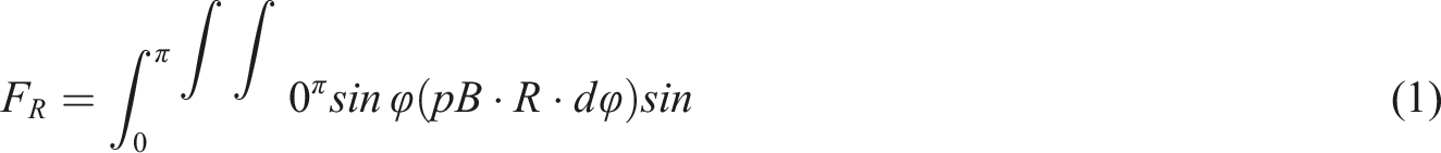
. By analyzing a semicircular truncated tube with length B, the resultant y-direction force F
R
caused by internal pressure p can be obtained by integrating (a) Pipeline diagram under internal pressure and (b) stress analysis of semi-circle.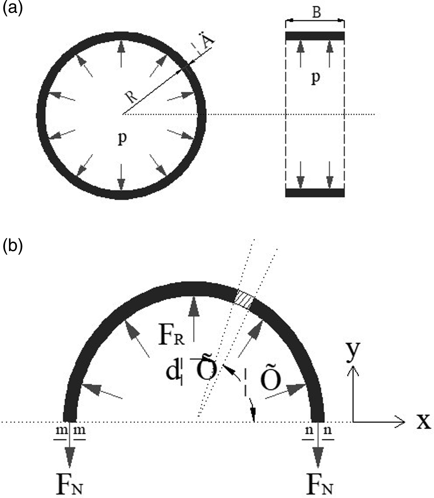
Because the pipeline thickness δ is much less than the radius R, it can be considered that the normal stress at any point on the sections m-m and n-n is equal. According to the force balance in the y direction, we can get:

Based on material mechanics theory, the circumferential stress and strain of the pipeline can be deduced:


Optical Fiber Strain Sensor (OFSS)
Principle of OFSS
When light propagates in an optical fiber, any changes in the external environment along the entire length or a portion of the fiber will result in corresponding changes in optical transmission characteristics. An optical fiber sensor is a device that detects these environmental changes by monitoring light transmission characteristics. Optical fiber gratings, specifically fiber Bragg gratings (FBGs), are periodic structures with varying refractive indices within the core region. These gratings are commonly used in communication systems and are created using ultraviolet holographic exposure methods with cesium-doped optical fibers that exhibit nonlinear absorption effects. The unique characteristic of these gratings is their ability to allow ordinary light to pass through unaffected while reflecting only specific wavelengths at the grating interface. The spacing between grating elements can be altered due to external stress, resulting in a change in wavelength for reflected light passing through them. Therefore, by monitoring this wavelength shift, it becomes possible to detect variations in strain within the external environment surrounding the grating. The OFSS utilized in this study belongs to this category and its principle is illustrated in Figure 2. Schematic of FBG.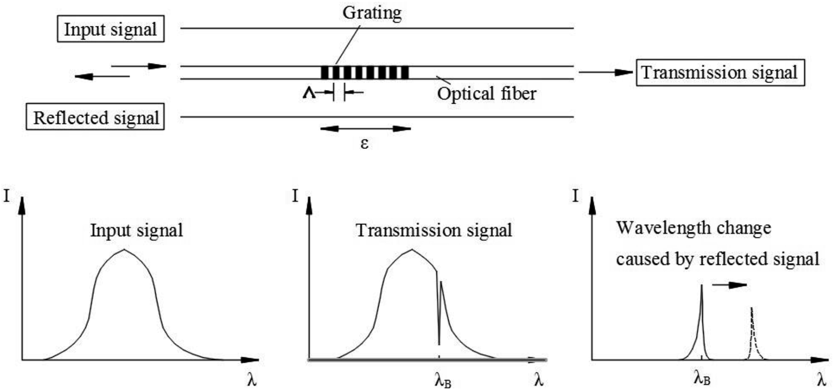
According to the sensing principle of fiber grating, the light with a wavelength of in the light beam will be reflected by the fiber grating. And

Figure 3 is the principle structure diagram of OFSS. First, a wide spectral light source is used to generate light with a certain bandwidth, which is incident on the fiber grating through the circulator. Since the fiber grating has the characteristic of selecting light with a specific wavelength, a specific wavelength of light will be reflected back, and its specific wavelength can be measured by the circulator and the demodulation device. When the external stress of the fiber grating changes, the wavelength of the reflected light will change, and the demodulation device can inversely determine the external strain by monitoring the wavelength change. Structure diagram of OFSS.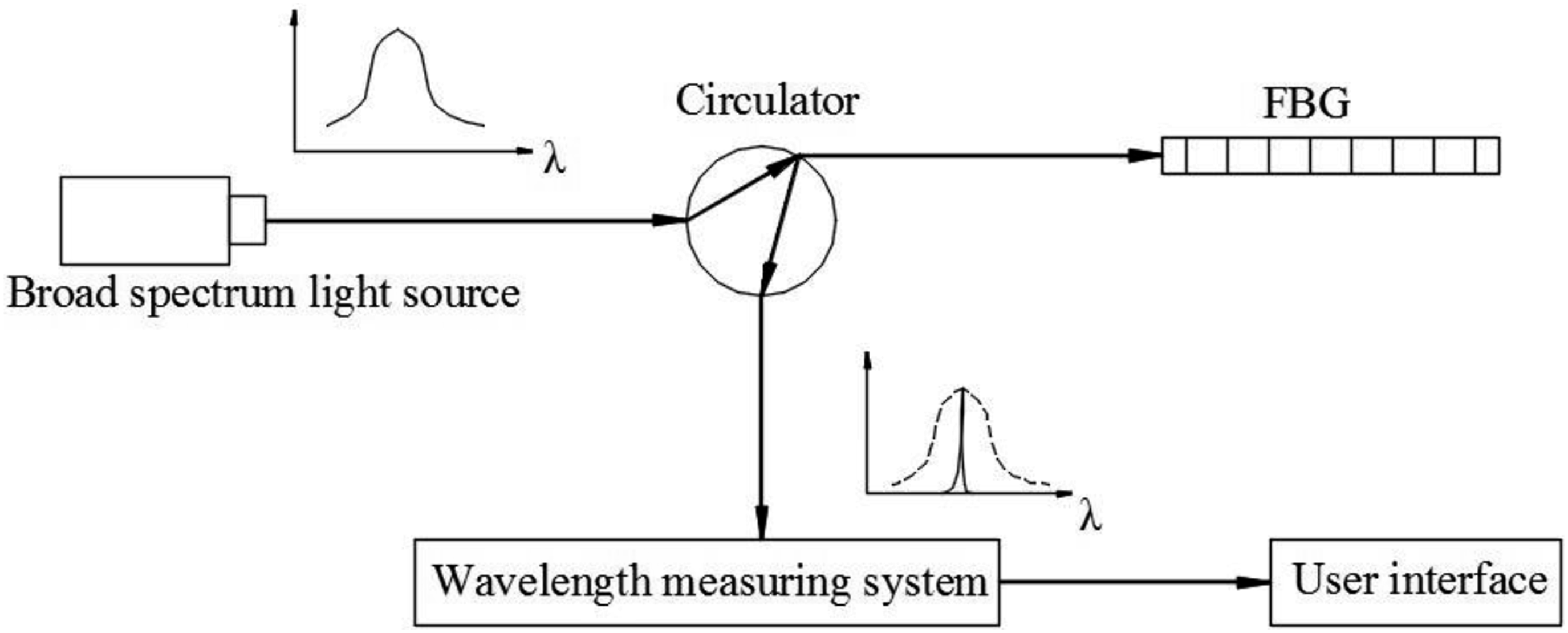
The relationship between

Two-end clamped OFSS
Because the bare fiber grating is very thin, with a diameter of only 125 μm, its shear resistance is poor and easy to be damaged. And the installation of the bare fiber grating has high requirements for construction, which is difficult to be applied in engineering practice. Therefore, it is necessary to encapsulate the bare fiber grating. The bare fiber grating applied in this experiment adopts the two-end clamped packaging technology, so it is called two-end clamped OFSS. The main idea is to use the steel casing to encapsulate OFSS, and install the clamping parts at both ends. Through this design, the strain is transferred to the fiber grating through the clamping parts. The two-end clamped OFSS can be pasted or welded on the surface of the structure to be tested. This design has the advantages of easy installation and replacement, good durability, etc., and is widely used in health monitoring of various large structures.
Figure 4 is a schematic diagram of the two-end clamped OFSS. As can be seen from the figure, the two-end clamped OFSS mainly includes three parts: FBG, clamping part, and fixed end. The FBG is glued and fixed in the clamping part. I is the distance between the two fixed, and I
f
s the distance between two clamping parts. Schematic diagram of the two-end clamped OFSS.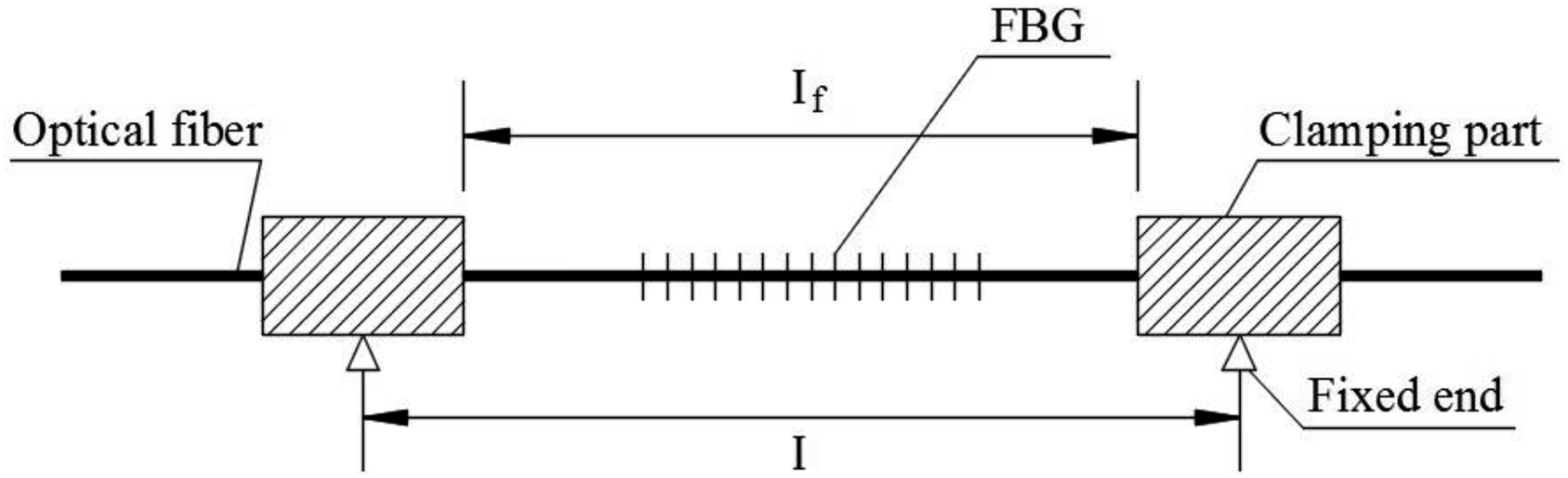
Based on material mechanics and optical fiber sensing principles, the final relationship between

As can be seen from equation (7), ε is proportional to
Two-end clamped OFSS is used to monitor the circumferential strain of pipeline to detect corrosion and leakage in this paper; its sketch map and photo are shown in Figure 5. As can be seen, the bare fiber is encapsulated in a steel tube and fixed on the pipeline through the clamping part. (a) Sketch map of a two-end clamped OFSS mounted on a pipeline and (b) photo of a two-end clamped OFSS mounted on a pipeline.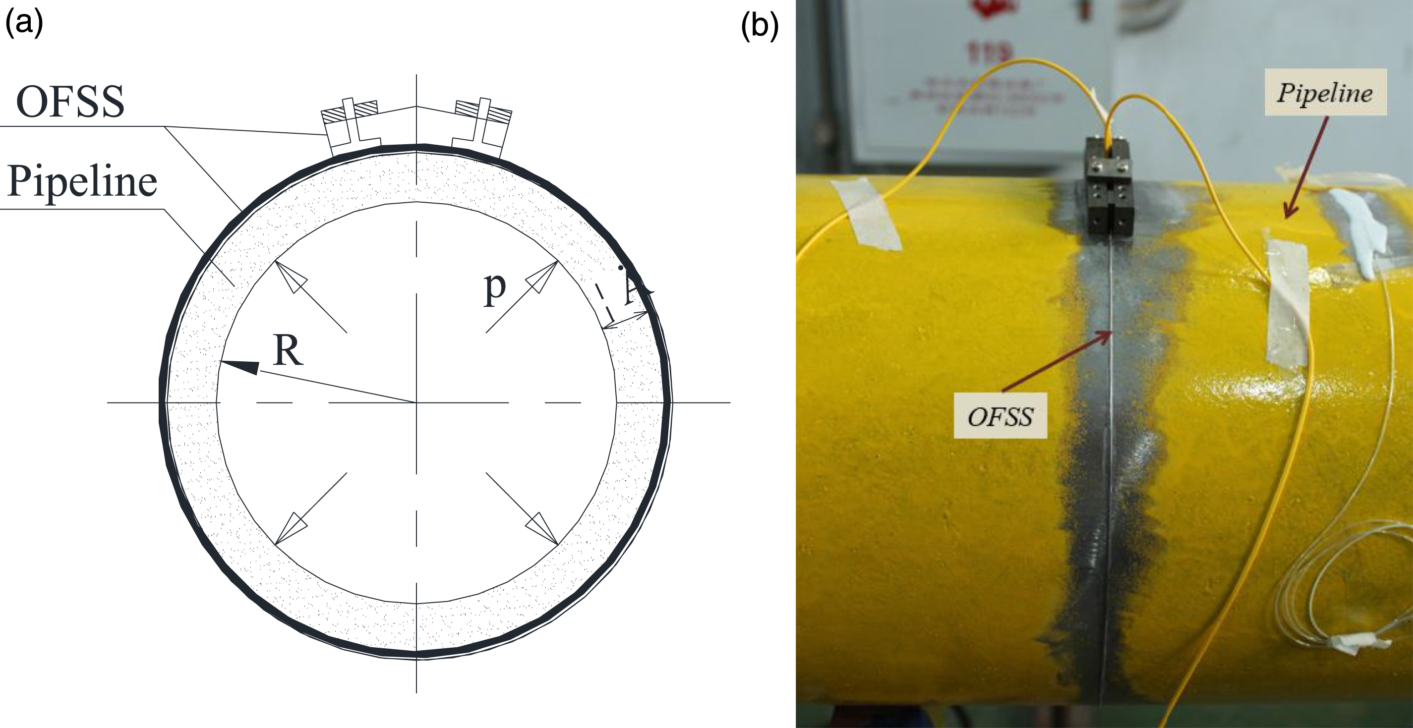
In addition, OFSS is not only sensitive to strain, but also sensitive to temperature, so a set of optical fiber sensors should be added in the actual situation to compensate for the strain generated by temperature. The experiments in this paper are all carried out in the laboratory, the temperature is basically constant, and so this aspect is not explained in this paper.
OFSS-based pipeline corrosion detection
Pipeline corrosion can be divided into two types: the first type is the corrosion caused by the fluid flow in the pipeline, which will cause the uniform decrease of the wall thickness of pipeline which is regarded as uniform corrosion; the second type is the local chemical corrosion or electrochemical corrosion in the pipeline, which will cause the loss of the pipeline material, that is, the local decrease of the wall thickness of pipeline. This situation is regarded as local corrosion, as shown in Figure 6. These two kinds of corrosion will cause the decrease of pipeline wall thickness, which will lead to the increase of the circumferential strain value of the pipeline according to equation (4). Therefore, pipeline corrosion can be detected by monitoring the circumferential strain. Local corrosion diagram.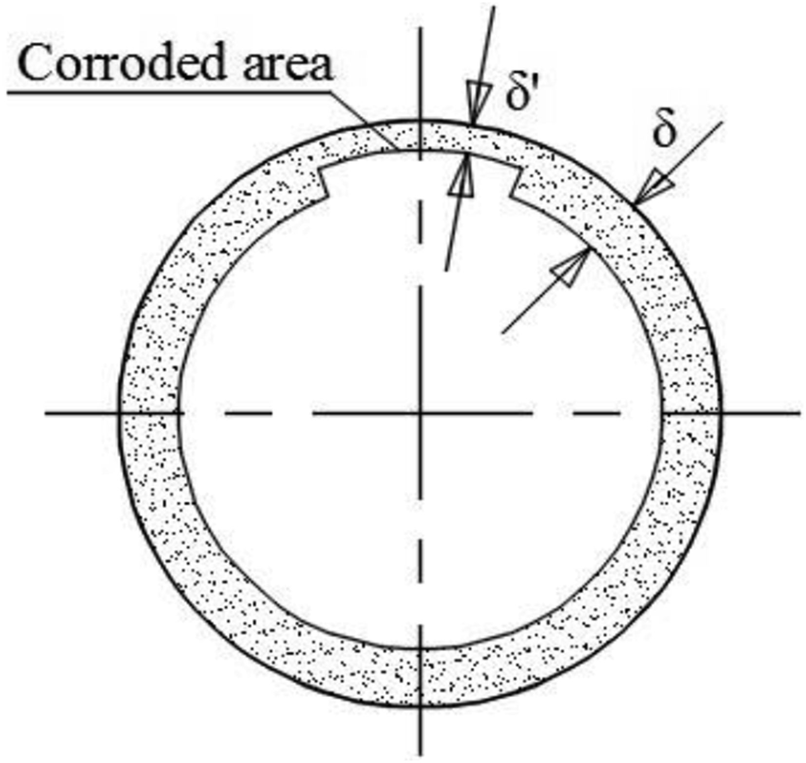
Although pipeline corrosion is theoretically random in terms of location, the survey findings indicate that it predominantly occurs in critical areas prone to corrosion, such as bends, valves, and so on. Consequently, OFSS can be strategically deployed in these aforementioned sections to enable effective monitoring of pipeline corrosion, as illustrated in Figure 7. OFSSs layout diagram of corrosion detection.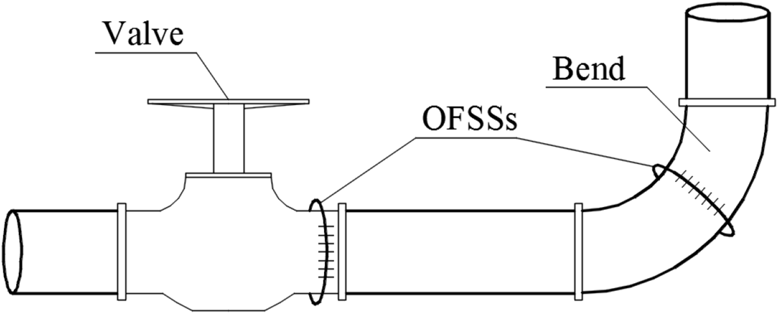
OFSS based pipeline leakage detection
Negative pressure wave (NPW) generation and propagation
According to the theory of fluid mechanics, when the pipeline is working normally, the pressure in the pipeline generally tends to be stable. When the pipeline leaks, the pressure difference between the inside and outside of the pipeline will cause the fluid at the leakage point to escape rapidly, and the fluid density at the leakage point will decrease, resulting in an instantaneous pressure drop. This instantaneous pressure drop travels up and down the pipeline in the form of a wave from the leakage point. If the internal pressure under normal operation of the pipeline is taken as the reference standard, the pressure wave generated by leakage is NPW. With the propagation of the wave, NPW will reduce the pressure along the pipeline to different degrees. As can be seen from equation (4), once the internal pressure of the pipeline is reduced, the circumferential strain of the pipeline will change and become smaller. Therefore, pipeline leakage can be detected by monitoring the circumferential strain of the pipeline as shown in Figure 8. Diagram of NPW generation and propagation.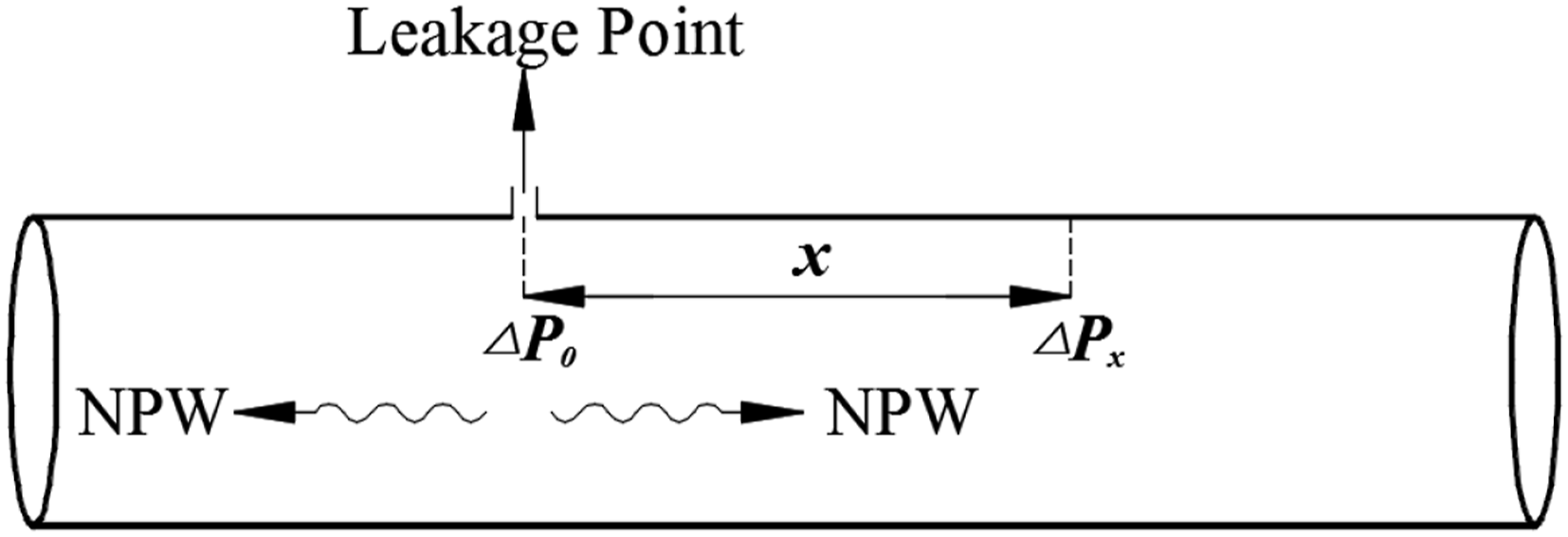
NPW is also a kind of wave, and the propagation of NPW is also a form of energy propagation. In this process, energy loss is inevitable. The mathematical model of NPW attenuation is as follows:

It can be seen from equation (8) that the farther away from the leakage point, the greater the attenuation of NPW value, the smaller the pressure drop in the pipeline, and therefore the smaller the circumferential strain of the pipeline. On the contrary, the closer the distance from the leakage point, the smaller the attenuation of the NPW value, so the greater the pressure drop in the pipeline, the greater the circumferential strain of the pipeline.
Principle of OFSS-based leakage detection
In this paper, the method of OFSS monitoring pipeline circumferential strain is used to detect leakage, and OFSSs are installed on the pipeline along the way. Once a leak occurs somewhere, the NPW generated and propagated will cause the change of pipeline circumferential strain. Therefore, by monitoring the pipeline circumferential strain, whether leakage occurs can be determined. By detecting the time difference of NPW propagation to different OFSSs, the leakage location can be determined by calculation as shown in Figure 9. OFSSs layout diagram of leakage detection.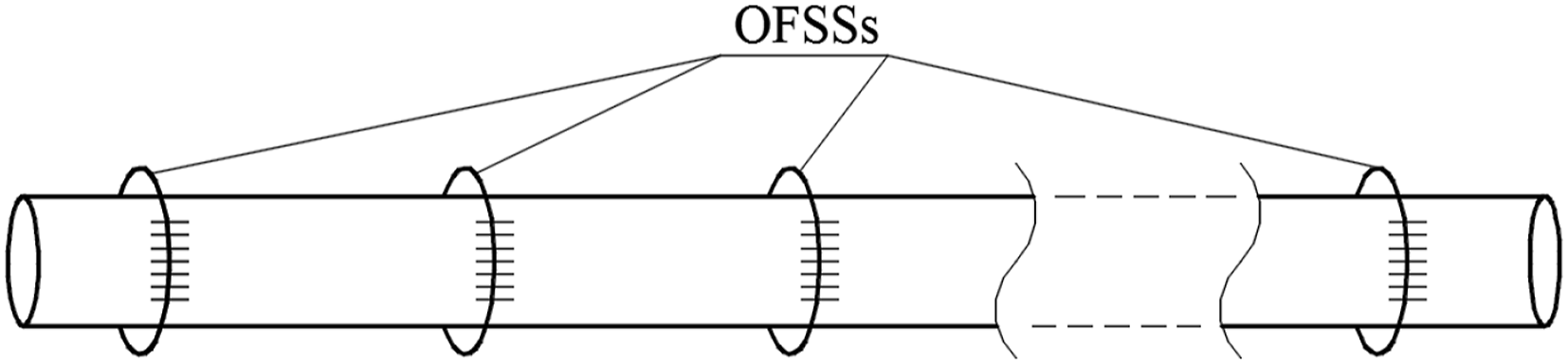
In addition, when locating the leak location, it is necessary to consider the influence of the flow of the fluid on the positioning, which is reflected in the propagation speed of the negative pressure wave from the leak point up and down. The velocity of the negative pressure wave propagating upstream to the leak point should be subtracted from the fluid velocity, and the velocity of the negative pressure wave propagating downstream to the leak point should be added to the fluid velocity. Especially in the propagation of gas, because the propagation speed of the negative pressure wave in the gas is about 300–350 m/s, this speed is not very large compared with the flow rate of the gas itself, so it has a greater impact on the location of the leak. The velocity of the negative pressure wave in the liquid is about 1000–1200 m/s, which is very large compared with the velocity of the liquid itself, and the influence on the location of the leak is small.
Experimental verification
The experimental bench consists of a steel pipe, an air compressor, a simulated leak point (ball valve control switch), a pressure sensor, and OFSS, as shown in Figure 10. The experimental process is roughly as follows: the air compressor pressurizes the pipeline to a certain pressure, and when the pressure is stable, the ball valve is opened manually to simulate leakage, and the ball valve is closed after leaking for a period of time. In this process, the pressure sensor has been collecting pressure data changes, and OFSS simultaneously collects pipeline strain and converts it into pressure changes (the functional relationship between strain and pressure changes has been obtained by OFSS calibration in the early stage). (a) System diagram of leakage detection experimental bench and (b) photo of leakage detection experimental bench.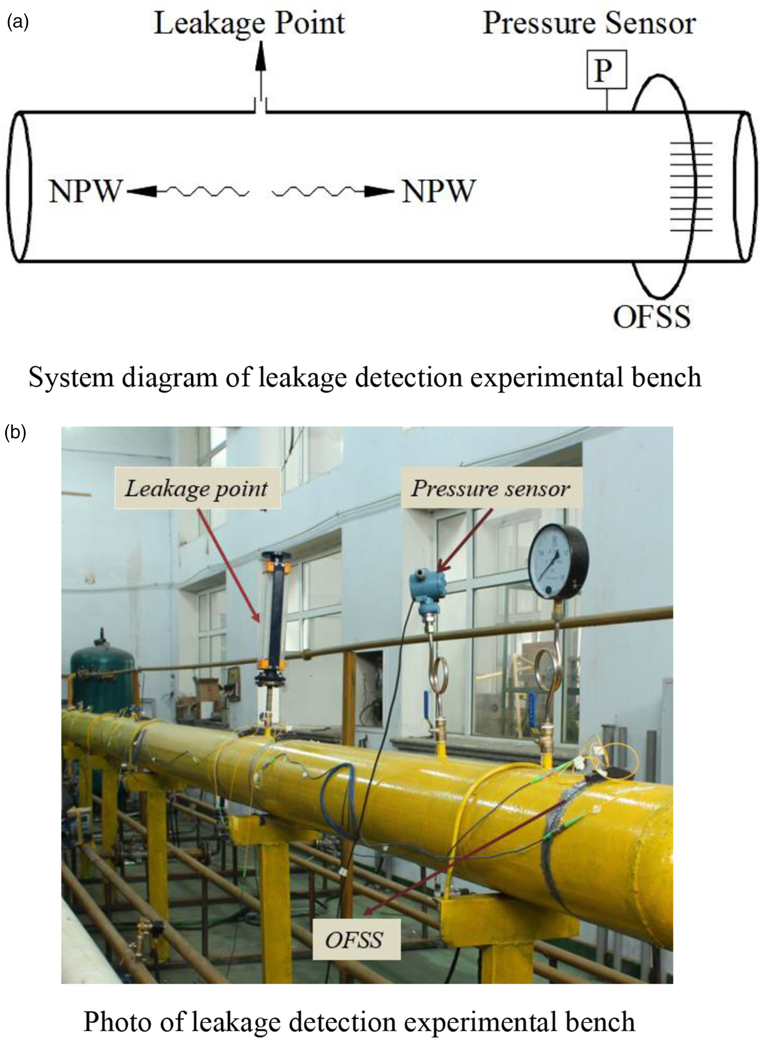
The experimental results are shown in Figure 11 and Figure 12. It can be seen from Figure 11, the pressure value in the pipeline was stable before the leak occurred. When the valve is opened, the leak begins and there’s a sudden drop in the collected pressure signal. This phenomenon occurs because the NPW generated by the leakage propagates to both sides of the leakage point and then causes the pressure drop where pressure sensor is located. This is consistent with the NPW theory. It can also be seen from Figure 11 that the pressure waveform has a sudden drop and a small pressure rise and then becomes stable. This is because the leakage in the experiment only lasted for a short time, when the valve is closed, the leak ends, the water crash phenomenon is formed in the pipeline, so that the pressure in the pipeline has a rise, and the formation of a small shock, slowly leveled off. Pressure change collected by pressure sensor. Pressure change collected by OFSS.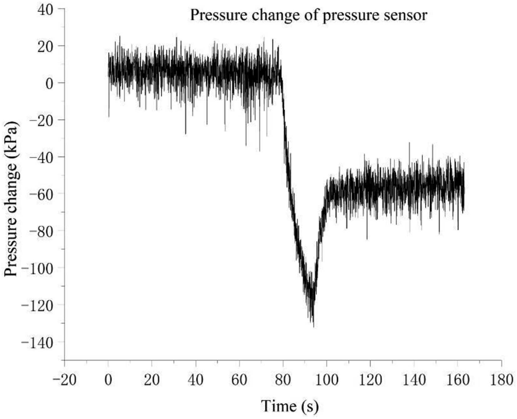
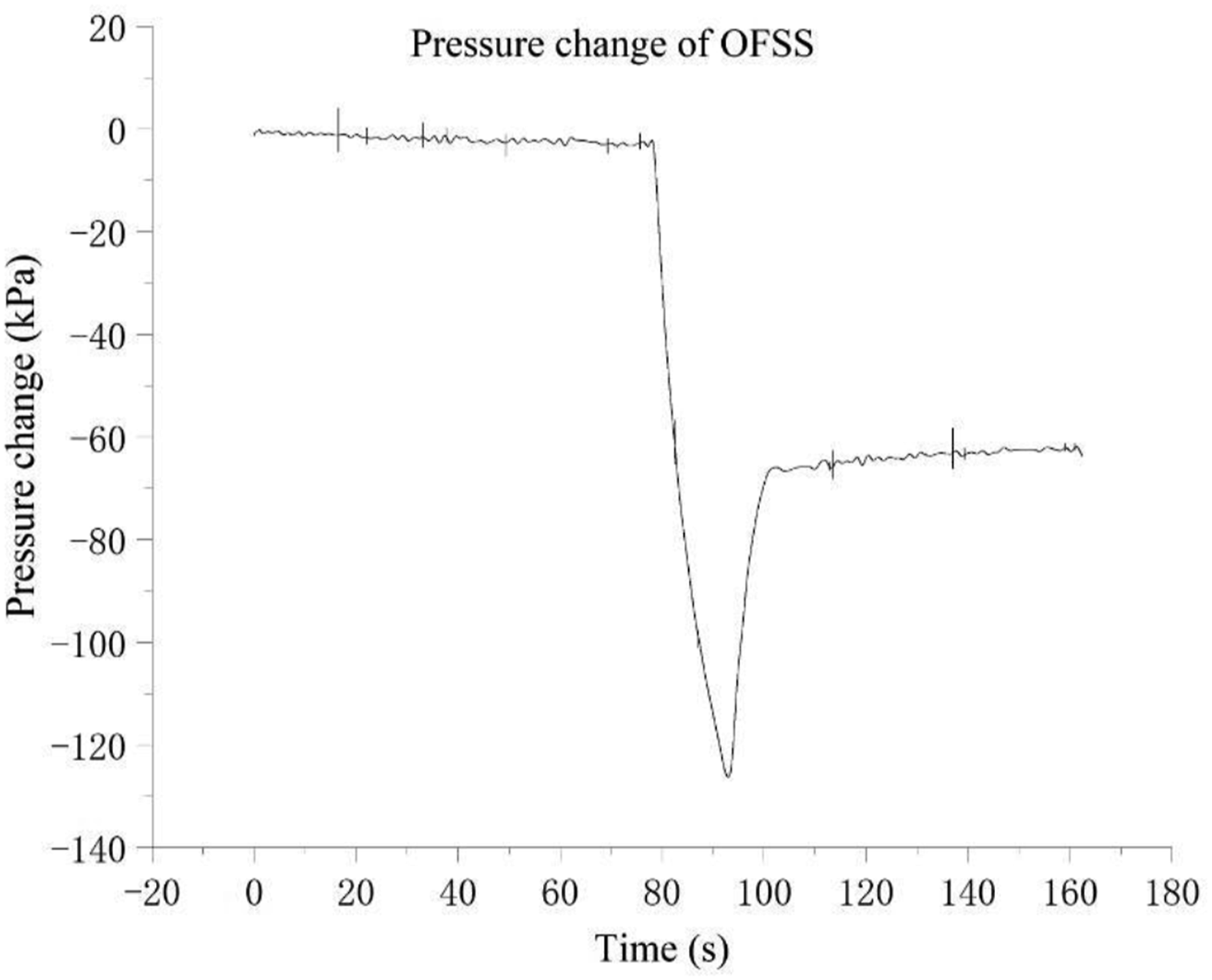
Figure 12 is the pressure signal collected by OFSS. It can be seen that the pressure change waveform collected by OFSS is consistent with that collected by pressure sensor. The measured pressure signal is stable at the beginning, but then there is a sudden drop. This is because after leakage occurs, the NPW propagates to both sides of the leakage point and causes pressure drop at the position of OFSS in the pipeline, resulting in circumferential strain change of the pipeline. OFSS detects a change in strain and thus a change in pressure in the pipeline. This fully shows that the application of OFSS to detect pipeline leakage is feasible.
The pressure range in the pipeline in the experiment was 0.05 MPa-1 MPa, and the experiment verified that as long as the pressure in the pipeline was higher than 0.05 MPa, the leakage could be well detected.
Since the occurrence of corrosion takes a long time, it is difficult to simulate under laboratory conditions, so this paper only conducts experimental verification on the pipeline leakage detection conditions based on OFSS. Limited by experimental conditions, this paper adopts gas pipeline for leakage detection, and in fact, this method is also suitable for liquid pipeline.
Conclusion
In this paper, the theory of circumferential strain measurement is introduced first, and the relationship between circumferential strain and internal pressure and pipeline wall thickness is obtained. Second, this paper introduces the principle of OFSS applied to strain measurement, and presents a two-end clamped OFSS which can be applied to pipeline strain measurement. The two factors that currently have the greatest impact on pipeline health are pipeline corrosion and pipeline leakage. The corrosion of the pipeline will affect the wall thickness and cause the circumferential strain of the pipeline. Pipeline leakage will produce NPW, and the propagation of NPW will further affect the pressure in the pipeline, and also cause the circumferential strain. Based on the above, finally, a pipeline corrosion and leakage detection method based on OFSS is proposed, so as to realize pipeline health monitoring. The experimental results show that this method is feasible for pipeline health monitoring.
Footnotes
Funding
The authors disclosed receipt of the following financial support for the research, authorship, and/or publication of this article: The authors acknowledge the Major Joint Research Project of Chengdu Vocational &Technical College of Industry (Grant: XJTD-2023-2).
Declaration of conflicting interests
The authors declared no potential conflicts of interest with respect to the research, authorship, and/or publication of this article.