




Abstract
Fuel cell air compressors play a crucial role in proton exchange membrane fuel cell systems, and their performance has a direct impact on the stable operation and energy efficiency of the system. In practical applications, the air compressor of the fuel cell system will be affected by the frequency and amplitude of changes in the air load. To effectively solve this problem, this study proposes and evaluates the control algorithm of fuel cell air compressors considering the characteristics of air load. Firstly, a control model of the fuel cell air compressor system including air load and back pressure valve model is established. Secondly, the input–output feedback linearization (IOFL) theory is adopted to globally linearize the control model of the fuel cell air compressor system. Finally, the Q-axis current of the improved speed loop is generated through the feedback of the air state quantity to correct the output torque of the air compressor. The simulation results show that this method ensures the accuracy of the model while achieving precise control of the rotational speed, effectively improving the adaptability and dynamic response performance of the air compressor, and guaranteeing the stability and efficiency of the fuel cell system.
Keywords
Introduction
With the increasing global demand for clean energy, 1 proton exchange membrane fuel cells (PEMFCs) have emerged as an efficient and low-emission energy conversion technology,2,3 gradually becoming an ideal alternative to traditional combustion engines. Their application in the automotive industry has been expanding significantly. 4 Made in China 2025 explicitly outlines the development path for fuel cell vehicles, further elevating PEMFCs to a strategic priority in national development. 5
The main components of a PEMFC (Proton Exchange Membrane Fuel Cell) include the fuel cell stack, air supply system, hydrogen supply system, water management system, and thermal management system. 6 In a PEMFC system, the air compressor, as the core component of the air supply, functions to compress and deliver external air to the fuel cell stack, providing the necessary oxygen supply for the reaction between hydrogen and oxygen. 7 The performance of the air compressor directly affects the stable operation and energy output efficiency of the fuel cell system.
Compared to traditional electric drive systems, the load conditions of automotive PEMFC air compressors are more complex: The air flow rate and pressure of a centrifugal air compressor are determined by its rotational speed, while the compression power demand results in a torque characteristic that is strongly correlated with the square of the speed, requiring ultra-high-speed operation to adapt to a steep torque-speed curve. 8 Additionally, the power demand of automotive fuel cell stacks varies frequently with driving conditions (e.g., acceleration, idle), 9 necessitating millisecond-level rapid adjustments in the air compressor’s load torque.
The complex variations in load torque can significantly exacerbate voltage control deviations, leading to dynamic instability in the d- and q-axis stator currents, which in turn causes torque and speed fluctuations with hysteresis.10,11 This easily results in delayed air supply flow and severe pressure oscillations. Pressure fluctuations and frequent overpressures can induce fatigue in the proton exchange membrane material, 12 which is one of the primary causes of degradation in the proton exchange membrane and fuel cell stack lifespan. 13 Moreover, these issues can lead to power reduction and system instability, posing threats to the system’s safety and reliability. 14
In the field of modeling research for fuel cell air compressors, there is a problem of high modeling complexity. The air dynamic response process in fuel cell systems involves complex mechanisms combining electrochemistry and fluid dynamics. Existing modeling approaches must account for multi-physics coupling effects, 15 resulting in high model complexity 16 and challenging parameter identification, which struggles to meet real-time control system requirements. To achieve accurate air compressor load torque control, there is an urgent need to develop a reduced-order compressor system model with multiple inputs and a single output (MISO) that can precisely characterize air load characteristics.
In the research field of high-speed electric drive systems, a systematic solution methodology for rotational speed fluctuations has not yet been fully established. Current studies predominantly focus on high-speed electric drive systems, typically employing second-order or third-order dynamic models for stability analysis. Regarding stability control, existing research emphasizes the mitigation of speed fluctuations induced by magnetic flux density harmonics and parameter disturbances. While this approach can satisfy the control requirements of conventional high-speed electric drive systems, it fails to account for other types of speed fluctuation mechanisms, such as nonlinear load disturbances.
Mahdavian M et al. (2016) proposed a PID-P-based torque control strategy to address torsional vibration issues in electric vehicle drive systems. However, their approach neglected the rotational speed difference between the drive motor and load end, resulting in insufficient model accuracy, and was limited to controlling only electromagnetic excitation disturbances. 17 Sariyildiz E et al. (2016) developed a robust position controller utilizing differential flatness and disturbance observer design. Their method employed estimated disturbances through state feedback control and direct feedback to eliminate both mismatched and matched disturbances, respectively. 18 Meanwhile, Riahi M R et al. (2015) introduced an improved Luenberger-based state feedback control structure, where the proposed observer measured both noise and load disturbances. However, both observers were designed for two-mass systems and are therefore unsuitable for rigidly-connected PEMFC air compressor structures. 19 Pham T et al. (2017) presented a feedforward-feedback strategy with dead-zone compensation for hybrid electric drive systems, employing a feedforward structure specifically for dead-zone compensation. 4 Li Qiong et al. (2016) focused on parameter optimization of Luenberger disturbance observers for pure electric vehicle drive systems. Nevertheless, constrained by the inherent structural limitations of this observer type, their approach could not implement additional feedback channels, directly resulting in overshoot phenomena during system response and consequently degraded control performance. 20
In light of the aforementioned issues, the control strategy for PEMFC air compressors must fully account for the influence of dynamic air load characteristics. This enables real-time speed tracking of power demand to achieve precise oxygen supply. This paper focuses on the following: (1) Developing a refined control model for PEMFC air compressors based on characterized load dynamics. (2) Proposing a disturbance-resistant speed control methodology. (3) Validating its performance under various operating conditions through simulation studies.
The proposed approach provides theoretical support for enhancing the stability and efficiency of fuel cell systems.
Air compressor and aerodynamic load model for PEMFC systems
The PEMFC centrifugal air compressor primarily consists of a high-speed permanent magnet synchronous motor (HSPMSM) and a two-stage impeller. Its air load characteristics are determined by downstream air path components, including intake/exhaust manifolds, the cathode side of the fuel cell stack, and the backpressure valve, as illustrated in Figure 1. This chapter establishes the model through two key aspects: (1) compressor modeling and (2) dynamic air load modeling. The developed model enables simulation of the compressor’s flow rate, pressure characteristics, and load behavior, while specifically accounting for load torque variations across different operating points. This provides fundamental support for system load prediction and control strategy design. PEMFC air supply system schematic diagram. Simplified fitting result of air compressor flow MAP (flow rate: kg/s; rotational speed: kr/min).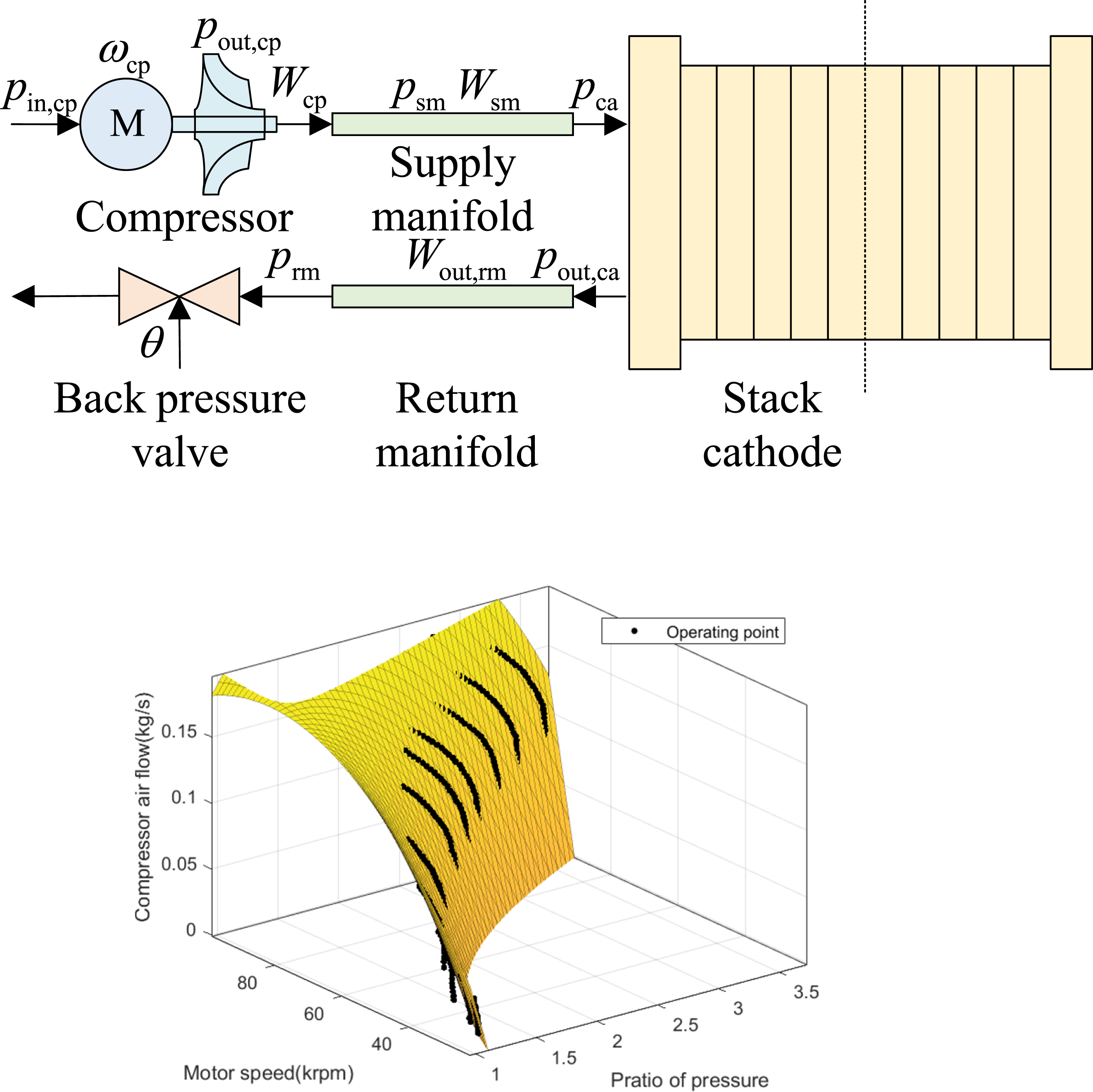
Air compressor model for PEMFC systems
The air compressor model is divided into the air dynamic behavior model and the drive motor model. For the construction of the scalar mathematical model of HSPMSM, to simplify the analysis, the following assumptions need to be made when establishing the mathematical model of HSPMSM in this section: The magnetic saturation of the core is not considered; hysteresis loss and eddy current loss are not considered; the high-order harmonic components generated during operation are not considered; the stator current in the motor remains three-phase symmetrical.
Based on the assumptions established in this section and the circuit principle of the permanent magnet synchronous motor model, the permanent magnet synchronous motor model driven by the air compressor can be established.
Modeling of compressor drive motor
Based on the common structure of PEMFC centrifugal air compressors and the product data of the FCC400H model from the manufacturer Splus Turbo, it is known that most centrifugal air compressors currently use oil-free air bearings to support the drive motor rotor. The low dynamic viscosity results in an extremely small damping coefficient B of the motor rotor under steady-state high-speed conditions (Ncp > 104 rpm). Therefore, the following simplifications are made: (1) The influence of the rotor damping coefficient on the rotor mechanical equation is neglected.
The rotational speed dynamic response of the rotor of the drive motor HSPMSM is calculated by equation (1.1):

Among them,
The electromagnetic torque of the drive motor HSPMSM is calculated by equation (1.2):

Most HSPMSM are of stein-pole design,
Dynamic air behavior modeling for compressor systems

Fit coefficient.

Aerodynamic load model for air compressor in PEMFC systems
In addition to the drive motor and impeller of the air compressor, it is also necessary to analyze and model external components such as air pipelines and back pressure valves to study the influence of air load characteristics. This section establishes a nonlinear model of air load considering flow rate, pressure, and related air states. Among them, parameters such as flow rate and pressure are based on the normal operating range data of the FCC400H model air compressor with a rated power of 30 kW of Shijia Toubo, and the load torque is established according to the thermodynamic equation.
Stack cathode modeling
This paper only considers the dynamic flow behavior of the gas at the inlet and outlet of the cathode of the stack. For the electrochemical reaction, this section accounts for the three main gas components in air—oxygen, nitrogen, and water vapor—to derive the cathode pressure. Per mass flow continuity, the cathode gas mass change rate equals the inflow-outflow difference, the masses of each gas in the cathode flow field satisfy: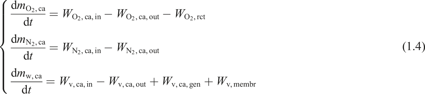
Among them,
Considering the effects of both the humidification ratio at the cathode inlet and the oxygen mass fraction, a proportional correlation is derived. The flow rates of each gas component at the cathode inlet can be expressed by the following formula: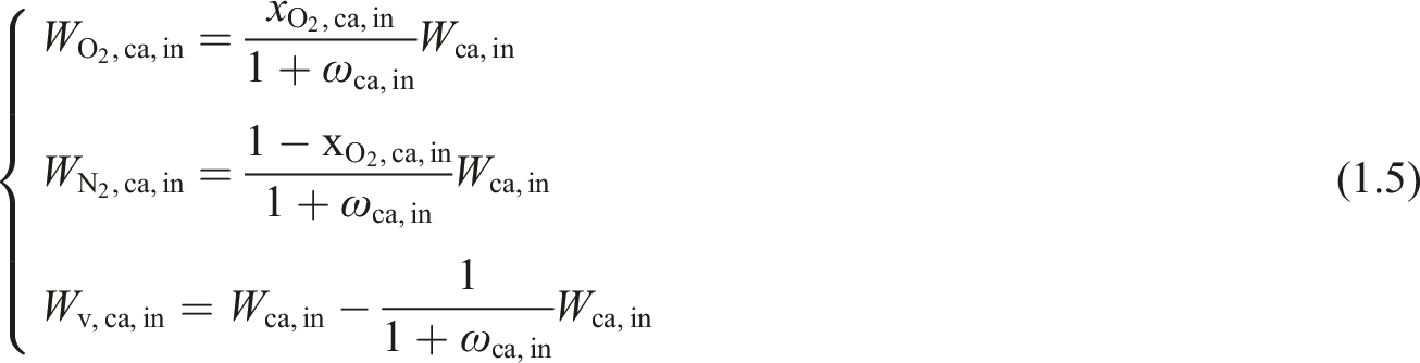
Among them, 
Among them,
After undergoing chemical reactions in the stack, the process of the mixed gas being discharged from the cathode flow field is similar to its entry, and the discharge flow rate satisfies the following formula:
Among them, kca,out is the flow coefficients at the cathode outlet; pca and prm are, respectively, the cathode pressure and the reflux pipe pressure(Pa). Next, the flow rates of each gas at the cathode outlet can be calculated: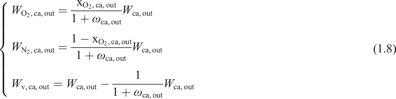
The oxygen consumption rate and water generation rate in the fuel cell stack are calculated as follows
21
:

According to the saturation state of the gases, water in the cathode flow channel exists in both gaseous and liquid phases. Based on the saturated water vapor pressure, the maximum mass of water existing in vapor form in the cathode can be expressed as follows:

Based on the saturated state of the gas, the mass of water inside the cathode and the maximum water vapor mass satisfy the following relationship:
Based on the ideal gas equation 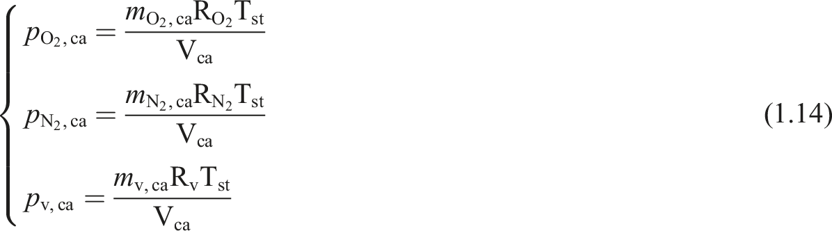

Air load torque modeling
In the modeling of fuel cell air compressors, the modeling of load torque is one of the key aspects. By establishing a reasonable mathematical model to represent the response characteristics of the air compressor under different load conditions, the load torque of the fuel cell air compressor can be accurately predicted, and a basis can be provided for the optimization of the control strategy.
For the adiabatic compression process of an ideal gas, the compression work per unit mass of gas (W) is given by the thermodynamic formula:
From equation (1.6), the ideal power of the air compressor 
The relationship between mechanical power and torque is given by:
By substituting equation (1.17) into equation (1.18) and rearranging, the load torque 
For an ideal gas, the outlet temperature 
However, in practical compression processes, irreversible factors such as friction and heat loss exist. The relationship between the actual temperature and the ideal temperature is given by:
Substituting equation (1.20) into equation (1.21) and rearranging yields the outlet air temperature Tout,cp (K)of the compressor:
Intake manifold modeling
In PEMFC air compressor systems, accurate pipeline modeling is crucial for investigating fluid dynamic characteristics. The key challenge lies in effectively simulating both the mass flow rate and pressure dynamics of the compressor piping system.
According to the equation of conservation of mass:
Among them Wsm,in is the air flow rate entering the cathode gas supply pipeline(kg/s), which is equal to the compressor outlet flow rate Wcp(kg/s); Wsm represents the gas flow rate flowing out of the gas supply pipeline(kg/s). msm represents the mass of gas accumulated in the gas supply pipeline(kg).
The gas pressure psm inside the intake pipeline is calculated based on the ideal gas state equation. It is assumed that the gas temperature inside the supply pipeline is equal to the gas temperature at the outlet of the air compressor Tout,cp:
Among them, Ra is the gas constant of air, the volume of the Vsm gas supply pipeline (m3), and Tsm is the internal gas temperature (K) of the pipeline.
Given the relatively small gas pressure differential between the supply pipeline and cathode inlet, the mass flow rate Wsm through the supply pipeline can be expressed using a linear relationship with this pressure drop:
Among them, kout,sm is the flow channel coefficients at the outlet of the gas supply pipeline, its physical meaning is the mass flow rate per unit pressure difference, reflecting the ease of gas passage through the pipeline. Its value is determined by the pipeline’s geometric dimensions, gas properties, and flow conditions. And pca is the total gas pressure inside the cathode(Pa).
Modeling of Recirculation manifold and backpressure valve
During the process where gas exits the cathode flow field and enters the backpressure system, the temperature variation of the cathode gas can be considered negligible. Under this isothermal condition, the pressure characteristics in the backpressure pipeline can be described using the isothermal equation. The internal pressure of the exhaust pipeline can be expressed as follows:
Among them Vrm is the volume of the exhaust pipe (m3); Wca_out is the gas flow rate at the cathode outlet(kg/s). Approximately, this flow rate is regarded as the cathode gas flow rate entering the back pressure system. Wrm_out is the gas flow rate at the exhaust pipe outlet, and Trm is the gas temperature in the exhaust pipe(K).
The outlet mass flow rate of the back pressure valve can usually be divided into two regions according to the critical pressure ratio, which can be expressed as follows:
Fourth-order control model of air compressor with precise characterization of aerodynamic load dynamics
In practical PEMFC systems, the control objective of the air compressor is to regulate the q-axis current to ensure the compressor speed tracks its reference value, thereby enabling precise delivery of oxygen at the required flow rate and pressure to maintain system power output performance. To facilitate speed control under complex load conditions, a fourth-order control-oriented compressor model is developed based on the air-load-characteristic-integrated models presented in Sections 1.1 and 1.2. Based on the majority of research on air system modeling, the following assumptions are made for the established control model: (1) Constant temperature and humidity in the cathode flow channel. (2) Negligible gas transport losses and time delays. (3) Instantaneous hydrogen response to air pressure variations to meet power demands.
The formulation of the aforementioned assumptions aims to simplify model complexity and focus on the core air dynamics relevant to air compressor speed control, including the relationships among pressure, flow rate, and power in the air path and the cathode of the fuel cell stack.
For Assumption (1), in practical air compressor control systems, variations in temperature and humidity are relatively slow compared to pressure dynamics, making it feasible to neglect their changes within the control time step. However, this assumption may reduce the model’s prediction accuracy under rapid load changes and extreme temperature/humidity conditions, and its applicability depends on the effectiveness of the external thermal/water management system. For Assumption (2), it is reasonable in cases where the air supply path is short and simple, significantly reducing the model’s order and complexity, which benefits control strategy design. However, this assumption neglects pipeline pressure loss and transmission delays, which may affect the model’s accuracy in real-world systems with complex pipelines, thereby limiting its generalizability in engineering applications to some extent. For Assumption (3), since hydrogen is supplied from the storage tank via a fast-response solenoid valve, its dynamics are significantly quicker than those of the air supply system. Therefore, when designing the air system controller, hydrogen can be considered ideally controlled, and its dynamics can be neglected. However, this assumption may lead to the model’s inability to capture power tracking delays caused by hydrogen response lag or poor control under conditions of insufficient supply or system faults. Consequently, it is not suitable for scenarios involving the study of fully coupled system dynamics or hydrogen subsystem performance.
In summary, the fourth-order model established in this chapter, under the stated assumptions, is suitable for analyzing the response of air compressor speed control to load-induced gas dynamics, particularly under conditions of well-managed system thermal/water management, simple air supply paths, and rapid hydrogen supply response. The model’s primary limitations lie in its simplified treatment of fast dynamics and complex or fault conditions. Future work may consider progressively relaxing key assumptions to enhance the model’s predictive capability and engineering applicability across a broader range of operating conditions.
Under these assumptions, a fourth-order PEMFC air compressor model is proposed by incorporating key air dynamics in both the compressor and intake gas pipeline:
Definition of state variables.
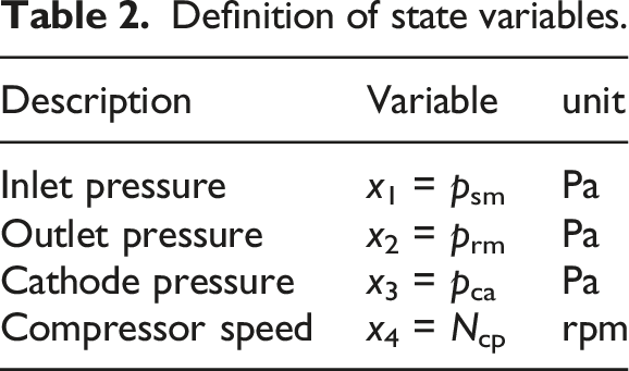
Based on the modeling principles of the air compressor and air dynamic load presented in Sections 1.1 and 1.2, a fourth-order state-space model is derived and established as shown in Figure 2. The state equation for supply pipeline pressure is derived from equation (1.24): The derivation steps of the fourth-order equation.

Here, 
Here, ψ(x2) is a function of the return pipeline pressure x2, specifically defined as equation (1.27).
The cathode pressure in the fuel cell stack can be expressed as the sum of partial pressures of oxygen, nitrogen, and water vapor:
Since water exists in both gaseous and liquid states within the fuel cell stack, accurately capturing the dynamics of cathode water vapor would significantly increase the complexity of the control model. Furthermore, as the water vapor partial pressure in the cathode cannot exceed the saturation vapor pressure and its contribution to the total pressure is relatively small, this study approximates the water vapor pressure using the saturation vapor pressure, thereby neglecting water vapor dynamics.
Based on equation (1.4), the dynamics of the oxygen and nitrogen partial pressures in the cathode can be derived as follows:

Based on the dynamic differential equations for oxygen and nitrogen derived above, the cathode pressure dynamics of the fuel cell stack can be obtained by summing equations (2.5) and (2.6) and rearranging:
To further optimize the model, this paper utilizes the following assumptions:
Here, k is taken as 0.026. The rationality of this assumption has been proved in reference.
22
Thus, substituting equation (2.9) into equation (2.8), the following equation can be obtained:
Substitute equations (1.19) and (1.2) into mechanical equation (1.1) to derive the rotational speed state equation of the air compressor:
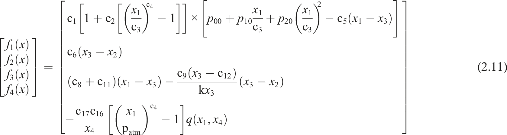



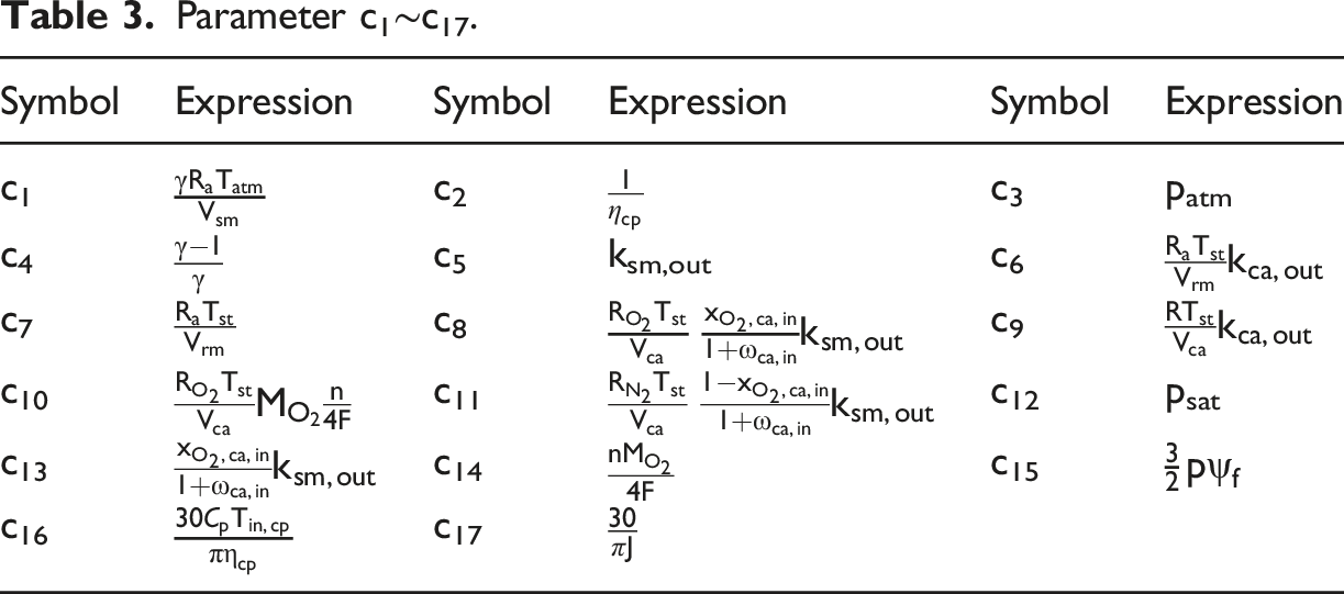
Parameter c1∼c17.
Speed Loop Control Strategy Based on I/O Feedback Linearization
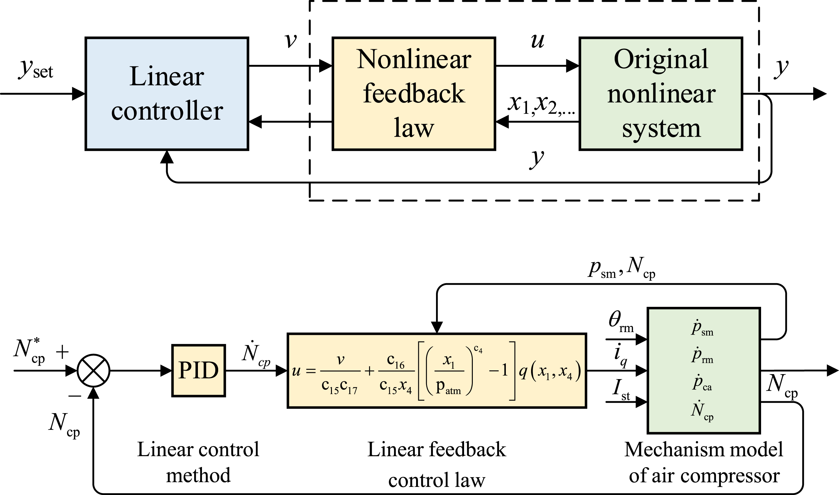
I/O feedback linearization (IOFL) can transform the input–output relationship of a nonlinear system into a linear one, thereby converting the control problem of a nonlinear system into a more well-established linear system control problem. By repeatedly differentiating the control objective function, a direct relationship between the control objective and the input variables is obtained, and a corresponding feedback control law is constructed to achieve linearization. Furthermore, the global stability of the system can be ensured through the linearized system structure.
Exact IOFL theory for single-input single-output systems via differential geometric methods
For a multivariable nonlinear system:
Here, x is an n-dimensional state vector; u is the input variable; y is the output variable; f(x) and g(x) are n-dimensional smooth vector fields; and h(x) is a smooth scalar function. The output is repeatedly differentiated until the control input appears. By successively differentiating y, we obtain:
Until there exists a positive integer r such that
The control law is constructed in 
Then we obtain: Feedback linearization schematic diagram. Speed Control Loop Architecture Based on Precisely Characterized Load Model.
The concept of Lie derivatives was applied during the differentiation process. Therefore, this paper introduces its definition as follows: The Lie derivative of σ(x) along q(x) is given by: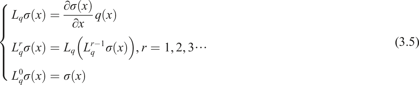
Speed loop design for PEMFC air compressor based on IOFL with load characterization

Definition of input and output variables.
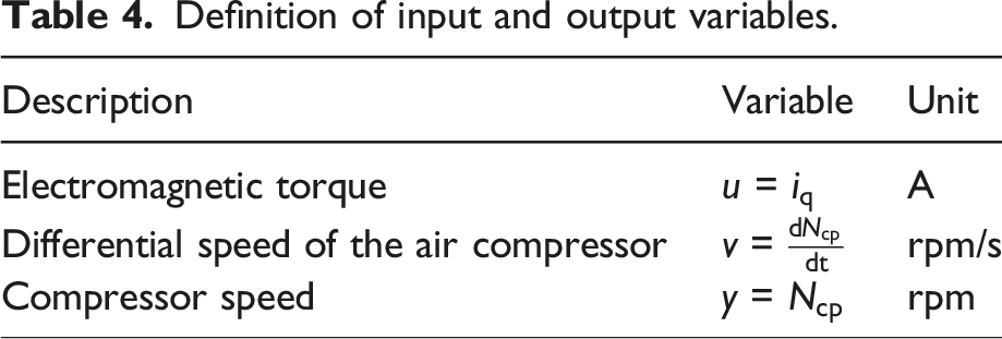
We obtain r = 1<2 = n, which indicates that the model can be linearized.
Proceeding to design the exact feedback control law:
Evidently, this feedback action compels the nonlinear dynamical system to degenerate into a pure integrator form of
The proposed speed-loop architecture is illustrated in Figure 3. Based on the air compressor control model characterizing air-load characteristics established in Chapter 2, with the q-axis drive current of the air compressor as the control input, we design an IOFL-based speed loop for tracking control of the compressor speed. An error feedback control law is designed to obtain the virtual control input v. A proportional-integral-derivative (PID) controller is employed to compute the virtual input v in the system, and the actual control input u is derived through the feedback control law, enabling the system to achieve the following: (1) Desired dynamic response characteristics. (2) Effective rejection of load disturbances. (3) Steady-state error-free tracking regulation.
Comparative simulation and validation
Parameters of PEMFC compressor.
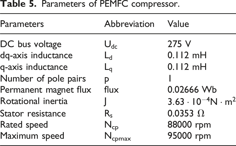
Dynamical verification of the 4th-Order reduced model
To validate the accuracy of the proposed fourth-order model, comparative studies were conducted using the PEMFC air compressor and load mechanistic model developed in Chapter 1 as the control plant. The test sequences for fuel cell stack current, q-axis current, and backpressure valve opening were configured as shown in Figure 4. Comparative results of dynamic variables for the air compressor and air path are presented in Figure 4. Compressor test working conditions. (a) q-axis current input, (b) backpressure valve opening, and (c) stack current. Model accuracy verification. Comparative simulation between conventional and proposed control approaches. Comparative simulation between conventional and proposed control approaches under parameter variations.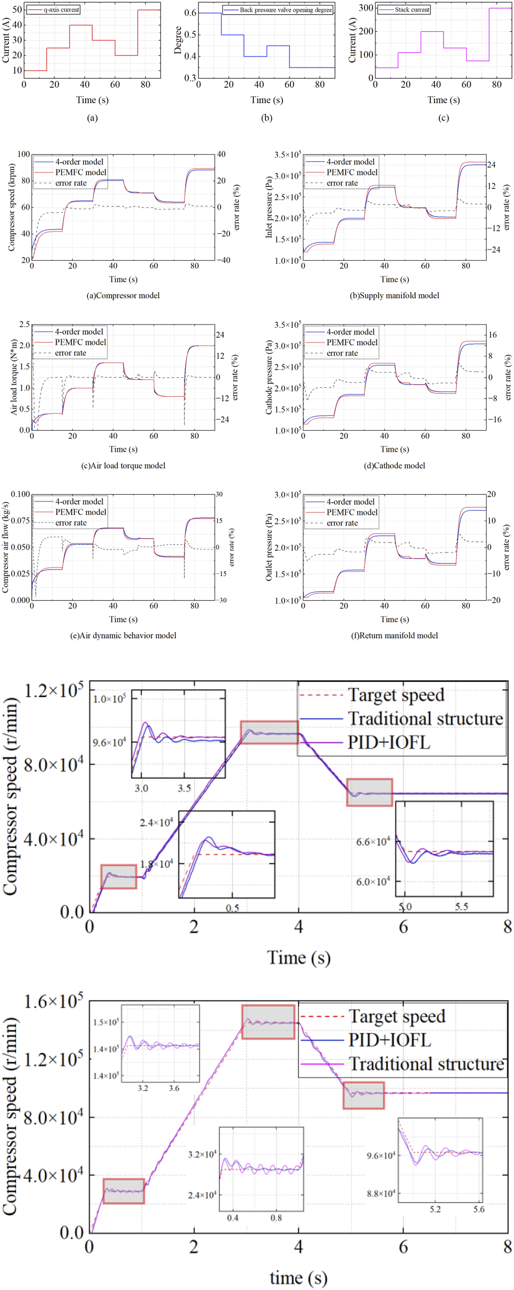

MAPE of compressor speed and air load torque.

Across all time intervals, the MAPE values for both oxygen excess ratio and cathode pressure remain below 3.0%, with an overall average below 1.3%. This demonstrates the high accuracy of the fourth-order model. The minor discrepancies between the fourth-order model and the actual plant primarily stem from unmodeled water dynamics and neglected actuator delays. In conclusion, the proposed fourth-order model not only reduces computational complexity but also effectively captures the air dynamics of the PEMFC system, making it suitable for subsequent control strategy design.
Simulation validation of the proposed speed control loop strategy
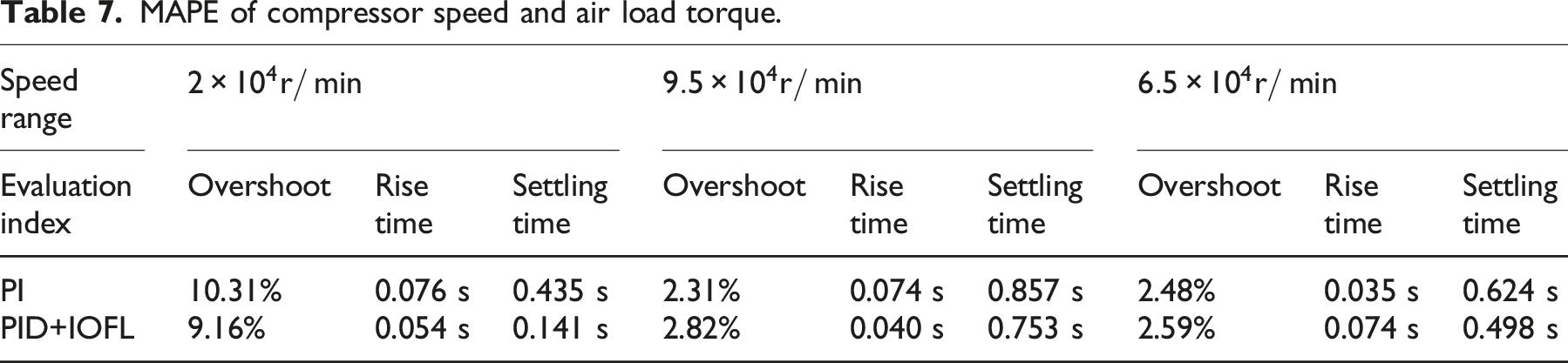
To validate the reliability and effectiveness of the proposed speed control loop structure incorporating air load characteristics, simulation studies were conducted in MATLAB/Simulink to evaluate the speed control strategy for the PEMFC air compressor. A comparative analysis was performed against conventional speed control loop approaches. The reference speed operating conditions are shown in the accompanying figure, while the comparative results of compressor speed regulation performance are presented in Figure 4.
MAPE of compressor speed and air load torque.
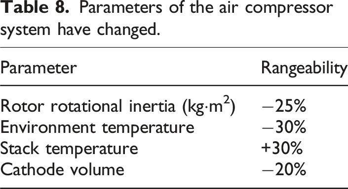
Parameters of the air compressor system have changed.
Summary
This study presents an input–output feedback linearization (IOFL)-based speed control method for PEMFC air compressors that addresses two critical challenges: (1) precise characterization of complex load dynamics across operating points and (2) accurate speed regulation under nonlinear load variations. The methodology involves three key contributions: First, a fourth-order control-oriented model is derived from first-principles PEMFC system dynamics and implemented in a simulation platform. Second, IOFL techniques are applied to effectively linearize the compressor’s nonlinear dynamics. Third, a hybrid PID-IOFL current loop architecture is developed to enhance control performance. Comprehensive simulations demonstrate the model’s accuracy in capturing both steady-state and transient characteristics of all state variables, while comparative results show the proposed structure achieves superior performance to conventional methods—reducing overshoot to <3%, improving response speed by 30%, and enhancing tracking precision. These advancements significantly improve the dynamic regulation capability of PEMFC air supply systems.
To further enhance the depth, practicality, and generality of the research, future work could focus on the following directions: (1) Experimental Validation and Platform Development: Implement the designed feedback linearization controller on a real hydrogen fuel cell test bench to evaluate its robustness and control performance in addressing practical system nonlinearities, parameter perturbations, measurement noise, and environmental disturbances, thereby validating simulation conclusions. (2) Real-Time Controller Implementation and Optimization: Deploy the control algorithm on embedded real-time controllers (e.g., dSPACE) to investigate computational efficiency and address implementation challenges in real-world engineering applications. (3) Adaptation Study for Other Fuel Cell Types: Explore the applicability of the proposed control strategy in different fuel cell systems, such as stationary SOFC/MCFC air compressor control, and analyze the impact of system characteristic differences on controller design for targeted improvements.
Footnotes

Declaration of conflicting interests
The authors declared no potential conflicts of interest with respect to the research, authorship, and/or publication of this article.
Funding
The authors received no financial support for the research, authorship, and/or publication of this article.