




Abstract
Forklifts, as one of the most commonly used transportation tools in current engineering construction, have extremely high research value. With the increasing energy-saving requirements of the forklift industry, energy-saving improvement of the lifting system in the hydraulic lifting system of forklifts has become a research hotspot. To optimize the energy saving of the forklift hydraulic lifting system, this research proposes to use the secondary regulation technology to optimize it. The gravity potential energy generated in the lifting of the load is recovered through the secondary components, and stored in the energy accumulator to provide energy for the operation of the system, to reduce the energy consumption of the engine. The experimental results show that compared to traditional lifting systems, the proposed secondary regulation lifting system saves 29 kJ of energy consumption and can achieve an efficiency of 87.8%. In addition, the load weight, lifting speed, and energy storage capacity all have varying degrees of influence on the energy consumption of the improved secondary regulation system. When the load weight is 5 kg and 15 kg, the energy consumption difference between the two is 75 kJ, and the displacement difference is 0 m. When the lifting speed is 0.1 m/s and 0.3 m/s, the displacement distance difference between the two is 1.5 m, and the energy consumption difference is 123 kJ. When the energy storage capacity is 5 L and 11 L, the displacement distance difference is 0.1 m, and the energy consumption difference is 89 kJ. Therefore, the improved secondary regulation and lifting system proposed in the study has high energy-saving performance.
Introduction
Forklift is an industrial mechanical equipment used for handling and stacking goods. It usually has two parallel steel forks that can be inserted underneath the cargo, then lifted and moved to the destination. The background of forklifts can be traced back to the early 20th century, and their development is closely related to industrialization and the rise of the logistics industry. With the rise of the Industrial Revolution, the production and logistics industries have developed rapidly. More and more goods need to be transported and stacked between factories, warehouses, and transportation centers, which has led to the emergence and development of forklifts. The development of the logistics industry has led to an increase in the standardization of goods, and pallets have been widely used as a common container for goods. The combination of forklifts and pallets greatly simplifies the handling and stacking process of goods. The emergence of forklifts has significantly improved the efficiency of handling and stacking goods. Compared to manual handling, forklifts can complete tasks faster and more accurately, while reducing labor costs and the need for human resources. However, the working environment of forklifts is harsh. In order to ensure the safety and reliability of their operation, it is necessary to design their hydraulic system. 1 The design of traditional forklift hydraulic lifting (FHL) systems mainly considers functionality, but lacks attention to energy consumption. With the increasing demand for energy conservation and environmental protection in the industry, the optimization of energy conservation for forklifts has gradually become a research hotspot in the field of forklifts. Among them, FHL, as an important structure of forklifts, is of great research significance for energy conservation optimization. 2 To reduce the energy consumption of the FHL system, this research proposes to improve the FHL system by using the secondary regulation (SR) technology. This technology recovers the gravity potential energy generated when the system load rises and falls through the design of secondary components, and stores it in the energy accumulator to provide energy for the operation of the system and reduce the energy consumption of the generator. 3 The SR lifting system can store the gravitational potential energy during system descent in the energy storage device by switching the motor operating conditions. And the system can also release the gravitational potential energy through the rotary motor when the fork rises, and use it for power support.
The research content is mainly divided into four parts. The first part is an overview of the development of energy-saving technologies in the forklift industry and the current application status of AMESim. The second part is a brief description of the main methods used in this study, and the third part is the model results obtained through the use of methods and an analysis of the results. The fourth part is a summary of all the above studies and prospects for future research.
Related works
Forklifts, as important tools for transporting and loading and unloading goods, have a high demand for energy consumption during use. In response to the call for energy conservation and emission reduction, many researchers have conducted energy-saving optimization on different systems of forklifts. Khoei et al.’s mixed integer programming formula planned energy-saving routes for the transportation of forklifts, and also considered factors such as load weight and moving speed in the route planning, realizing dynamic programming of energy-saving routes. The experimental findings indicated that this route had significant energy-saving effects. 4 Zhang et al. implemented the energy-saving concept into the temperature controlled cooling system of forklifts and optimized the hydraulic drive fan system using a pilot operated electro-hydraulic proportional valve, aiming to reduce heat dissipation and energy consumption in a low-speed operation. The research outcomes denoted that the system could reach the preset speed in 5 seconds at 40°C, with a power of 80%, and had high heat dissipation and energy-saving efficiency. 1 Bedrunka et al. set up a hydrogen storage system to replace the engine to provide energy for the operation of forklifts, and then designed the system’s hydrogen storage capacity to meet the operational needs of forklifts through parameter design. After verification through model simulation experiments, the findings expressed that the energy provided by the system met the needs of forklifts and had high practicality. 5 Cheng et al. conducted a management study on the power system of electric forklifts using a stochastic model to predict energy management policies. The performance of the power system was analyzed by analyzing the operating conditions and energy consumption of the forklift power system. The experimental outcomes indicated that electric forklifts using supercapacitors had a relatively stable charging state and could effectively maintain the rate of battery charging and discharging. 6
AMESim is a software platform that uses complex systems to simulate and construct the target model. Due to its ability to visually display the structure of the model and implement design principles, AMESim is widely used in different fields, providing extremely high assistance for theoretical research in various fields. He et al. proposed the use of controllable accumulators to optimize the structure of wind turbines to improve their power output performance. To analyze the optimization effect, AMESim software was used to construct an optimization model for wind turbines, and simulation experiments were set up. The research findings indicated that both traditional and optimized generators could stabilize their output power when the wind speed was stable. When the wind speed suddenly changed, only the optimized generator could provide energy for the engine’s operation through a controllable accumulator, enhancing the stability of the system. 7 Due to the complexity of the current battery load state evaluation system, Chen et al. used ARLSTM and MHE to study the dynamics of batteries, and constructed simulation models for batteries under different current loads in AMESim, analyzing the battery load state under different conditions. The experimental outcomes indicated that using ARLSTM and MHE to evaluate the load state of batteries had high accuracy, and the response time was only 500 seconds. 8 Niri et al. designed a prediction model using wavelet analysis and Markov analysis to predict the high and low frequency changes of batteries. And a simulation prediction model was constructed using AMESim and MATLAB, and historical data of battery changes were substituted into the model for prediction performance analysis. Experiments have shown that this model can accurately predict the high and low frequency changes of batteries. 9
In summary, the research on energy-saving optimization of forklifts has become a hot topic in forklifts, and AMESim software plays a huge role in various studies due to its excellent simulation performance. Due to the high proportion of energy consumption in the overall forklift energy consumption, this study focuses on energy-saving optimization of the FHL system and uses AMESim software to build a simulation model to study the energy-saving effect after optimization.
The simulation model design of FHL system based on AMESim
The FHL system, as one of the important structures for forklifts to function, has a high energy consumption demand. To meet the environmental needs of energy conservation and environmental protection, this study adopts SR technology to optimize the FHL system, and improves the simulation model of the lifting system through AMESim software design for subsequent performance analysis.
Overall design research on improving the FHL system
Forklift is an important mechanical transportation tool currently, mainly relying on forks that can be vertically lifted and lowered, as well as a body structure that can tilt horizontally to achieve transportation functions.10,11 However, the current forklift system suffers from a certain degree of energy consumption during various actions such as lifting and speed regulation, resulting in potential energy outflow and even affecting the safety of the working environment.
Figure 1 shows the forklift operation. The handling operation of forklifts is mainly divided into five steps, namely, empty moving, lifting and picking up goods, stable transportation, lifting and stacking goods, and reducing stacking goods. Firstly, the forklift appears from its initial position and follows the target route to the pickup location for pickup. During pickup, the forklift needs to lift the fork to a certain height. During transportation, the forks need to remain in a stable state until they reach the destination of the goods. After the goods arrive at the destination, it first lifts the forks carrying the goods, moves them above the location where they need to be stacked, then lowers the height, stacks the goods smoothly in the designated location, and finally slowly withdraws the forks to complete the transportation task.
12
In the whole activity system, the execution of different steps will consume different levels of energy, among which the most energy consuming is the lifting of forks and the movement of forklifts, that is, the lifting system of forklifts. However, due to the fact that the hydraulic system of traditional forklifts is a coupled system, there are no components in the hydraulic system that can store energy when the lifting system is working, resulting in high power loss of forklifts.
13
To improve the energy consumption and loss of the forklift lifting system, this study proposes to use SR technology to improve the FHL system. The SR technology can optimize the complexity of traditional hydraulic systems and has strong operability. It can recover the gravitational potential energy generated during the lifting and lowering of forks, reducing the energy consumption of the system. Forklift operation flowchart.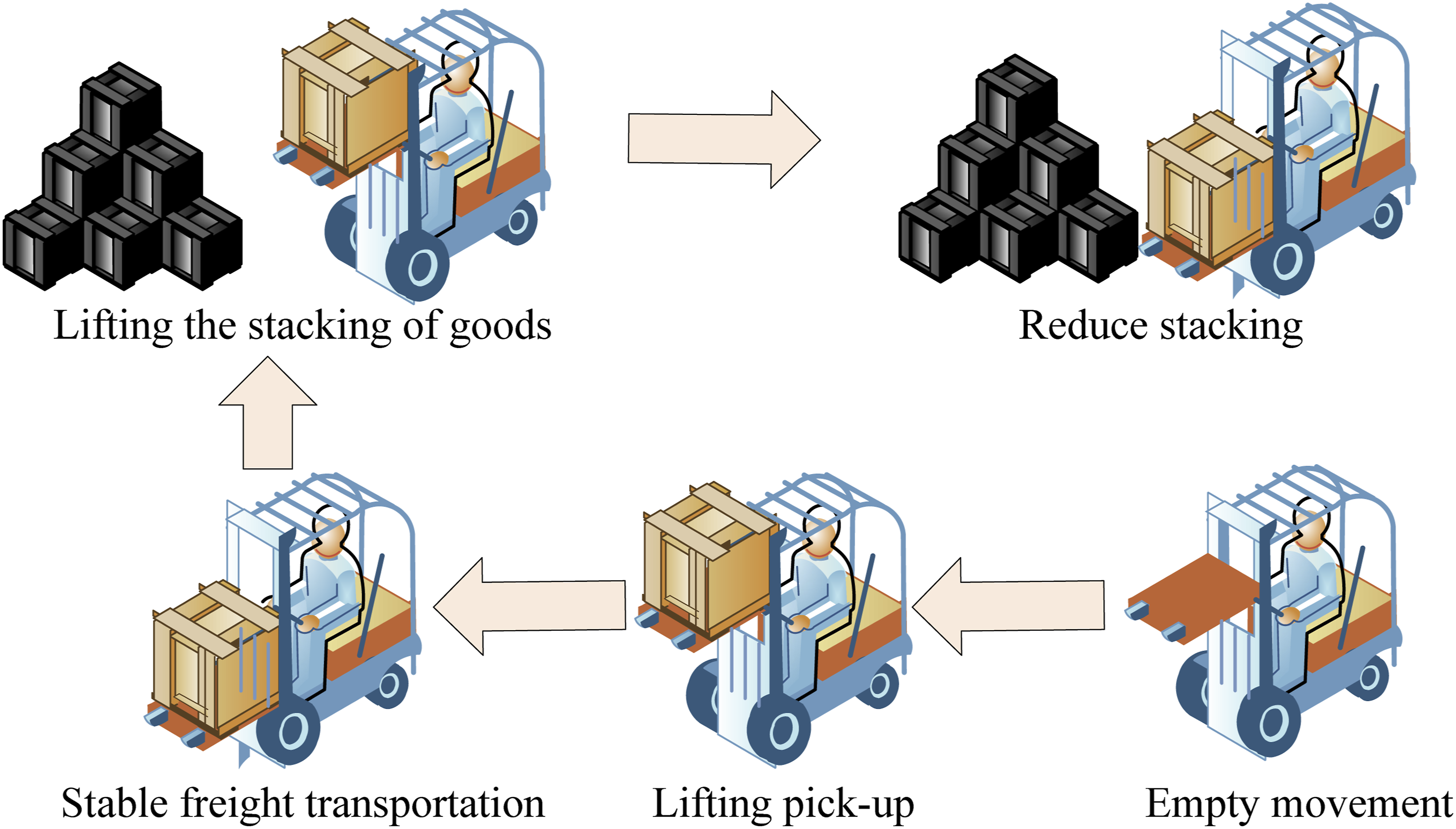
Figure 2 is the design diagram of a FHL system improved based on SR technology. The improved SR FHL system includes five main structures: secondary component, accumulator, overflow valve, one-way valve and engine. When the fork lift truck performs the fork lift operation, the secondary element and accumulator are driven by the engine and start to work. At this time, secondary element 2 performs fork lifting operation, and the accumulator and secondary element 1 can provide energy for secondary element 2, reducing the dependence on the engine. By controlling the energy displacement of the secondary element, the lifting speed of the fork can be controlled at a lower energy consumption loss. When the forklift performs the fork lowering operation, the secondary element 2 starts to turn, and the lifting system starts to fall with the help of the gravity potential energy of the cargo. The secondary element 1, driven by the secondary element 2, provides the recovered gravity potential energy to the energy accumulator, and the falling speed of the fork system can be controlled by the displacement of the secondary element 2.
14
Compared to traditional lifting systems, secondary lifting systems can convert the gravitational potential energy generated by lowering the fork into electrical energy and store it in an energy storage device by switching the motor operating conditions. When the fork rises again, the gravitational potential energy is released to provide power by turning back the motor. Design drawing of FHL system based on SR technology improvement.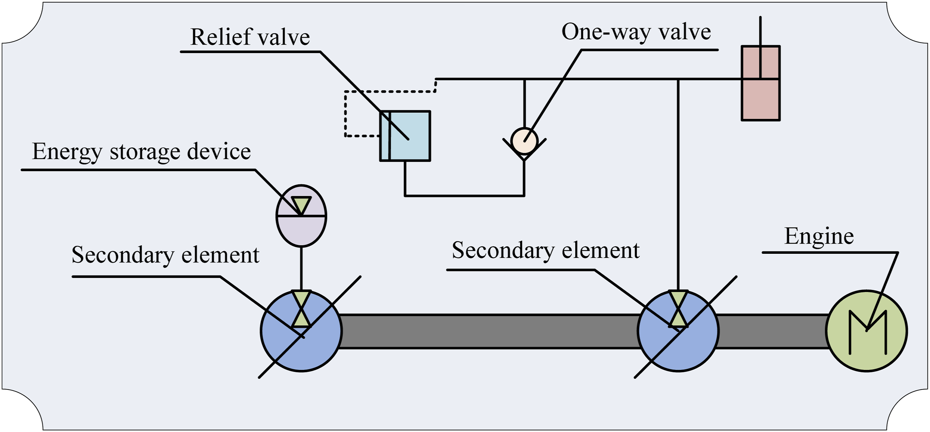
Design parameters of FHL system
To achieve the improvement of the hydraulic lifting system for SR forklifts proposed in section 3.1, this study will explore the design parameters and component selection of the system. First of all, the pump and motor of the secondary element in the system are selected as the symmetrical meshing gear form. The secondary element of this form has the advantages of simple structure and strong pressure bearing ability, and can load goods with high pressure. 15
Figure 3 is a schematic diagram of the lifting system structure. Assuming that the weight of the loaded goods in the lifting system is Schematic diagram of the lifting system structure.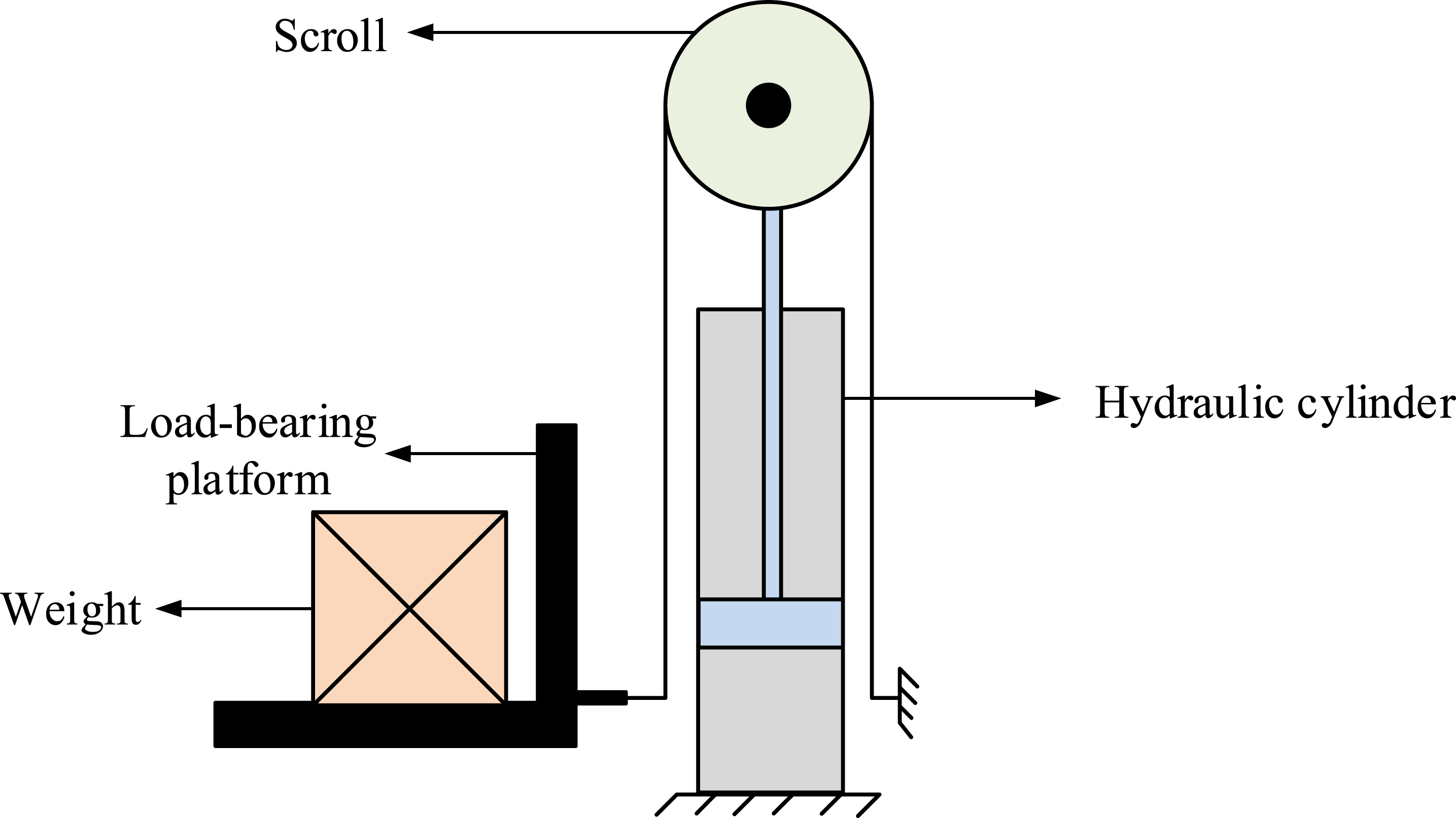

In formula (1),

In formula (2),

In formula (3),

In formula (4),

In formula (5),
Figure 4 shows the pressure volume diagram of the energy storage device. The types of airbag energy storage devices are mainly divided into two parts: oily liquid and gas, and the two parts are isolated by the airbag. When the external pressure increases, the airbag is compressed and oily liquid enters the airbag. When the external pressure decreases, the airbag relaxes and the pressure is released, playing a role in charging and discharging energy. The energy charging and discharging process of the energy accumulator can be divided into isothermal and adiabatic processes according to the temperature change. Wherein, the calculation method of accumulator volume parameter in isothermal process is shown in formula (6). Pressure volume diagram of energy accumulator. (a) Volume pressure curve of airbag energy storage device and (b) schematic diagram of airbag energy storage device operation.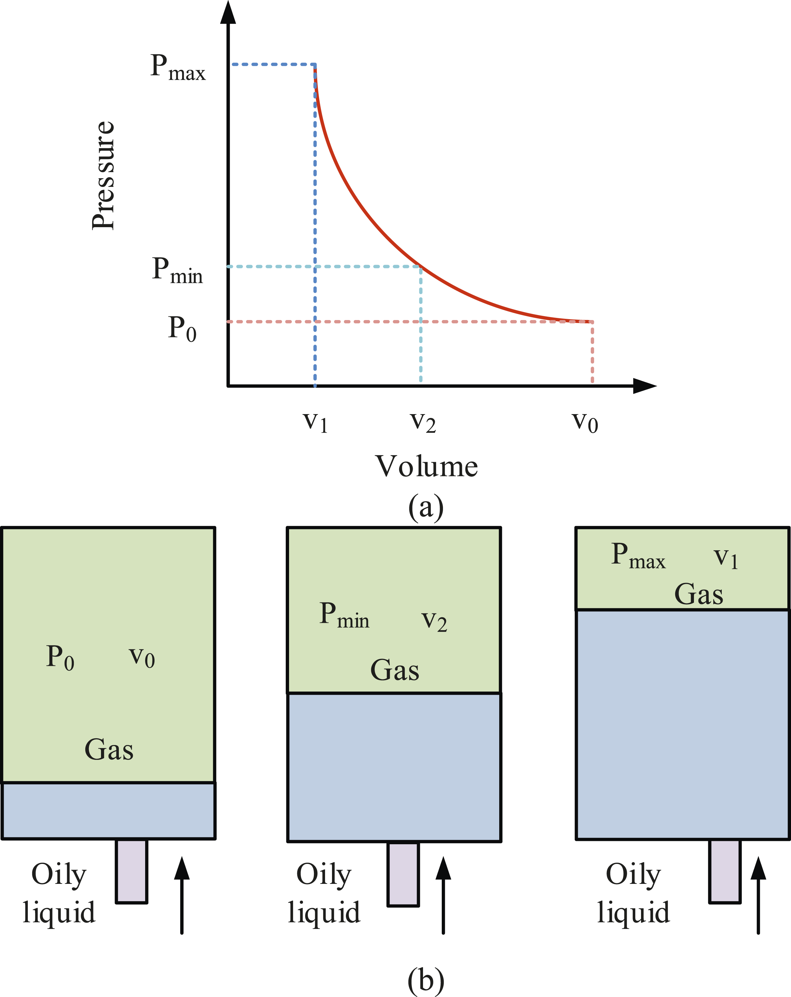

In formula (6),

In formula (7),

Assuming that the energy storage device can complete the charging and discharging of stored energy in an ideal state, the

In formula (9),

At the same time, the energy storage device, as a component for storing energy in the lifting system, will inevitably generate a certain amount of energy loss. The highest proportion of energy loss is thermal energy loss

In equation (11),
Simulation modeling research of FHL system based on AMESim
AMESim is a widely used simulation software, especially in the dynamic design and analysis of forklift hydraulic systems. 18 There are four steps required to build a simulation model using AMESim software. The first step is to create a sketch of the model, in which the main structure and approximate framework of the model need to be drawn. The second step is to select the required sub components in the model and build them according to the design sketch. The third step is to set the model parameters of the sub components. The fourth step is to analyze the simulation model. Because the secondary element pump/motor in the SR FHL system proposed in this study is of great significance, it is necessary to first build the secondary element pump/motor simulation model.
Figure 5 shows the AMESim simulation model of the secondary element pump/motor. When the secondary element is the pump, the control signal of position 6 is negative, control valve 2 is closed, control valve 3 is left, and the hydraulic pump of position 5 outputs oily liquid. When the secondary element is in motor operation, the control signal of position 6 is positive, the control valve of position 2 is in left position, the control valve of position 3 is in state, and the motor of position 1 outputs torque under the external pressure of oily liquid. On the basis of the establishment of the secondary element pump/motor simulation model, the AMESim simulation model of the SR FHL system can be constructed. AMESim simulation model of secondary element pump/motor.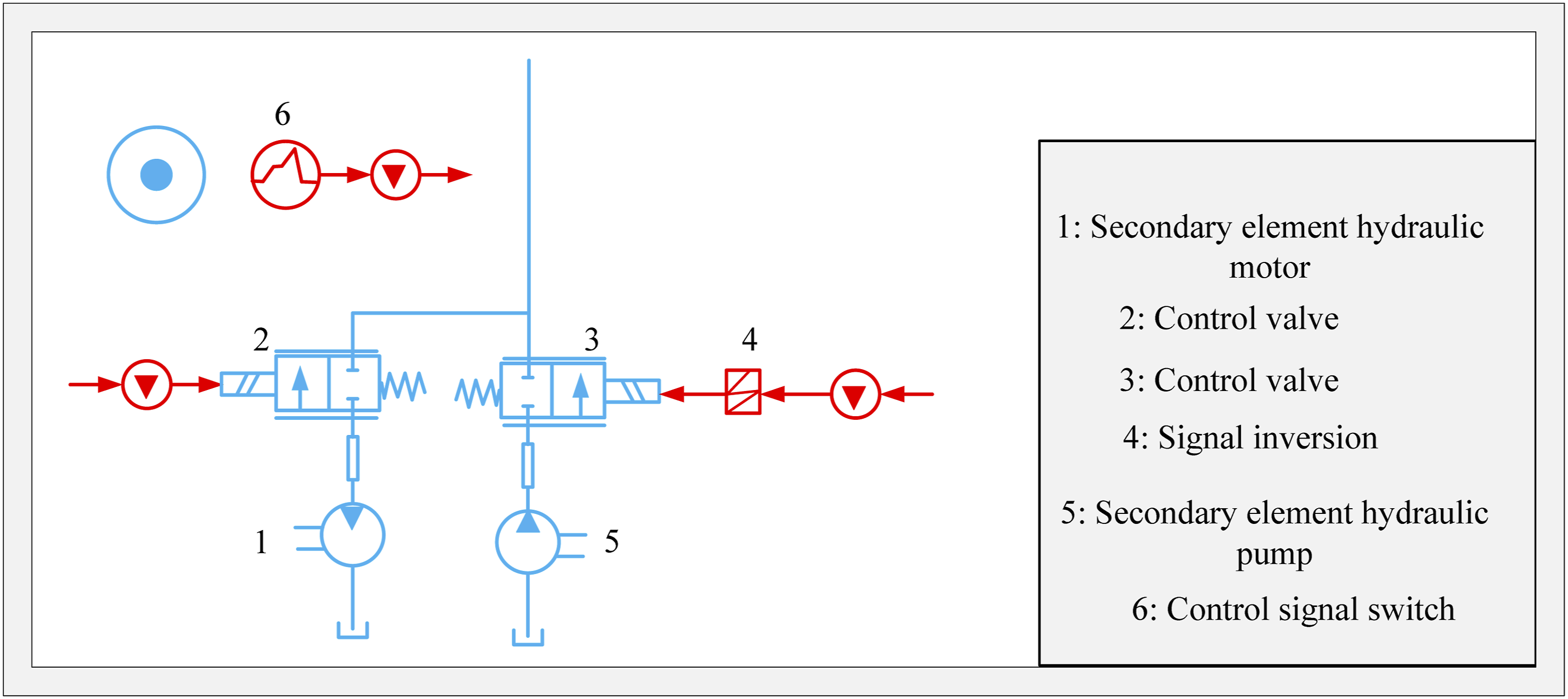
Figure 6 shows the AMESim simulation model of a SR FHL system. When the FHL system is in the lifting state, the secondary element of position 2 is in the pump running state under the action of the control signal of position 6, the secondary element of position 8 is in the motor running state, and position 2 lifts the cylinder of position 3 for liquid supply under the cooperation of the engine of position 1 and the motor of position 8. When the lifting system is in the descending state, under the control signal of position 6, the secondary element of position 2 is in the motor running state, the secondary element of position 8 is in the pump running state, and the pump of position 8 provides hydraulic energy to the accumulator of position 7 with the assistance of the engine of position 1 and the motor of position 2. AMESim simulation model of SR FHL.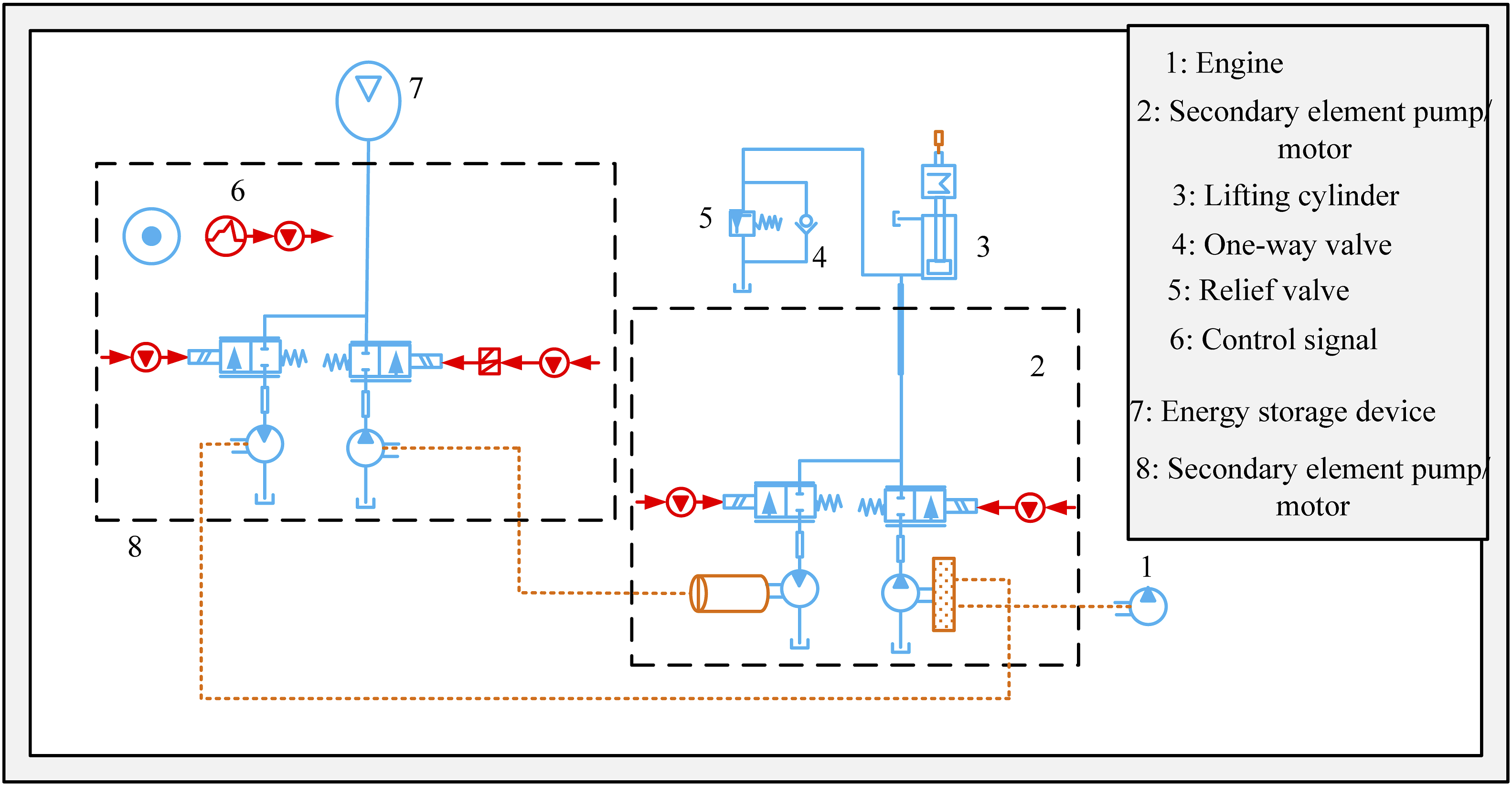
Performance analysis of AMESim simulation model for SR FHL
To improve the energy-saving effect of the FHL system and reduce energy consumption waste, this study adopted SR technology to improve the FHL system, and constructed a simulation model using AMESim software. To explore the improvement effect of the hydraulic lifting system of the SR forklift, this study would analyze the different performance of the model and the factors that affect the energy-saving effect by setting up AMESim simulation experiments.
Optimization performance analysis of SR FHL system
To analyze the performance of the improved SR FHL system, this experiment used the traditional forklift lifting system as a comparison system, and constructed simulation models using AMESim software. The performance comparison analysis was conducted based on the application effects of the two simulation models under different component parameters.
Model parameter table for different lifting systems.
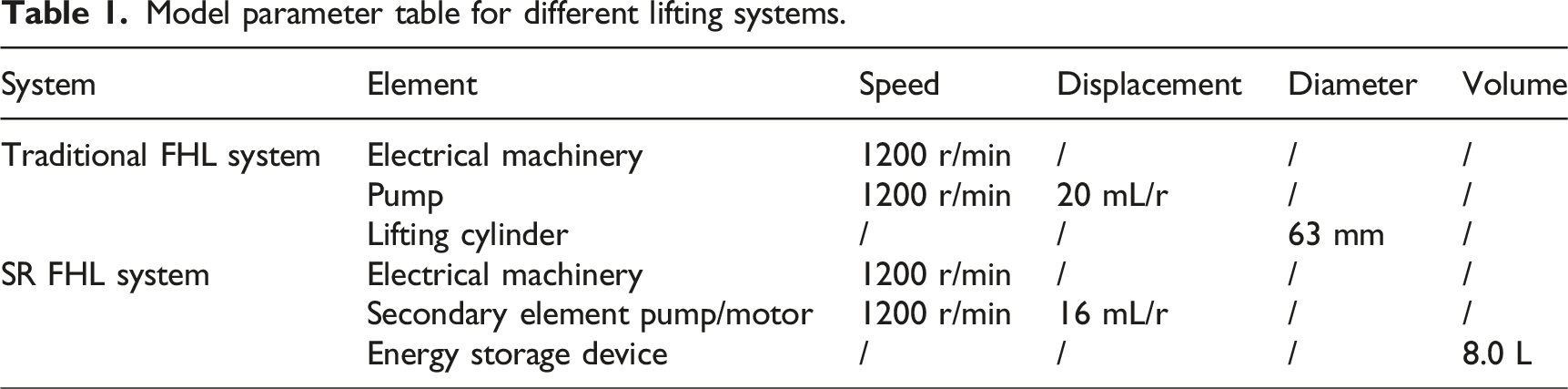
Figure 7 shows the energy consumption comparison curve under different forklift lifting systems. Among them, Figures 7(a) and (b) show the energy consumption changes of traditional forklifts and SR FHL systems, respectively. The energy consumption of the improvement system was mainly divided into two types: busbar and mechanical energy consumption. The final busbar energy consumption of the SR FHL system was 67 kJ, which was lower than the 96 kJ of the traditional lifting system. The mechanical energy consumption of the two lifting systems first increased and then stabilized to 0 over time. The maximum mechanical power consumption achieved by the SR FHL system was 22 kJ, which was lower than the traditional lifting system’s 29 kJ. The SR FHL system can effectively utilize the potential energy of the lowering process to reduce the energy consumption of the lifting system. In summary, the overall energy consumption of the SR FHL system is lower than that of traditional lifting systems. Comparison curves of energy consumption under different lifting systems. (a) Traditional FHL system and (b) SR of FHL system.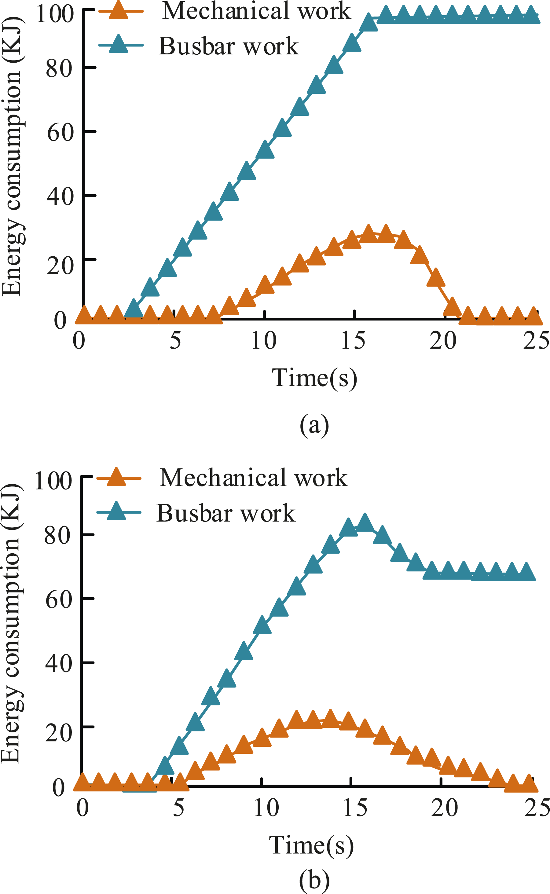
Figure 8 shows the variation curves of speed and pressure difference in different lifting systems. Among them, Figures 8(a) and (b) show the traditional FHL system and the SR FHL system, respectively. In traditional FHL systems, there was a certain dead zone in the adjustment of lifting speed. When the time reached 12 seconds, the speed of the lifting system has basically reached its maximum value, and the system pressure difference has decreased to around 0.5 MPa. Although the pressure difference of the SR FHL system also showed a decrease, it quickly rose again until the lifting speed reached a high level and still maintained a pressure difference of around 4 MPa, increasing the range of speed regulation. Therefore, the SR and improving system had more excellent speed regulation performance. Speed and pressure difference variation curves in different lifting systems. (a) The variable speed performance of traditional FHL system and (b) variable speed performance of SR FHL system.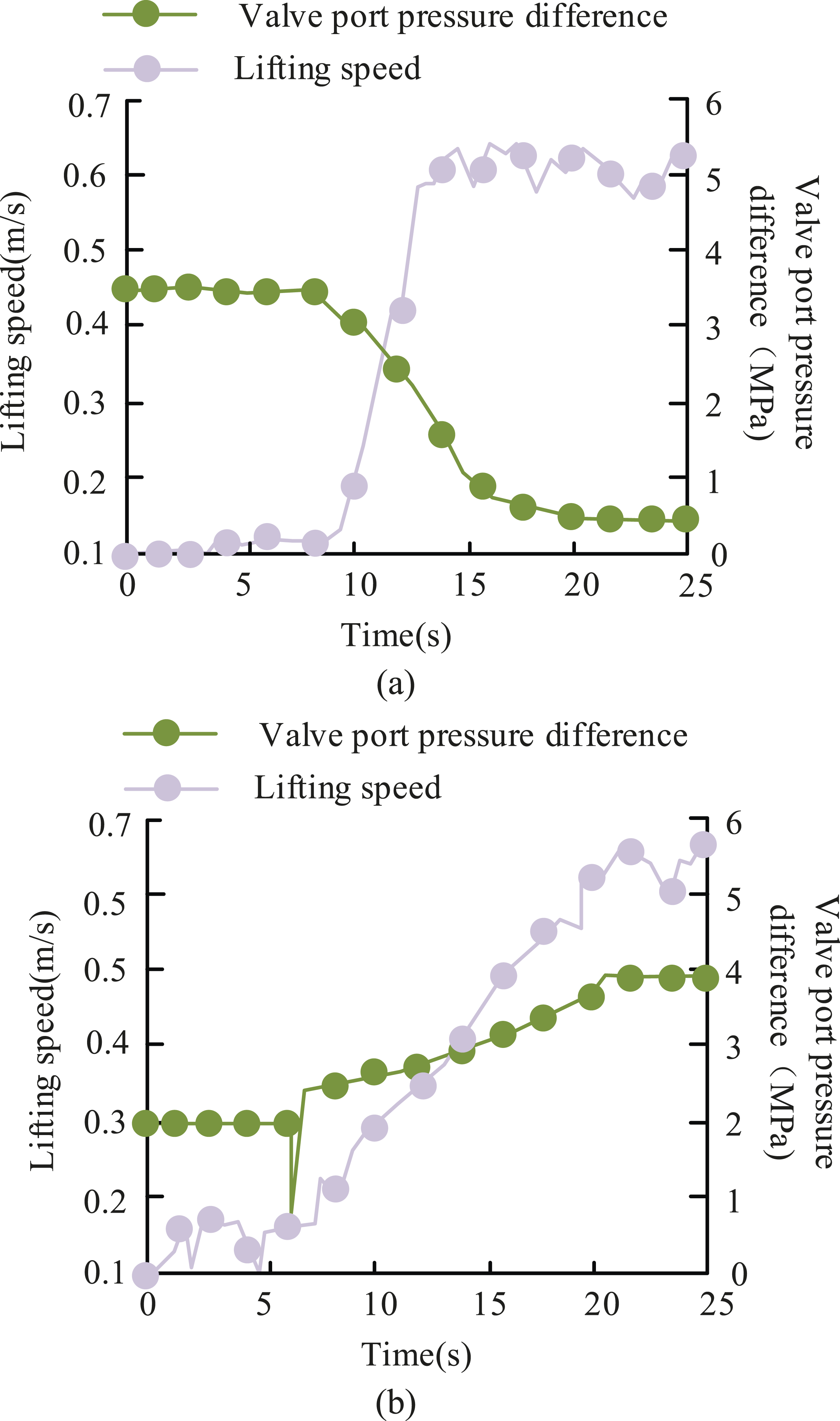
Figure 9 shows the lifting efficiency of different lifting systems under various pump pressures. Among them, Figures 9(a) and (b) show the lifting efficiency of the traditional lifting system and the SR FHL system under different pump pressures, respectively. As the lifting work progressed, under different pump pressures, the efficiency of both lifting systems first increased and then decreased, and the lower the pump pressure, the higher the lifting efficiency. The traditional FHL system could achieve a maximum lifting efficiency of 82.1% when the pump pressure was 0.5 MPa, while the SR FHL system could achieve a maximum lifting efficiency of 87.8% when the pump pressure was 0.5 MPa. In summary, compared to traditional FHL systems, SR FHL systems could achieve higher work efficiency. The pump pressures of the traditional regulation lifting system and the secondary regulation lifting system were set to 0.5 MPa and 0.15 MPa, and the maximum speed was used. Under these conditions, the efficiency and safety of the two systems were analyzed, and the results are shown in Table 2. Lifting efficiency of different lifting systems under various pump pressures. (a) Improving system efficiency of traditional forklifts at different pump speeds and (b) improving system efficiency of SR forklifts at different pump speeds. Comparison of two methods for improving system performance.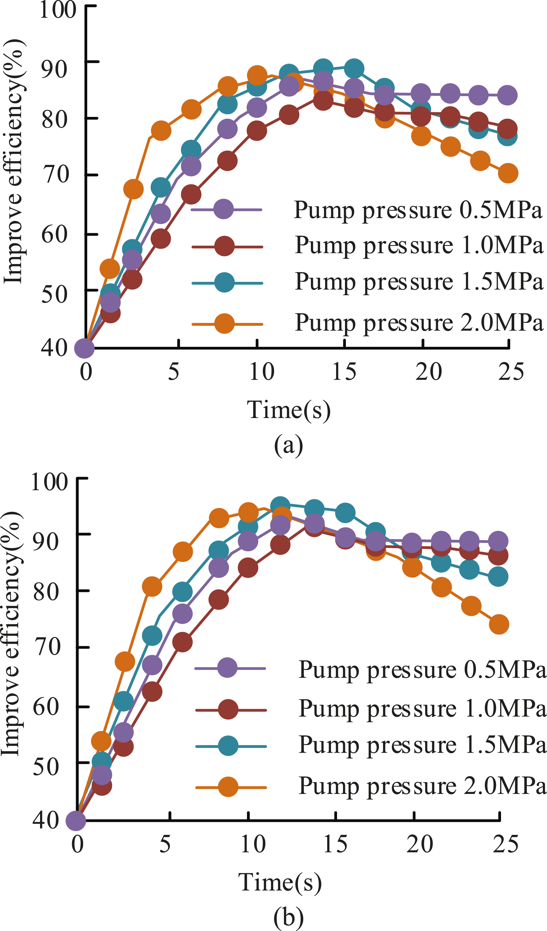

According to Table 2, the efficiency, safety, and energy consumption of the secondary regulation lifting system under pump pressure of 0.5 MPa are 95.2%, 93.3%, and 65.4 kJ, respectively. Under the condition of 1.5 MPa, the efficiency, safety, and energy consumption are 90.1%, 91.8%, and 69.6 kJ, respectively. The experimental results show that the performance, safety, and energy consumption of the secondary regulation improvement system are significantly better than those of the traditional regulation improvement system.
Energy-saving effect analysis of SR FHL system
To verify the impact of different factors in the hydraulic lifting system of a SR forklift on system energy consumption, this study conducted three sets of experiments using the AMESim simulation model of the SR FHL system. The first group was to set the lifting speed to 0.2 m/s and the energy storage capacity to 8.0 L, and compared and analyzed the working curve and energy consumption of the lifting system at loads of 5 kg, 10 kg, and 15 kg, respectively. The second group set the load weight at 10 kg and the energy storage capacity at 8.0 L to analyze the working curve and energy consumption of the lifting system at lifting speeds of 0.1 m/s, 0.2 m/s, and 0.3 m/s, respectively. The third group set the load weight at 10 kg and the lifting speed at 0.2 m/s to analyze the working curve and energy consumption of the lifting system using 5 L, 8 L, and 11 L capacity energy storage capacity. By comparing the working curve and energy consumption changes, it could determine the degree of influence of load weight, lifting speed, and energy storage capacity on system energy consumption.
Figure 10 shows the working curve and energy consumption comparison of the SR FHL system under different load weights. Among them, Figures 10(a) and (b) show the working curves and energy consumption of the lifting system under different loads, respectively. The working path of the motor under different loads was almost the same, but the energy consumption varied greatly. The higher the load, the greater the energy consumption. Because the larger the weight, the higher the gravitational potential energy of the heavy object. The motor needs to provide greater kinetic energy to balance the influence of gravitational potential energy and lift heavy objects. When the load weight was 5 kg and 15 kg, the energy consumption difference between the two was 75 kJ, and the displacement difference was 0 m. Therefore, the load weight factor had a certain degree of impact on energy consumption, and the impact of the working curve could be ignored. Comparison of working curves and energy consumption of SR FHL systems under different load weights. (a) Working curves of SR lifting system under different load weights and (b) energy consumption of SR lifting system under different load weights.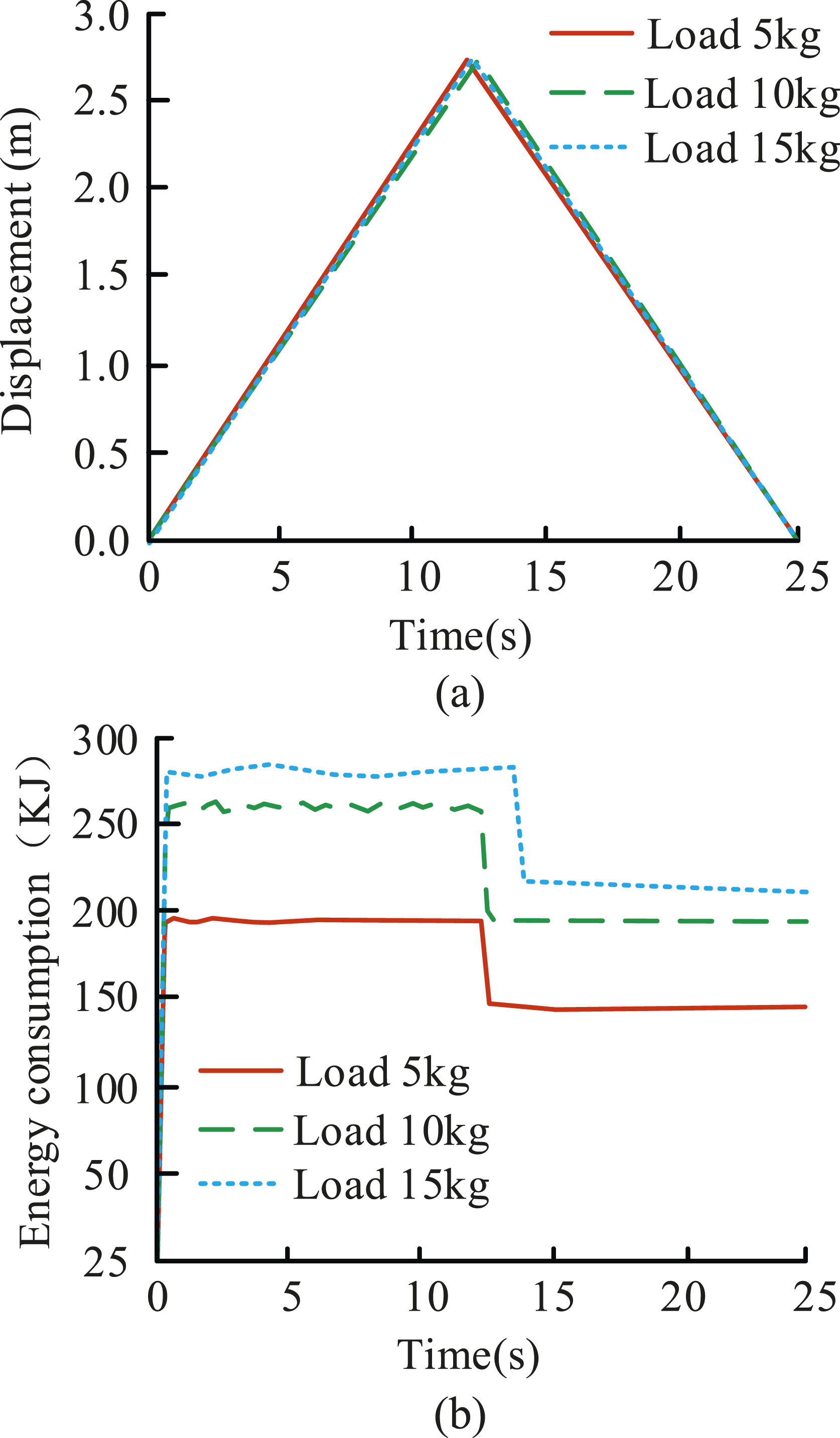
Figure 11 shows the working curve and energy consumption comparison of the SR FHL system under different lifting speeds. Among them, Figures 11(a) and (b) show the working curves and energy consumption of the lifting system under different lifting speeds, respectively. The change in speed had a significant impact on the working curve and energy consumption of the system. Based on the analysis of the working principle of the FHL system, although the motion trend of the working curve was consistent, there was a significant difference in the energy consumption and displacement of the motor at different lifting speeds. Whether it rises or falls, the faster the movement speed, the greater the energy consumption. When the lifting speed was 0.1 m/s and 0.3 m/s, the displacement distance difference between the two was 1.5 m, and the energy consumption difference was 123 kJ. Therefore, the change in lifting speed had a significant impact on the working curve and energy consumption of the SR FHL system. Comparison of the working curve and energy consumption of the SR FHL system under different lifting speeds. (a) Working curves of SR system under different lifting speeds and (b) energy consumption of SR system under different lifting speeds.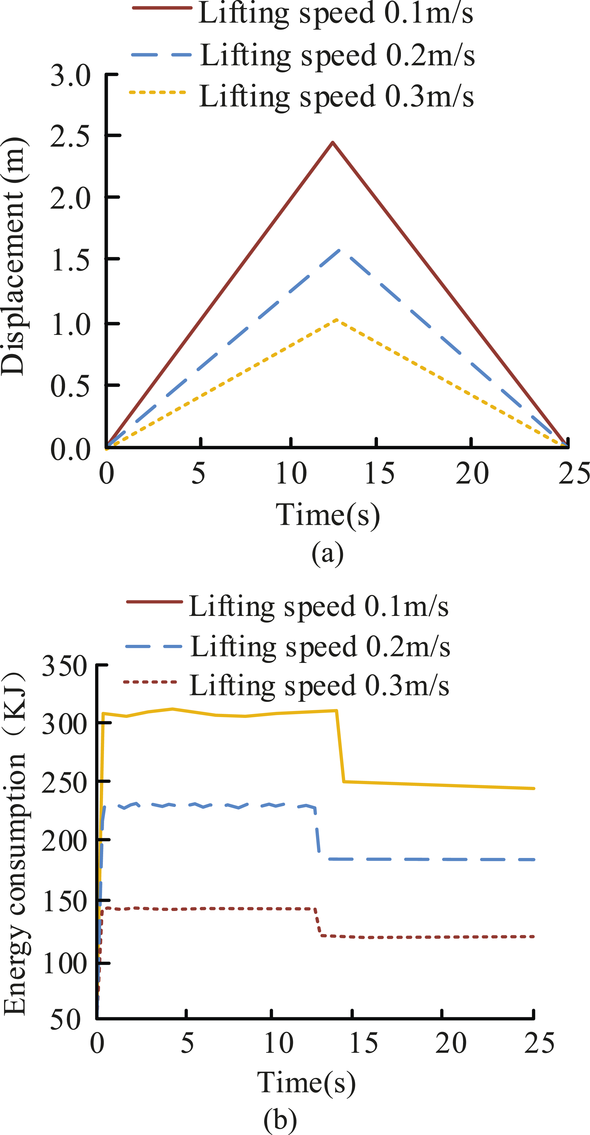
Figure 12 shows the working curves and energy consumption comparison of the SR FHL system under different energy storage capacities. Among them, Figures 12(a) and (b) show the system operating curves and energy consumption when the energy storage capacity was 5 L, 8 L, and 11 L, respectively. When the energy storage capacity was 8 L and 11 L, the trend of energy consumption change was basically consistent, while the energy consumption of the improvement system with a capacity of 5 L was significantly higher than the other two volumes. This was because smaller energy storage capacity would quickly consume the stored energy, thereby increasing the energy consumption of the system. When the energy storage capacity was 5 L and 11 L, the displacement distance difference was 0.1 m, and the energy consumption difference was 89 kJ. Therefore, the change in energy storage capacity had a small impact on the working curve of the SR FHL system and had a certain impact on energy consumption. Comparison of working curves and energy consumption of SR FHL systems under different energy storage capacities. (a) Working curve of SR FHL system under different energy storage capacity and (b) SR to enhance system energy consumption under different energy storage capacities.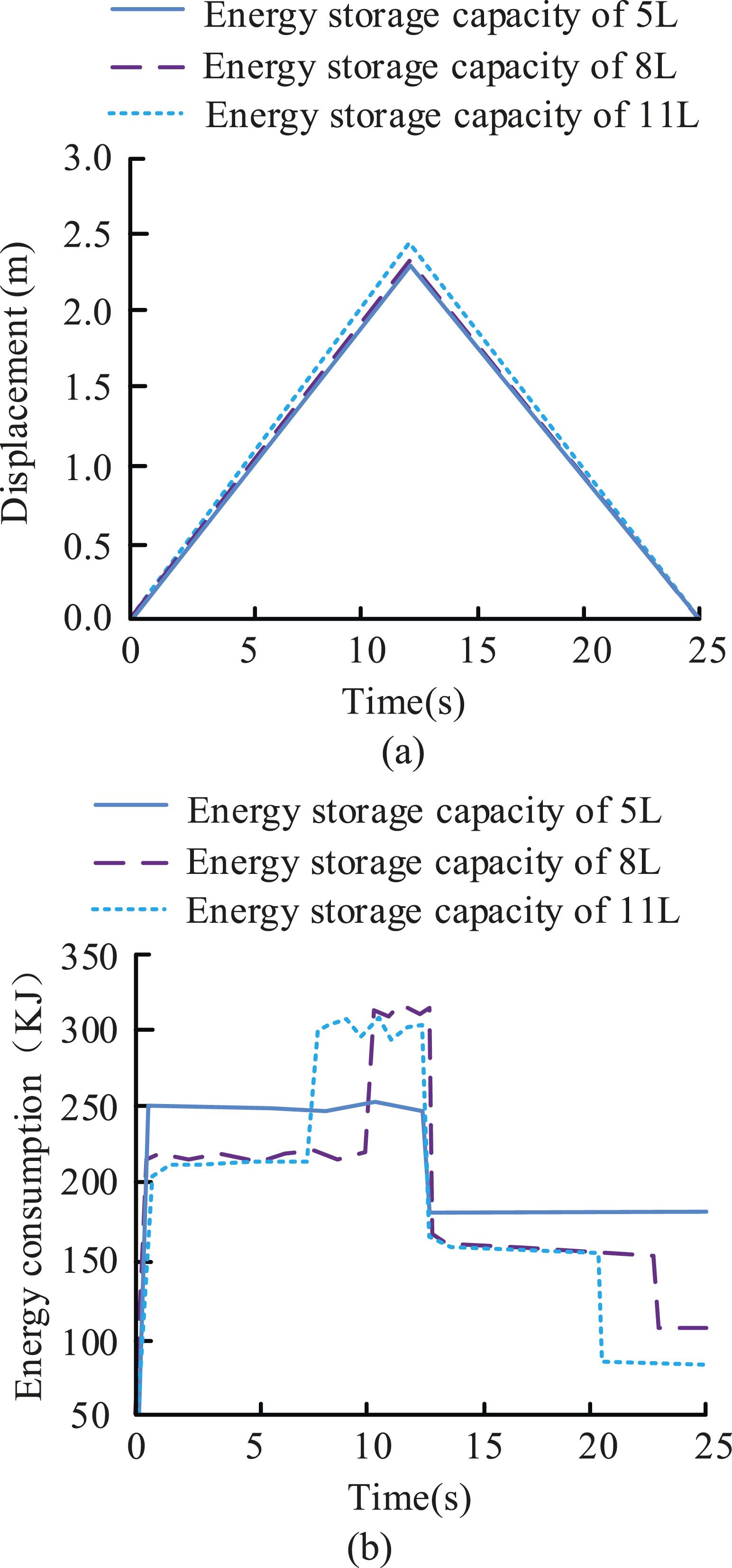
Figure 13 shows the different cost consumption curves for different systems. The energy and labor costs of the SR lifting system were lower than those of traditional FHL systems. The SR lifting system could reduce the energy consumption of the lifting system during operation through energy storage, thereby reducing energy consumption costs. The SR FHL system had faster operational efficiency, as it can complete the improvement work in a shorter time, resulting in lower labor costs. The labor cost of the SR FHL system stopped rising at the 7th hour because the SR FHL system completed the traditional FHL task that required 10 hours within 7 hours. Finally, the labor cost of the SR FHL system within 10 hours was 100 yuan, and the energy consumption cost was 100 yuan. Therefore, the SR FHL system has a more economical application cost. Different cost consumption curves for different systems.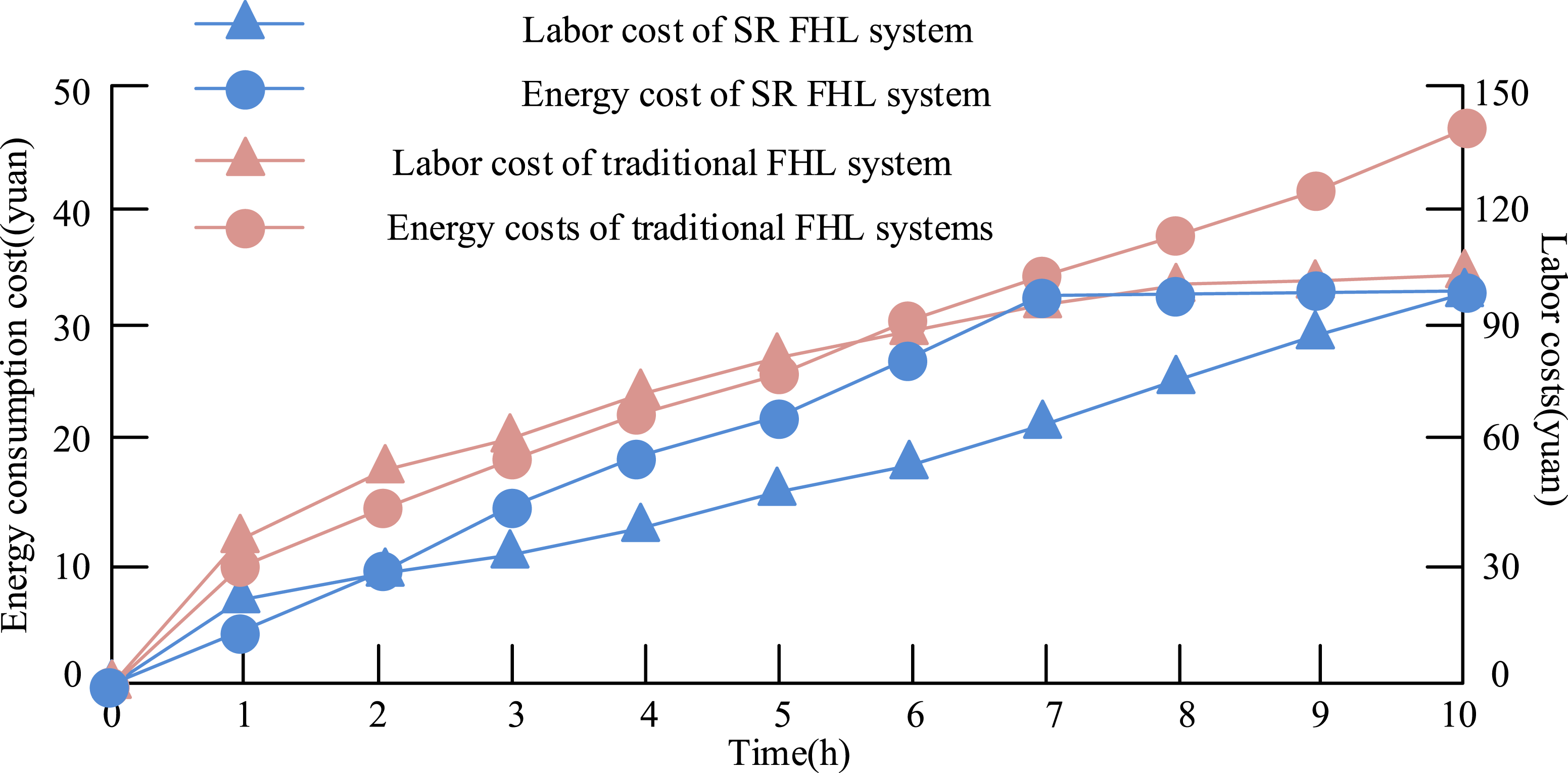
Conclusion
With the increasing demand for energy-saving machinery, forklifts, as commonly used mechanical transportation equipment, have been widely discussed. The traditional FHL system suffered from significant energy consumption due to the lack of energy storage and efficiency overflow issues. To reduce the energy consumption of the FHL system, this research proposed to optimize the FHL system by using the SR technology, which recovered the gravitational potential energy in the system by adding secondary components, and stored it in the storage for subsequent systems to reduce the engine consumption. At the same time, to deeply explore the energy-saving effect of the SR improvement system, this study also designed a simulation model of the system using AMESim software and designed simulation experiments for performance research. The simulation experimental findings denoted that the proposed SR FHL system could reduce energy consumption by 29 kJ and maintained a pressure difference of 4 MPa in the later stage of system operation, achieving an efficiency of 87.8%. At the same time, the load weight, lifting speed, and energy storage capacity of the system all affected the energy consumption of the lifting system to varying degrees. To further optimize the energy-saving performance of the system, further research can be conducted based on in-depth analysis of different influencing factors.
Footnotes
Author contributions
Xuewei Zhou conducted experiments, recorded data, analyzed the results, and wrote a manuscript. Xuewei Zhou agreed to the published version of the manuscript.
Funding
The author received no financial support for the research, authorship, and/or publication of this article.
Declaration of conflicting interests
The author declared no potential conflicts of interest with respect to the research, authorship, and/or publication of this article.