




Abstract
Faced with the rising labor costs and low construction efficiency in the construction and decoration industry, there is an urgent need to introduce automation technology to reform construction methods. Therefore, a flexible macro and micro decoration robot is designed, integrating motion redundancy optimization and active compliance control strategies. The gradient projection method is used to optimize the accuracy of the robot arm’s motion trajectory, while the active supple control is used to improve the wall surface adaptability to enhance the stability and accuracy of the finishing actuator system’s force-position tracking. The results showed that the macro/micro robotic arm was accurate in tracking the position and attitude of the trajectory, with only 0.1° in the β-Euler angle. The joint motion of the robotic arm and the driving speed of the micro robotic arm were maintained within reasonable limits. Under the premise of ensuring accurate force and position tracking as well as system stability, the stiffness coefficient should not exceed 10 to avoid frequent small oscillations during tracking and instability due to excessive stiffness. The redundant motion control algorithm and active compliance controller based on impedance control studied have improved the adaptability and accuracy of the robot arm. The designed method can achieve precise wall finishing control, which makes a significant contribution to improving construction efficiency and quality, as well as ensuring worker safety.
Introduction
In modern society, robots are increasingly taking over traditional physical labor, particularly in the construction industry. These robots not only alleviate significant labor demands but also markedly enhance work efficiency. 1 In the construction sector, wall finishing plays a crucial role, as it not only improves the functional and aesthetic value of buildings, but also contributes to environmental beautification. Traditionally, wall finishing has relied heavily on manual labor, which dominates both the time and cost aspects of construction projects. In contrast, wall finishing robots can result in an estimated 85% reduction in labor costs while boosting productivity by a factor of 10 to 15 times, thereby minimizing time and overall expenditure.2,3 Therefore, using robots for high-quality wall finishing has become increasingly important. Nowadays, wall plasterers not only perform basic finishing tasks, but also supervise automatic coating thickness control and surface treatment. 4 However, despite these technological advancements, wall finishing robots may lack the flexibility of manual labor in adapting to non-standard wall surfaces or specialized finish designs. In some older buildings or unique projects, the integration of new technologies with existing processes can encounter challenges related to technology adaptation and system compatibility. 5 Therefore, faced with challenges such as rising labor costs, low construction efficiency, and difficulty in meeting increasingly complex design requirements in the building decoration industry, a new type of decoration robot is designed, which combines macro robotic arm and micro robotic arm and a 3-RPS parallel mechanism. The kinematics of the arm is analyzed using gradient projection method, and a redundant motion solving algorithm is proposed to construct a robot arm controller. An impedance control strategy combined with an improved Proportional-Integral-Derivative (PID) controller is adopted to realize soft contact with the wall surface. The research aims to speed up the wall treatment and shorten the project cycle through the interior wall finishing design model, providing a scientific theoretical basis for improving the technical level of the construction industry. The key contribution of the research lies in designing a composite robot system that integrates macro and micro robotic arms. This system can not only perform basic operations such as wall finishing, but also has adaptive functions to cope with non-standard and complex wall environments. By introducing an active compliance control algorithm and precisely adjusting the contact force and motion state, the adaptability between the robot and the wall surface is ensured, thereby enhancing the quality and safety of finishing operations.
The research content is mainly divided into four sections. The first section is a literature review, which examines the current research status and existing deficiencies of wall decoration robots. The second section elaborates on the construction method of motion redundancy optimization and active compliance control algorithms for interior wall decoration design models. The third section verifies the validity and practicability of the proposed model through experimental analysis. Finally, the fourth section summarizes the research conclusions and proposes the directions for future research. By systematically elaborating on these contents, readers can gain a comprehensive understanding of the background, methods, and potential applications of this study in the architectural decoration industry.
Literature review
Since the birth of robotics technology, its continuous progress has made many research institutions and companies realize the enormous potential of introducing it into construction. For example, Wang et al. proposed an interactive, immersive process-level digital twin for virtual reality environments. The system incorporated visualization and monitoring, task planning and execution, and interactive communication with a robot. The main responsibilities of robots included sensing and monitoring the work area, precise motion planning, and actual work. After a brief training, users could effectively organize job steps, select the best task plan, and guide the robot’s trajectory. 6 Garrido et al. designed a new wall-climbing inspection robot, which utilized adsorption forces generated by permanent magnets to attach to rebar to facilitate safety-critical concrete structures for climbing. To ensure that the robot operates efficiently on re-bars with different arrangement patterns and on surfaces covered with a protective layer of 30 to 35 mm concrete, simulations and field tests were conducted to determine the optimal configuration of flux-focused permanent magnets. 7 Kim et al. innovatively combined building information modeling techniques with robotic task planning to generate a detailed for executing robot action sequences. The research revealed how BIM technology could be utilized to integrate the fields of architecture and robotics to plan and guide automated robotic operations in construction projects. 8 Liang et al. proposed a new classification method for collaborative human-robot work in construction teams. The classification was based on the robot’s ability to operate independently and the corresponding amount of work required by the human team members. The classification method provided new research paths and ideas for subsequent research. 9
Kulkarni et al. designed a highly automated robotic device specifically constructed to perform wall painting operations. When the robot was activated, it utilized an in-built vertical movement system to carefully paint in the vertical direction starting from the bottom of the wall. Once painting was completed in a vertical area, the robot moved laterally to the next untreated area and continued to perform the painting job. Repeating this process until all walls were evenly painted. The entire wall could be automatically painted. 10 Hartmann et al. proposed a new planning system that parallelized complex tasks and motion planning by decomposing them into multiple small-scale sub-problems. The system combined optimization techniques and sampling-based bi-directional spatio-temporal path planning techniques to efficiently handle multi-robot cooperative operations with uncertain arrival times. The planning system demonstrated excellent robustness in long-term planning and scalability in handling multiple objects and agents. 11 Cai et al. proposed a novel robot path planning strategy that combined deep reinforcement learning with construction worker motion prediction to promote efficient and safe human-machine collaboration in construction scenarios. The research results showed that the robot reached the specified destination with a 100% success rate in a near shortest path. 12 Yu et al. developed an integrated indicator to characterize the receiver’s grip state, including grip strength, posture, and full tactile sensing of the hand. The system was designed to simulate human grip movements and apply it to robotics. It was experimentally validated that this method was superior to techniques that relied on a single perspective to simulate the natural handover of objects during the transfer process from robots to humans, thereby improving the safety of workers when transferring materials at close range. 13
In summary, the research and application of decorative robots mostly focus on specific processes with a single function. The working environment is usually a constantly changing non-standardized environment, but most of the existing robots are tested under ideal conditions in the laboratory, and there are adaptability problems when facing the complex real environment. Most remodeling robots still require human involvement to operate, and are also not sufficient to replace humans in delicate operations. The construction quality of robots cannot catch up with manual construction, and usually can only complete tasks with lower quality requirements. To address the above problems, a design model for interior wall decoration with motion redundancy optimization and active compliance control algorithm is proposed.
Model design of interior wall finishing design incorporating motion redundancy optimization and active supple control algorithm
Design of indoor wall finishing robotic arm based on motion redundancy control algorithm
Macro-motion robots usually refer to robots with a large range of motion and strong power output. They can perform large-scale, high-speed movements and can be used for industrial production, logistics and handling, construction, and more. By precise control and powerful load capacity, various complex tasks can be completed to improve production efficiency and quality.
14
Robotic arms need to meet deadweight and load requirements, and have sufficient travel, compact shape, and sensitive response. Based on these functional requirements, the structure of the micro robotic arm adopts a direct drive parallel mechanism, which is configured as a 3-RPS parallel mechanism, as shown in Figure 1.
15
Structure and coordinate system of 3-RPS parallel mechanism.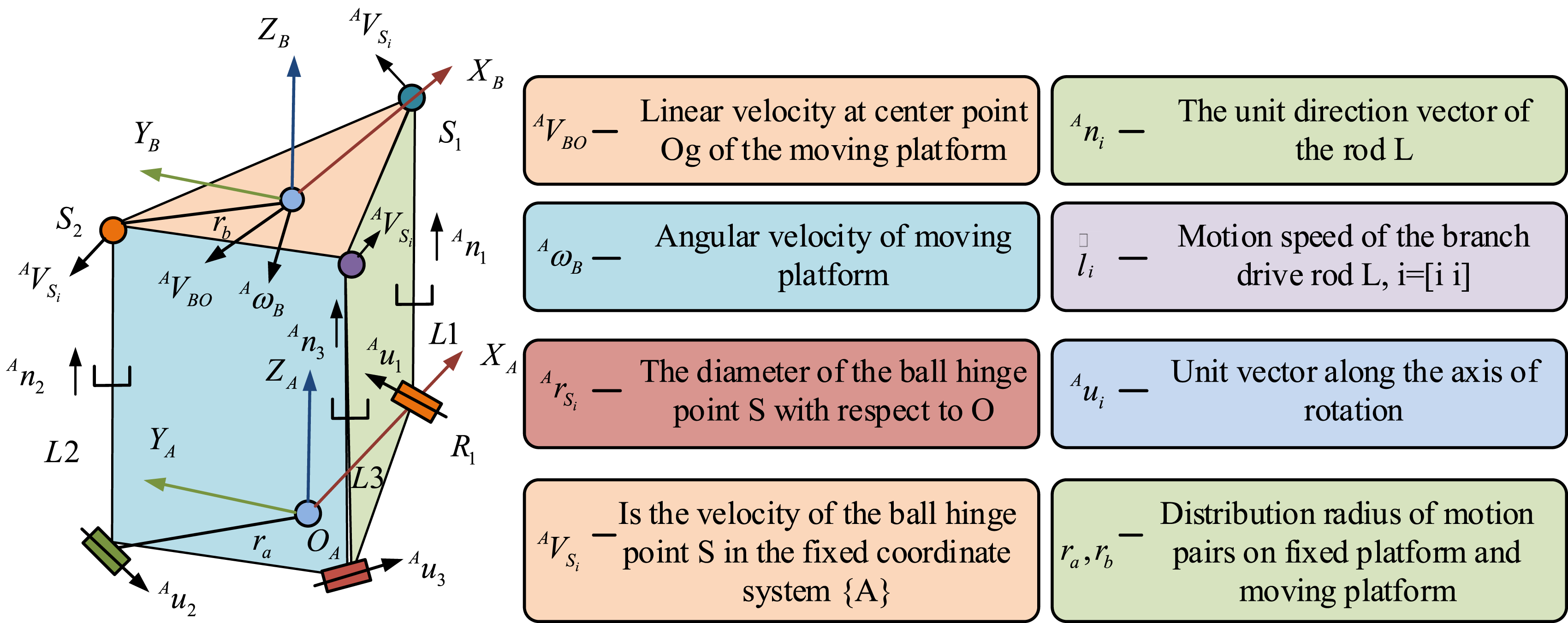
Figure 1 illustrates the structure and coordinate system of the 3-RPS type parallel mechanism. The center point Og of the moving platform has linear and angular velocities, the rod has directional unit vectors, and the branching drives the rod to move at speed i. The parts are connected by ball hinges and their positions have corresponding velocities in a fixed coordinate system. The mechanism is chosen as a form of micro robotic arm structure, because it can meet the similar wrist adjustment attitude similar to that of the micro robotic arm in wall operations. 3-RPS type parallel mechanism has two rotational degrees of freedom, which facilitates the fast and accurate attitude adjustment. Meanwhile, it meets the functional requirements on self-weight and load, travel, compactness, and response speed. The matrix is shown in equation (1).

The expression for the fixed coordinate system


For a 3-RPS mechanism, its workspace is the set of attitude angles that can be achieved by translating the moving platform along the Z-axis. For the 3-RPS mechanism, its workspace is solved with the help of MATLAB programming and the optimization design is carried out.16–18 The distribution of the joint coordinate system of the macro robotic arm is shown in Figure 2. Distribution of joint coordinate system of macro robotic arm.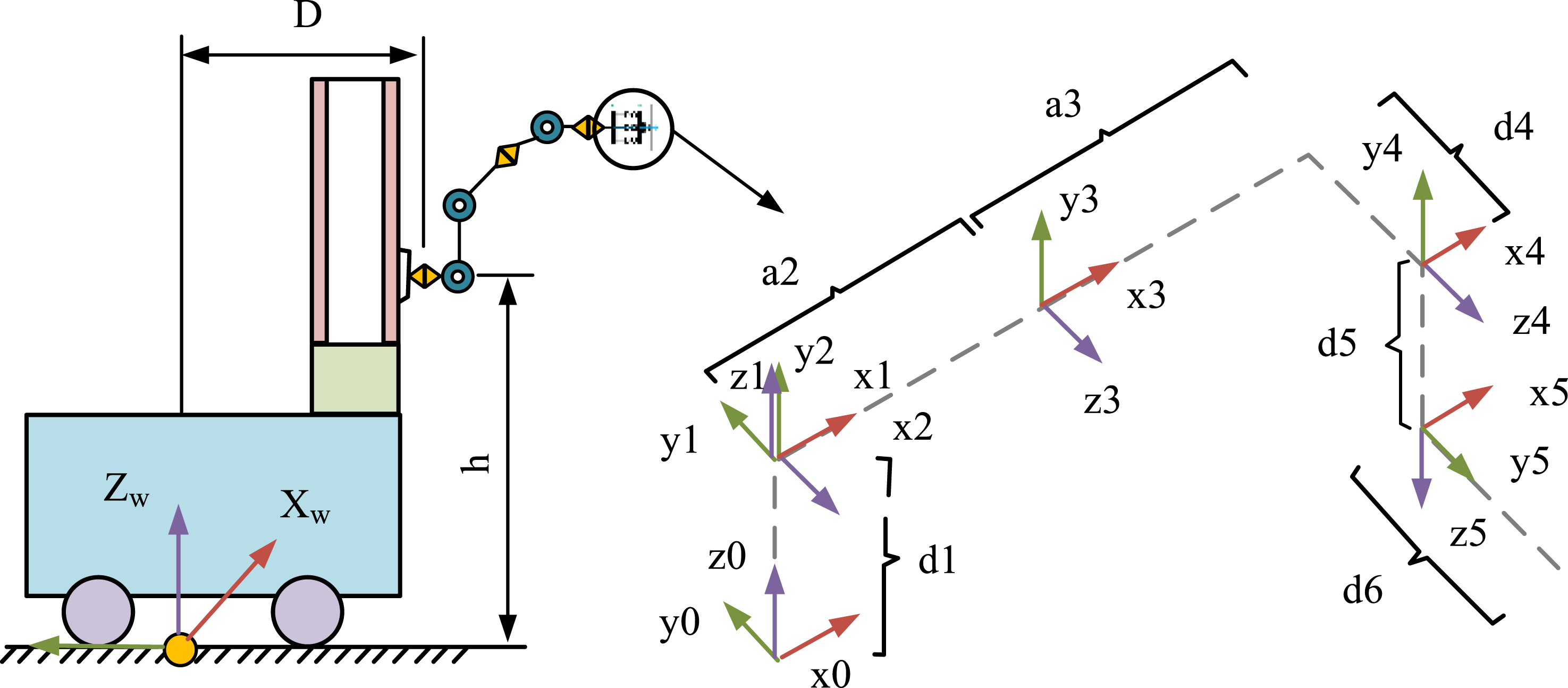
It is assumed that the Jacobi matrix of the macro/micro robotic arm as a whole is shown in equation (4).19,20







The joint optimization is to minimize the objective value in equation (10). Considering the property that the joints of the micro robotic arm have limited motion, the arm will select different Redundant motion simulator for macro/micro robotic arm of decoration robot.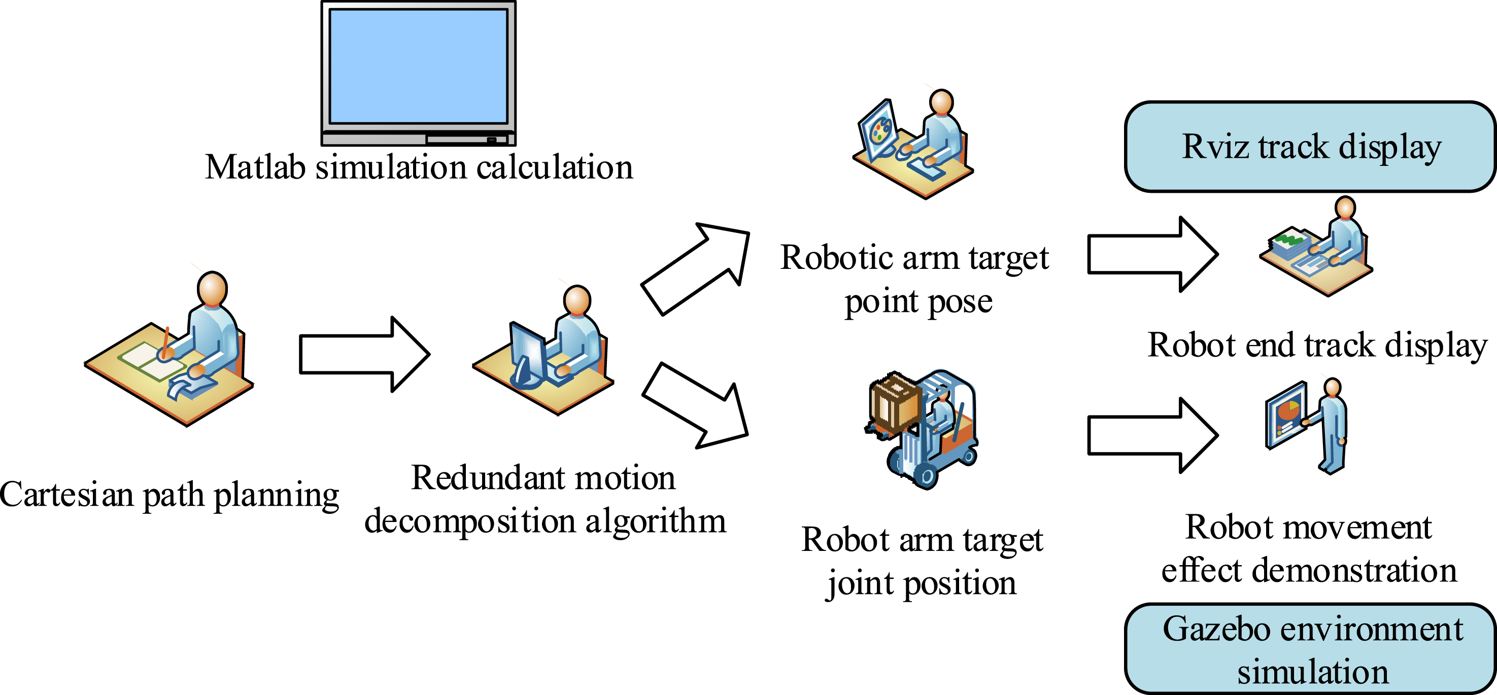

Construction of interior wall finishing model incorporating active active compliance control algorithm
There are two implementation methods for robot active compliance control. One is passive compliance control, and the other is active compliance control.
23
Active pliable control focuses on the force-position relationship, which is categorized into four strategies: impedance control, force/position hybrid, adaptive control, and intelligent control. The latter two are based on the combination of traditional force control theory and advanced control theory. Electrical impedance describes the ratio of voltage to current, and robot impedance control follows this ratio to regulate the ratio of contact force to position for detailed control. The robot can be simplified as a single-degree-of-freedom system. The impedance is expressed by the second-order dynamics equations of the Relation model of impedance and admittance between robot and environment. (a) Impedance relation model (b) Admittance relation model.


In Figure 4(a), Flow chart of pliable control strategy of finishing actuator system.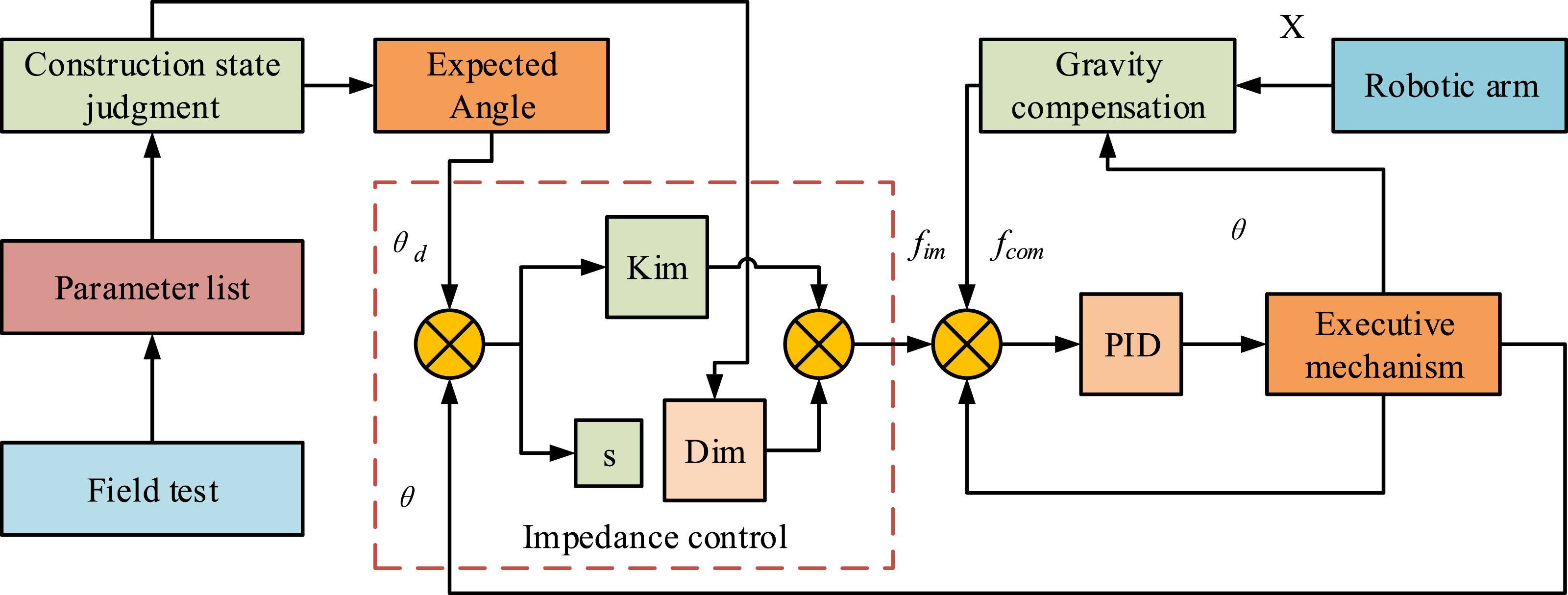
The compliance control strategy flow of the finishing actuator system shown in Figure 5 focuses on collecting data from force sensors to achieve soft contact between the system and the wall. During the finishing operation, the force sensor collects the contact force data between the finishing actuator and the wall surface in real time and inputs it to the system controller. After receiving the data, the system controller is processed by internal arithmetic and outputs an angular displacement instruction. This instruction is used to drive the actuator action so that the actuator can make adaptive adjustment according to the actual situation of the wall surface and realize the soft contact with the wall surface. In this process, the system selects the active compliance control system composed of impedance controller and improved PID controller. The improved PID control introduces the integral separation mechanism to suppress the oscillation in the steady state phase. With such a control strategy, the system can precisely regulate the contact state between the finishing actuator and the wall surface to ensure stable and precise finishing operations under different wall conditions and improve the quality and efficiency of finishing. The control rate of the conventional incremental PID controller is shown in equation (14).



The basic principle of impedance control for plaster actuator in the study is shown in equation (17).


The control output calculation process is shown in equation (19). Macro/micro robotic arm decoration structure.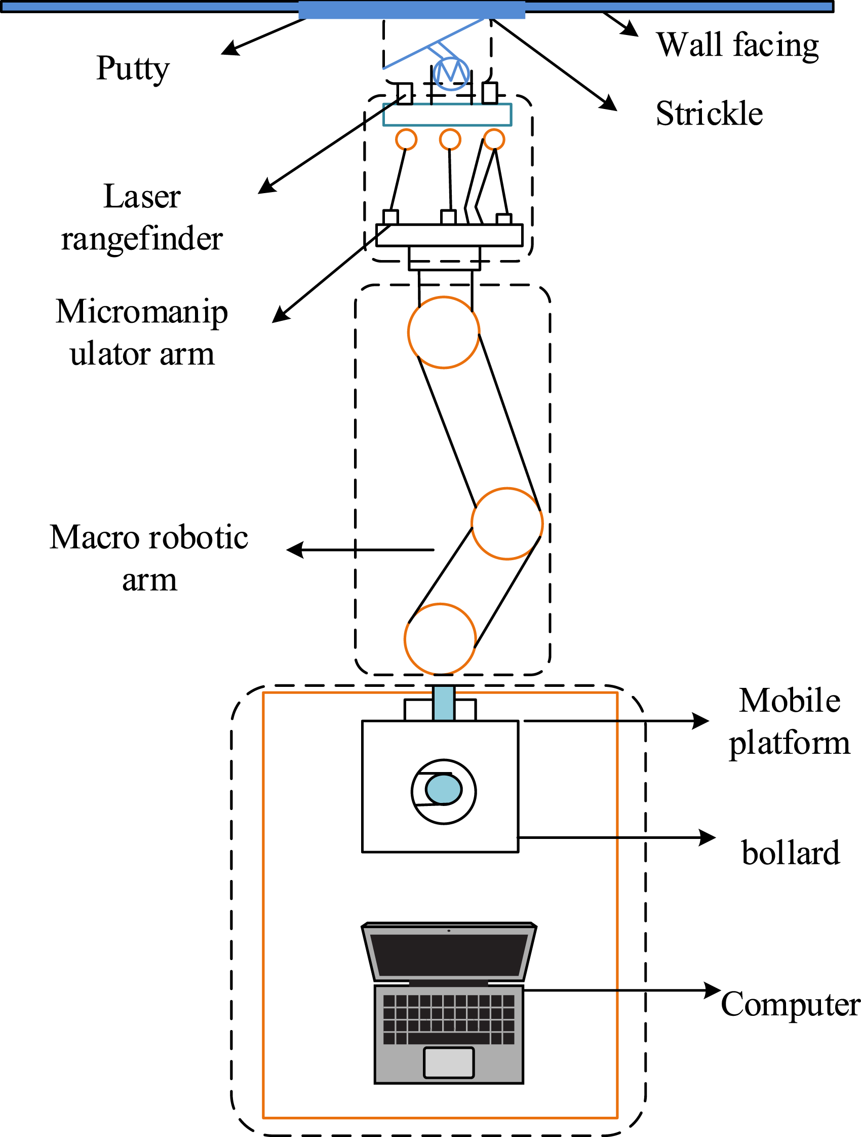

In Figure 6, this interior wall finishing model is divided into four main parts, that is, mobile platform, macro robotic arm, micro robotic arm, and finishing actuator. The mobile platform is configured with a height-adjustable system, which enables the mounted robotic arm to perform high level operations. The arm used is a lightweight UR5 six-degree-of-freedom collaborative robotic arm with a weight capacity of 5 kg, an arm span of 0.85 m, and a joint rotation speed of up to +180 9% s, which makes it suitable for finishing operations that require flexibility in spatial movement. In addition, a small parallel arm with three-degree-of-freedom is developed, capable of lifting at least 2 kg and incorporated with a laser distance sensor to accurately control the position of the finishing scraper. The finishing actuator consists of a servomotor, a speed reducer, a torque sensor, and a stainless steel scraper.
Experimental analysis of the wall finishing model of the decoration robot
Simulation performance verification of decorative robots
D-H parameters of macro robotic arm.
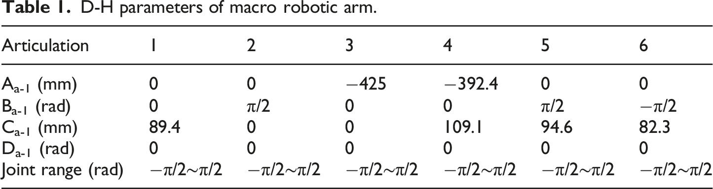
In Table 1, there are several key variables to be clarified when describing the kinematic parameters of the robot arm. i denotes the i-th joint of the robotic arm. Aa-1 and Ba-1 correspond to the spatial distance and rotation angle between the Z-axis of the coordinate system of joint i-1 and the Z-axis of the coordinate system of joint i, respectively. Ca-1 refers to the distance between the origin of the coordinate system of joint i-1 and the origin of the coordinate system of joint i in the direction of Zi-1 axis. As for Da-1, it is the rotation angle of joint i-1 around the Z-axis of its own coordinate system. The study is calculated by MATLAB theory to obtain the macro/micro robotic arm trajectory tracking position and tracking attitude accuracy results.
From Figure 7(a), the calculated results of the trajectory tracking position of the macro/micro robotic arm in the X, Y, and Z-axis had almost no deviation from the actual position. From Figure 7(b), the actual and calculated values of the trajectory tracking attitude of the macro/micro robotic arm had no deviation in the α-Euler angle and γ-Euler angle. Only at the β-Euler angle, there was a deviation of approximately 0.1° between the actual trajectory tracking attitude value and the computer value displayed. In summary, the trajectory tracking accuracy of the macro/micro robotic arm is within the allowable error range. Figure 8 shows the redundant motion simulation results of the macro/micro robotic arm. Macro/micro robotic arm trajectory tracking position and attitude accuracy. (a) Macro/micromanipulator arm trajectory tracking position accuracy (b) Macro/micromanipulator arm tracking attitude accuracy. Simulation results of redundant motion of macro/micro robotic arm. (a) The length of the driving rod of the micromanipulator arm/ the change of the joint Angle of the macro manipulator arm (b) Micromanipulator drive speed.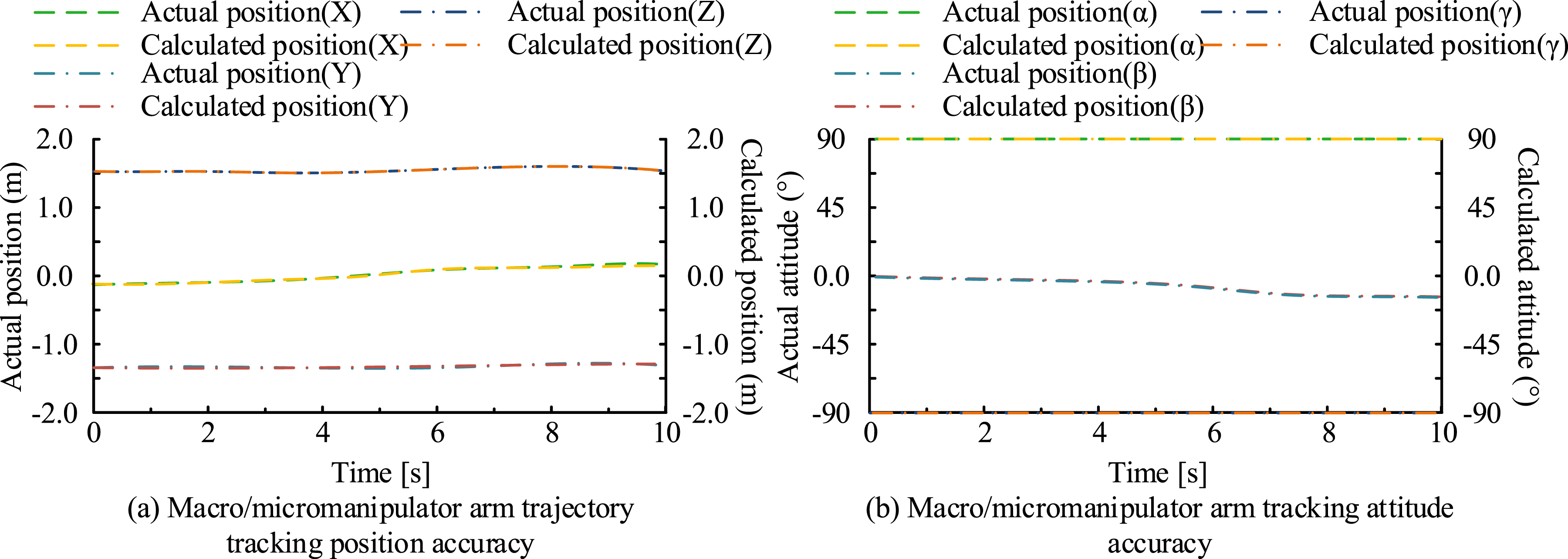
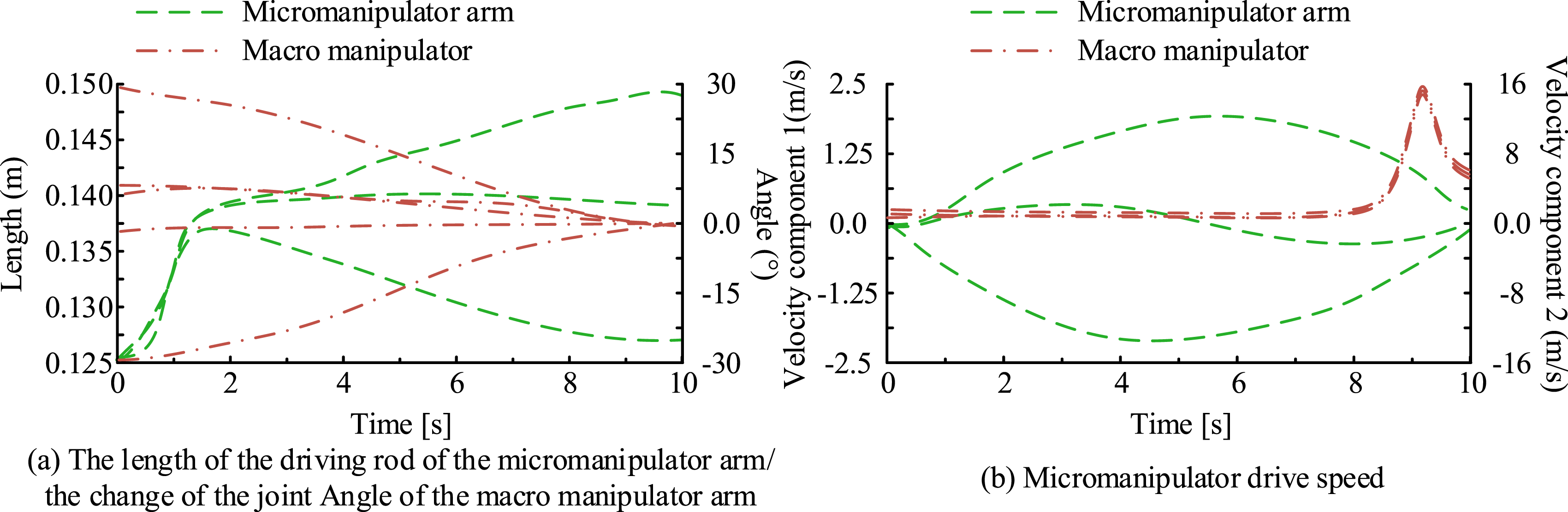
Figure 8(a) shows the relationship between the length of the driving rod of the micromanipulator arm and the joint angle of the macro robotic arm over time. The length of the driving rod of the micro robotic arm fluctuated between 0.125 m and 0.150 m over time, while the joint angle of the macro robotic arm showed a decreasing trend. Figure 8(b) depicts the drive velocity components of the micro robotic arm, including the v component and the ω component. v component fluctuated between −30 and 30, while the ω component fluctuated between −15 and 15. These data indicate that the joint motion and drive speed are within reasonable ranges, and effective limiting and speed limiting are realized. By coordinating the macro robotic arm, the system is able to move in a wide area of space without affecting the precise attitude control of the robotic arm’s end effector. The micro robotic arm is able to synchronize the attitude adjustment when the macro robotic arm moves horizontally along the wall, thus realizing complex motion decomposition and obstacle avoidance adjustment, and ensuring the efficiency and accuracy of the overall system. Figure 9 shows the results of the position response to the external contact force under different K values. Response of positions to external contact forces under different K values. (a) K=1 (b) K=2 (c) K=50.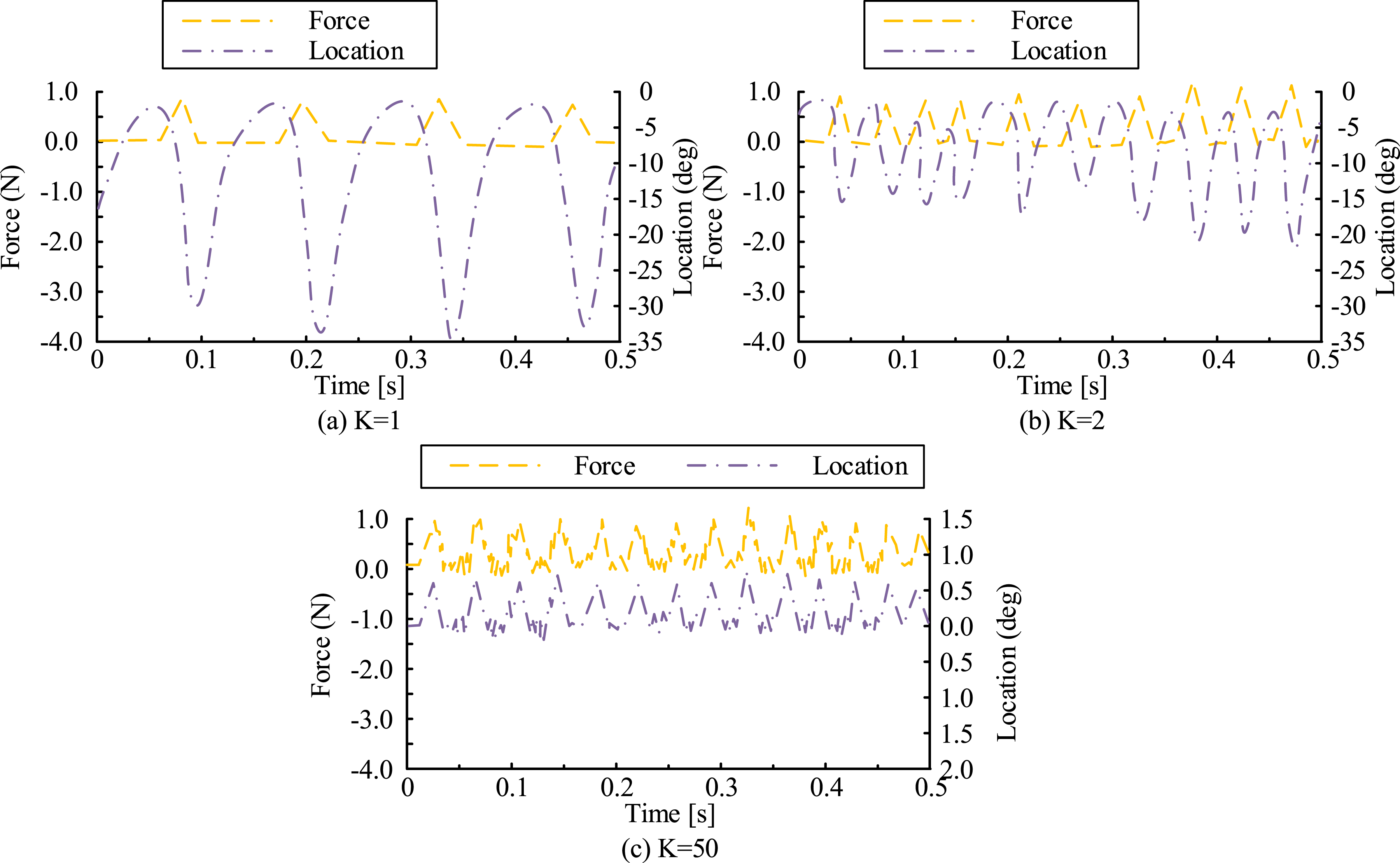
As shown in Figure 9(a) and (b), the flexibility of the system could be effectively changed by adjusting the stiffness coefficient under a consistent external force. In the plaster actuator system, the flexibility was inversely proportional to the stiffness coefficient, that is, the lower the stiffness coefficient, the higher the flexibility of the system. According to Figure 9(c), when K = 50, there was a clear oscillation in the position curve. This oscillation persists on the time axis, indicating that the system is unable to maintain stability even after it enters the steady state, which is a typical manifestation of too high stiffness coefficient leading to excessive rigidity of the system and difficulty in adapting to changes in external forces. Too high stiffness coefficient will destroy the force-position synergistic relationship, so that the positional response cannot precisely follow the change of the external force, which weakens the stability of the system. The tracking results of the system to the external force under different k values are shown in Figure 10. The system’s tracking of external forces under different k values. (a) K=1 (b) K=2 (c) K=10 (d) K=50.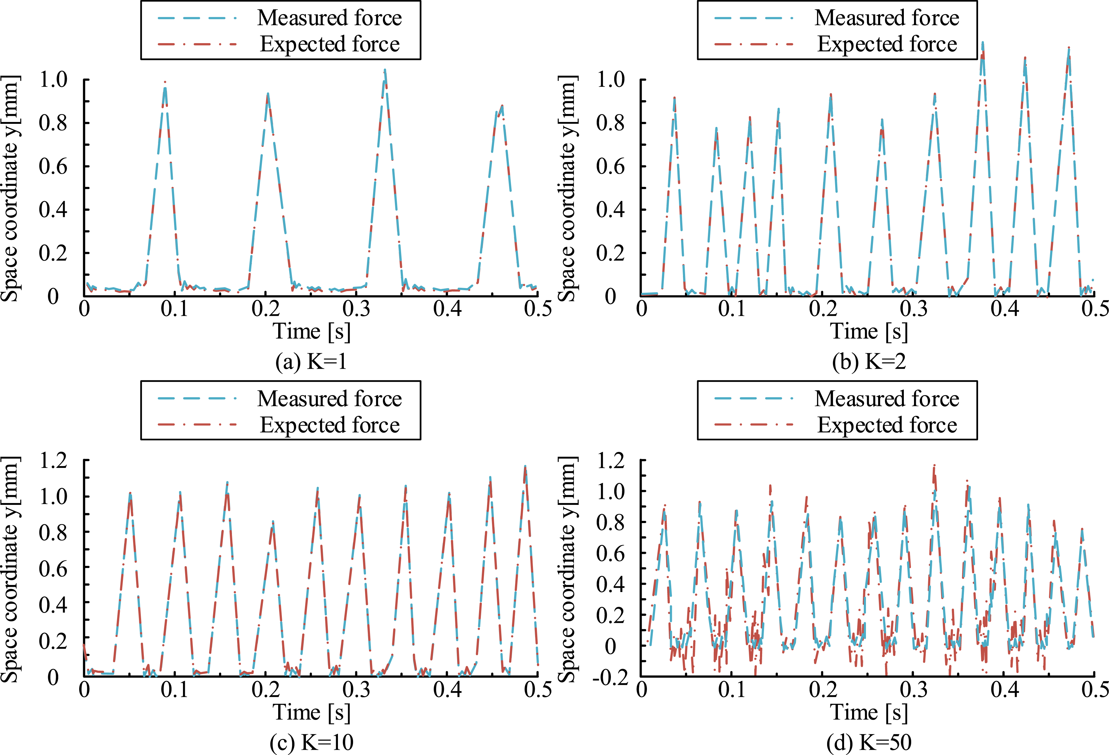
In Figure 10, the force tracking performance of the system varied with the variation of the stiffness parameter k. In Figure 10(a) and (b), when k was 1 and 2, the measured force and the desired force curves were basically coincident between 0 and 0.5 s, with a slight offset. When k = 1, the measured force was slightly lower than the desired force near 0.2 s. However, the overall trend was consistent, which indicated that the system was able to follow the change of external force better. From Figure 10(c) and (d), at k = 10 and 50, although the measured force was still close to the desired force in the initial stage, the measured force curve showed obvious up and down jitter with time, which deviated from the desired force. For example, at k = 50, the jitter was intensified after 0.4 s. This indicates that the system can follow the change of external force better. The stiffness coefficient should be no more than 10 under the premise of ensuring accurate force and position following and system stability. Excessive stiffness can cause the system to become too rigid, resulting in frequent small oscillations and instability when subjected to force. Figure 11 shows the force and position during finishing with different robotic arms. Experimental results of interior wall decoration design model. (a) Comparison of the end tracks of the two robot arms moving along the wall in a straight line (b) The change of force and position during the contact between the plaster actuator and the wall.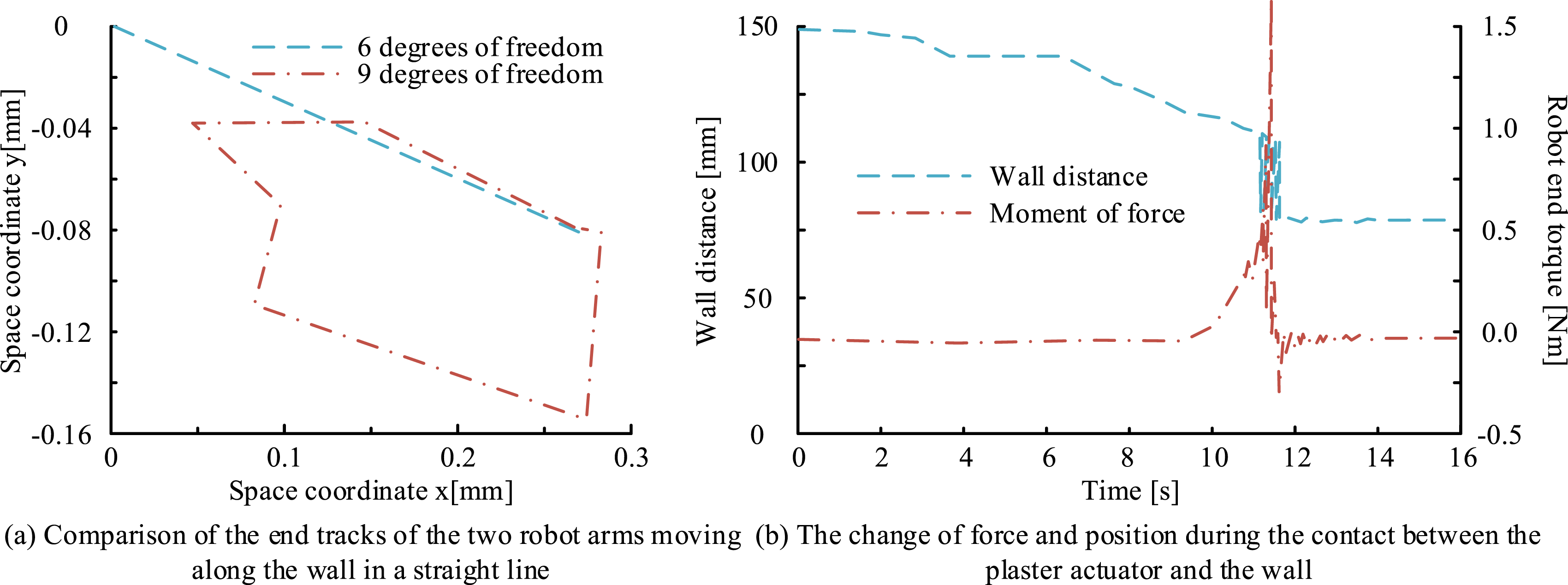
Quantitative analysis results of the comparison between six-degree-of-freedom and nine-degree-of-freedom robotic arms.
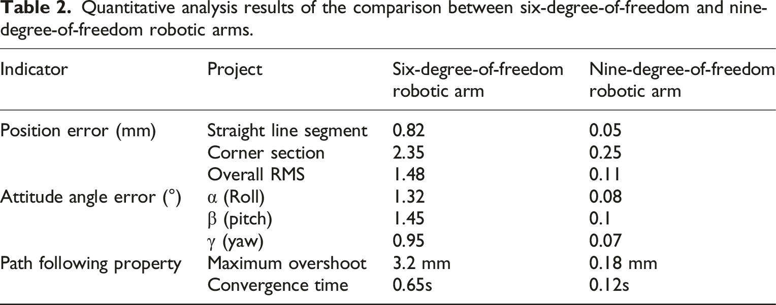
Table 2 compares the quantitative analysis results of the trajectory tracking performance of six-degree-of-freedom and nine-degree-of-freedom robotic arms. The displacement errors of the six-degree-of-freedom robotic arm in the straight line section and the corner section were 0.82 mm and 2.35 mm, respectively, while the nine-degree-of-freedom robotic arm was significantly superior, being 0.05 mm and 0.25 mm, respectively. From the perspective of overall root mean square error, the six-degree-of-freedom robotic arm was 1.48 mm, while that of the nine-degree-of-freedom robotic arm was only 0.11 mm, highlighting the significant advantage of the latter in terms of accuracy. In terms of attitude angle errors, the six-degree-of-freedom robotic arm had relatively high errors in pitch, roll, and yaw angles, which were 1.32°, 1.45° and 0.95°, respectively, while the errors of the nine-degree-of-freedom robotic arm were significantly reduced to 0.08°, 0.1° and 0.07°. In terms of path tracking characteristics, the maximum overwear and convergence time of the nine-degree-of-freedom robotic arm were significantly better than those of the six-degree-of-freedom robotic arm, which were 0.18 mm and 0.12s, respectively. These results indicate that the nine-degree-of-freedom robotic arm demonstrates significant advantages in both accuracy and response speed, making it suitable for application scenarios that require higher flexibility and precision.
Real-world deployment verification of decorative robots
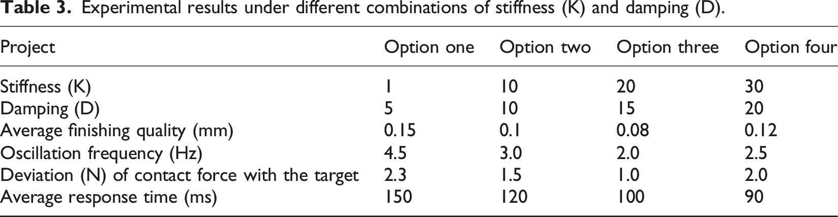
Experimental results under different combinations of stiffness (K) and damping (D).
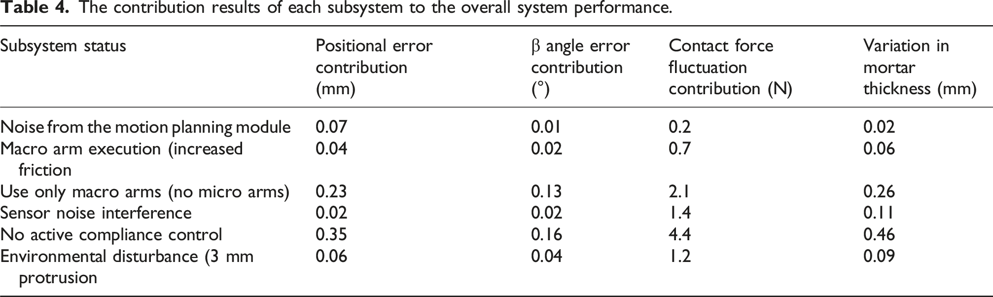
The contribution results of each subsystem to the overall system performance.
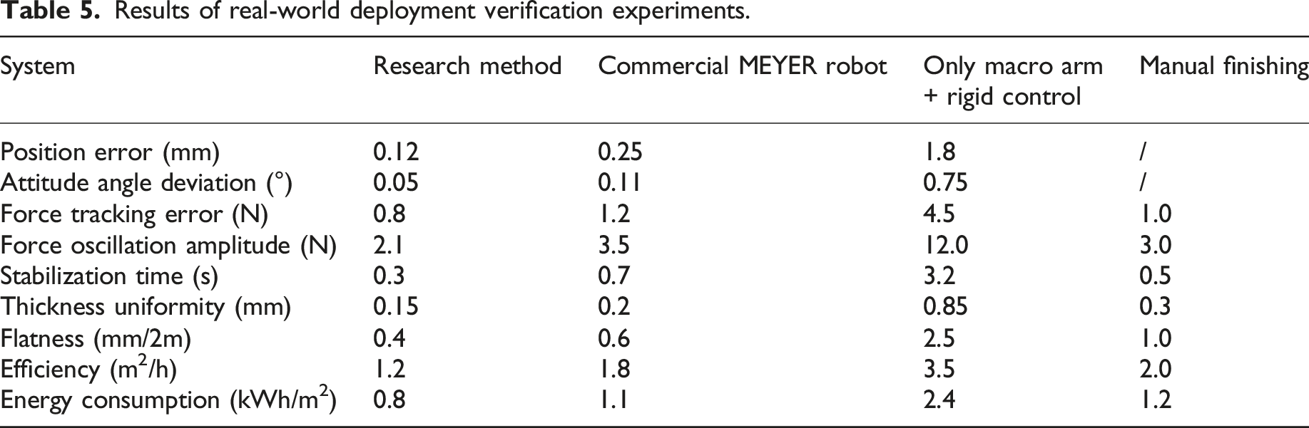
Results of real-world deployment verification experiments.
Comparison of construction efficiency under different temperature and humidity conditions.
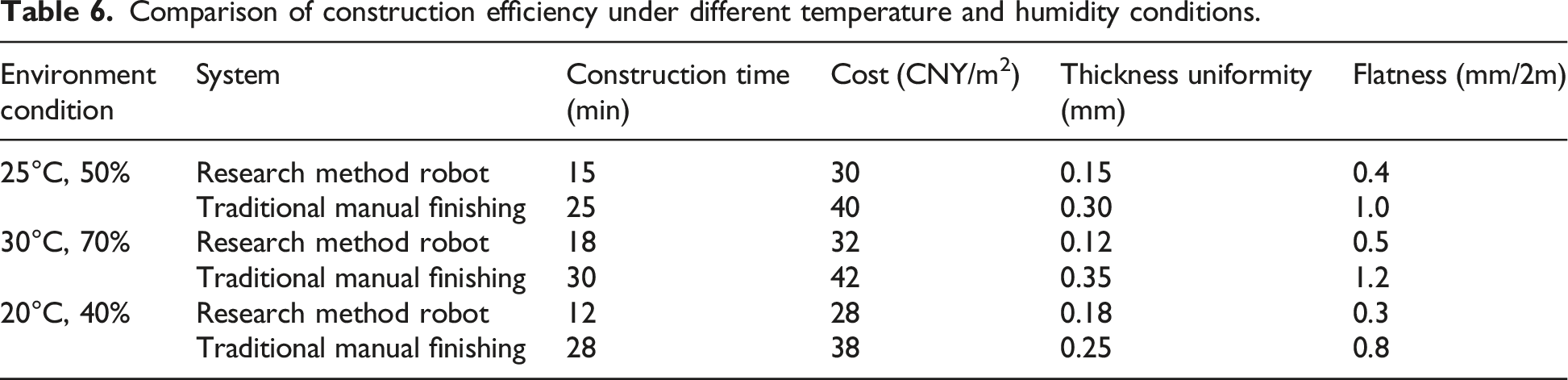
Table 6 shows the construction efficiency of the indoor wall decoration robot and the traditional manual finishing under different temperature and humidity conditions. Under standard environmental conditions of 25°C and 50% humidity, the robot took 15 min to complete the finishing work, with a cost of 30 CNY/m2. The thickness uniformity was 0.15 mm and the wall flatness was 0.4 mm per 2m. In contrast, traditional manual finishing took 25 min and costs 40 CNY/m2. The thickness uniformity and the flatness of the wall surface were 0.30 mm and 1.0 mm, respectively, demonstrating the obvious advantages of the robot on time and quality. In a high-temperature and high-humidity environment of 30°C and 70% humidity, although the robot construction time slightly increased to 18 min and the cost was 32 CNY/m2, compared with the 30 min and 42 CNY/m2 of manual finishing, it still demonstrated higher efficiency and cost-effectiveness. In addition, under this condition, the thickness uniformity and wall flatness of the robot were also more outstanding, being 0.12 mm and 0.5 mm, respectively. In a low-temperature and low-humidity environment of 20°C and 40% humidity, the robot performed best, taking only 12 min and at a cost of 28 CNY/m2. The thickness uniformity and wall flatness were 0.18 mm and 0.3 mm, respectively, which had significant advantages over manual finishing at 28 min, 38 CNY/m2, 0.25 mm, and 0.8 mm. In the experimental results, the actual driving delay and hysteresis effect had a significant impact on the performance of the interior wall decoration robot. Although the control model assumes that the actuator can immediately respond to control instructions, in practical applications, the system often cannot achieve ideal instant feedback due to friction in the mechanical structure, response time of the actuator, and elastic deformation between connecting components. This delay may lead to fluctuations in contact force and unevenness in finishing thickness, thereby affecting the overall project quality. The robot in the research successfully reduces the negative impact in this regard through advanced motion planning and active compliance control strategies. For instance, in a high-temperature and high-humidity environment, although there is a certain lag effect during the experiment, the robot can still maintain excellent performance. The construction time and contact force errors are significantly lower than those of traditional manual finishing and robots that only use macro robotic arms. This indicates that with the help of multi-degree-of-freedom mechanical design and adaptive control, robots under the research method can timely correct their trajectories and adjust the applied forces with rich dynamic feedback.
Although the research focuses on the design and control of automated wall decoration robots, in the actual construction process, the ideal state of completely replacing human labor is often difficult to achieve. Therefore, the feasibility and effectiveness of human-machine collaboration are of great significance. Human–machine collaboration can adapt the construction process to various irregular and complex environments by combining the high-speed and precise operation of robots with the flexible decision-making of humans, thereby enhancing the overall construction efficiency. For instance, when it comes to complex wall designs and unexpected situations, humans can quickly adjust their strategies, while robots can maintain high efficiency in standardized tasks. Effective teamwork not only improves construction quality, but also reduces safety risks and enhances the adaptability of the working environment, thereby promoting the comprehensive intelligentization process of the industry.
Conclusion
To improve the quality of wall decoration, reduce labor intensity, and enhance the precision and efficiency of interior wall finishing, an innovative decorating robot finishing method was proposed. An intelligent decoration system integrating a macro/micro composite robotic arm and a force-controlled finishing terminal was designed, and a cooperative control architecture was established. The test results showed that the spatial error between the calculated value and the actual value of the end trajectory position of the robotic arm was lower than that of the detection threshold, and the attitude matching degree reached the standard of process requirements. The joint rotation angle of the mechanical body was limited to the preset safety interval, and the movement speed of the micro robotic arm was strictly in the preset safety range. In the force-position co-control of the finishing actuator, the optimal tracking stability was demonstrated when the system stiffness parameter was set to 10. With the help of a laser positioning system, the attitude parallelism error between the end of the robotic arm and the work plane is dynamically eliminated, confirming the effectiveness of redundant motion control logic. The study verified the effectiveness of redundant motion control algorithms for macro/micro robotic arms and active compliant controllers based on impedance control, further improving the parallel posture maintenance of the robotic arm end towards the wall and the adaptability of the finishing actuator to the wall. Although research has achieved certain results, there is still room for improvement. Future research will further optimize the robot’s ability to perceive and adapt to complex wall environments, and enhance its operational performance under different materials and textures. Meanwhile, the integration of active compliance control and force feedback mechanism will be explored in depth to better meet the diversified needs of wall finishing.
Footnotes

Funding
The authors received no financial support for the research, authorship, and/or publication of this article.
Declaration of conflicting interests
The authors declared no potential conflicts of interest with respect to the research, authorship, and/or publication of this article.