
Abstract
The feathers of owls possess three adaptations that are held responsible for their quiet flight. These are a comb-like structure at the leading edge of the wing, fringes at the trailing edge, and a soft and porous upper surface of the wing. To investigate the effect of the first adaptation, the leading edge comb, on the aerodynamic performance and the noise generation during gliding flight, wind tunnel measurements were performed on prepared wings of a Barn owl (Tyto alba) with and without the comb. In agreement with existing studies it was found that the leading edge comb causes a small increase in lift. Additionally, at high angles of attack the results from the acoustic measurements indicate that the presence of the comb leads to a reduction in gliding flight noise. Although this reduction is relatively small, it further helps the owl to approach its prey during the final stages of the landing phase.
Introduction
In 1934, Graham 1 identified three adaptations of the feathers of owls that are held responsible for the quiet flight. These are (1) “a remarkably stiff, comb-like fringe on the front margin of every feather that functions as a leading edge”; (2) a fringe “along the trailing edge of the main wing and of each primary feather”; and (3) a fine, short down that covers “certain parts of the upper surface of the feathers.” The existence of these adaptations and their possible effect on the silent flight of the owl has been the subject of several studies in the past. The knowledge regarding the role of the leading edge comb for the noise generation and the aerodynamic performance of owls is based on only a few, sometimes quite old publications. In some cases, experimental results show a relatively large variance, making it hard to draw a final conclusion.
Mascha 2 examined feathers of different birds and assumes that the special features he found at the feathers of owls, among them an upward bending of the outer branches on the feathers building the wing leading edge, are responsible for their silent flight. Graham 1 suspects that the main function of the leading edge comb is to locally reduce the velocity of the incoming flow and, additionally, to deflect the flow in a way that it meets the real leading edge under a smaller angle. Hertel 3 states that the leading edge comb affects the boundary layer in a way that the incoming flow becomes turbulent when it passes the hooks. He further assumes that the comb somehow prevents stall and “other acoustically unfavorable processes.”
In the 1970s, a number of experimental investigations were performed on flying owls or prepared wings in order to further explore the role of the leading edge comb. For example, Kroeger et al.
4
and Gruschka et al.
5
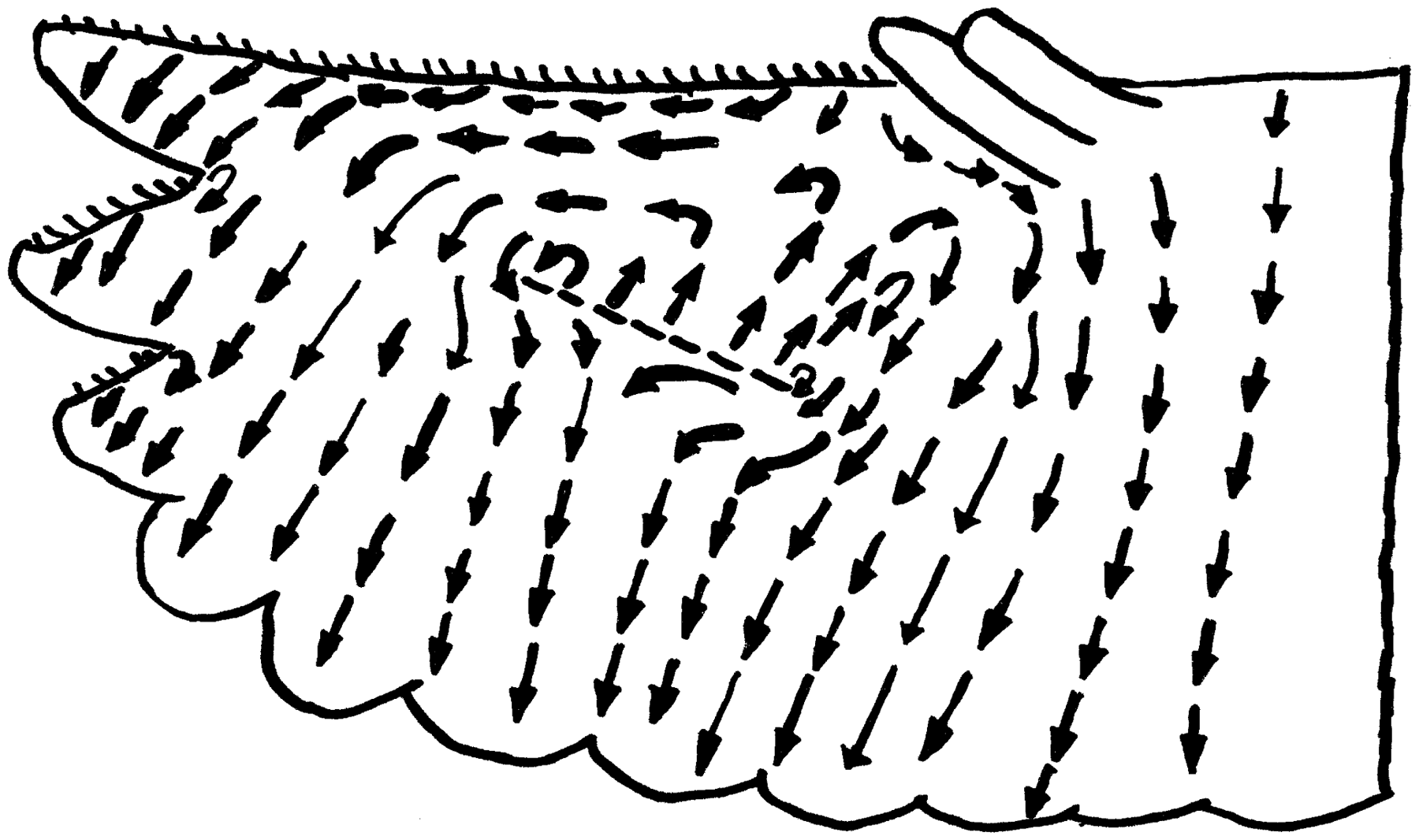
performed a detailed experimental study on a Florida barred owl (Strix varia alleni), with and without the leading edge comb. The owl flew along a certain path inside a reverberation chamber, where measurements were made using a single condenser microphone. Figure 1(a) gives the resulting sound pressure levels obtained from these measurements. The data show a relatively large variance of the results from the same owl with the leading edge comb intact, thus making it difficult to observe a distinguishable acoustic effect of the comb. To draw conclusions on gliding flight aerodynamics, the length of the flight path and the flight time were measured and a lift-to-drag ratio of 2.25 was calculated, thus characterizing the owl as a “low performance flyer.” Besides the flyover measurements, flow visualization tests were also performed in a wind tunnel on the “wing from a small owl,” which had a span width of 0.457 m and a wing area of 0.0465 m2. The experiments were done using cigar smoke and a tuft probe. At low angles of attack, no effect of the leading edge comb was found, whereas at high angles the comb “developed a vortex sheet which allowed the flow in the boundary layer to be initiated in the outboard direction.” Kroeger et al. provided a sketch of the flow field around the owl wing, which is reproduced in Figure 2. It is important to note that, although the flow field is quite complex and consists of areas of counterrotating flow, the flow remains laminar even at very large angles of attack above 30°. When the comb was removed, the areas of counterrotating flow were “replaced by a single large system with the flow being directed inboard at the leading edge.” Additionally, with the comb removed flow separation occurred (the flow reattached near the trailing edge) and “considerable turbulence” was observed.
Third octave band sound pressure levels obtained from past flyover measurements of owls with and without the leading edge comb, normalized to a distance of 1 m. (a) Results from flyover measurements of Kroeger et al.
4
on a Florida barred owl (the data with the leading edge comb intact were derived from four individual measurements of the same bird) and (b) results from flyover measurements of Neuhaus et al.
6
on a Tawny owl. Streamline pattern over the suction side of an owl wing as provided by Kroeger et al. (redrawn from Kroeger et al.
4
).
The data provided by Kroeger et al. were later revisited by Anderson 7 , who states that the removal of the leading edge comb in Kroegers experiments failed to show a change in flight performance due to the relatively high glide angle in the experiments. He examined the wings of a Great horned owl (Bubo virginianus) and concluded that the lift-to-drag ratio is much higher than the value given by Kroeger.
Another investigation of the effect of the leading edge comb was included in the study by Neuhaus et al. 6 They measured the gliding flight noise of a Tawny owl (Strix aluco) with and without the leading edge comb using a single microphone and a signal analyzer. Their results are shown in Figure 1(b). Again, the differences are relatively small, and the authors themselves state that they are below the accuracy of the measurement instrument. Additionally, smoke flow visualization experiments were performed on approximately 10 mm wide strips of prepared wings from a Tawny owl and a mallard (Anas platyrhynchos). The tests were conducted in a wind tunnel at a flow speed of 3 m/s and an angle of attack of 6°. It was found that the flow around the owl wing is essentially laminar, while large regions of turbulence developed at the pressure side and suction side of the mallard wing. Additionally, a small zone of turbulent circulation was observed near the comb, and it was concluded that it may serve to reattach the flow. When the leading edge comb was removed, the flow around the owl wing was similar to that around the mallard wing, although the regions of turbulence were smaller.
The silent flight of owls was also studied by Lilley, 8 who revisited the data provided by Kroeger et al. and concludes that the comb stabilizes the flow over the suction side of the wing and prevents laminar separation. Thus, the aerodynamic purpose of the comb is to allow the owl to fly stable at very low speed. Regarding its acoustic effect, Lilley concludes that, by keeping the flow attached, the boundary layer thickness is effectively reduced, leading to a reduced noise generation at the trailing edge.
An extensive work on the special features of the plumage of a Barn owl (Tyto alba) was done by Bachmann 9 and Bachmann and Wagner. 10 This includes three-dimensional scans of the leading edge comb and, as a consequence, a very detailed description of its geometry.
In a recent work by Weger and Wagner, 11 the comb-like structures of seven different owl species were examined using a camera, stereo microscopy, and a laser scanning microscope. It was found that comb-like structures of nocturnal owl species featured a larger inclination angle, a larger tip displacement angle, and a greater length compared to those of species that are more active during the day. Since nocturnal species are more dependent on their hearing when attempting to capture prey, it was concluded that the serrations have to be involved in reducing flight noise.
A recent review of the special feather adaptations of owls was given by Wagner et al., 12 including detailed information on the leading edge comb.
Another feature of bird wings that may affect the flight performance and the noise generation, especially in combination with the leading edge comb of the owl, is the so-called alula or bastard wing. A very detailed study of the aerodynamic effect of the alula was done by Nachtigall and Kempf, 13 who performed measurements on prepared wings of four birds (two sparrows, a blackbird, and a mallard) inside a wind tunnel. They found that the alula leads to an increase in lift at high angles of attack ranging from 30° to 60°, with an average increase of the lift coefficient of 11%. In a later publication, Nachtigall 14 summarizes these results and states that the function of the alula is to prevent stall in situations where the angle of attack is very high (e.g. during start, landing, and when turning). According to Anderson, 7 the alula consists of “three or four short feathers that act as a controllable aerodynamic thumb” (see e.g. Figure 2). In the work of Kroeger et al. 4 this system of feathers, which is located approximately at midspan, is compared to a slat. They state that the combination of the leading edge comb, the alula, and the slotted wing tip produces the special vortices that are responsible for the unique flow structures that are developed over the wings of an owl, including the outward facing flow. Anderson 7 states that during the flight tests conducted by Kroeger et al. the alula was “held slightly open and swept forward.” Additionally, he performed flow visualization experiments on airfoil models with and without the presence of a small winglet that acted as an alula. Anderson observed that the winglet delayed stall and developed a vortex field that helped to create the counterrotating flow pattern described by Kroeger. Bachmann 9 states that the alula is an “antistall device” which, when erected, gives the bird additional lift at critical angles of attack, for example during the landing phase of flight. More recently, Lee et al. 15 performed aerodynamic wind tunnel measurements on four prepared wings of an Eurasian magpie (Pica pica), with and without the alula. They found that, while the drag force was not substantially affected by the presence of the alula, it led to a noticeable increase of the lift force at high angles of attack and helped to delay stall. However, currently little is known about the effect of the alula with respect to the leading edge comb of an owl.
Concluding this review, it becomes obvious that the available acoustic data either show a relatively large variance or the differences between cases with and without the leading edge comb are simply below the accuracy of the measurement instruments. Hence, a noticeable acoustic effect of the leading edge comb has only been suspected but is hardly visible in the existing data. Based on the existing literature it seems likely that the comb-like structure at the leading edge of an owl wing, especially in combination with the alula as a vortex generator, merely serves aerodynamic purposes by keeping the flow laminar even at high angles of attack, thus delaying stall.
The present experimental work was motivated by a study of the silent owl flight using a set of prepared bird wings by Geyer et al. 16 In that work, detailed wind tunnel measurements were performed on wings from two owl species and from three not silently flying bird species. It was shown that the low noise generation of owls is indeed a consequence of their special wing and feather adaptations and not only of their lower speed of flight. However, a question that was not addressed in that investigation was how much each of the single adaptations individually contributes to the silent flight.
Therefore, in the present study the role of the first feather adaptation, the so-called leading edge comb, is investigated by performing wind tunnel measurements on prepared owl wings with and without the comb-like structure. The remainder of this paper is organized as follows: In the following section, the experimental setup is described in detail. This includes a six-component force sensor, microphone array technique, and approaches to investigate the flow field around the owl wing and the deformation of the wing under load. Additionally, preliminary aerodynamic tests using an artificial alula are described. Then, results are presented and discussed. In the last section, the findings of the present study are summarized.
Experimental setup
All measurements took place in the aeroacoustic wind tunnel at the Brandenburg University of Technology Cottbus—Senftenberg using microphone array technique and a six-component force sensor.
Prepared wings
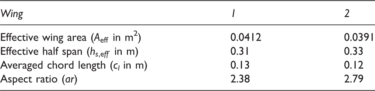
In total, measurements were performed on two prepared wings of the Barn owl, which were chosen from a larger set of specimen used in the study of Geyer et al.
16
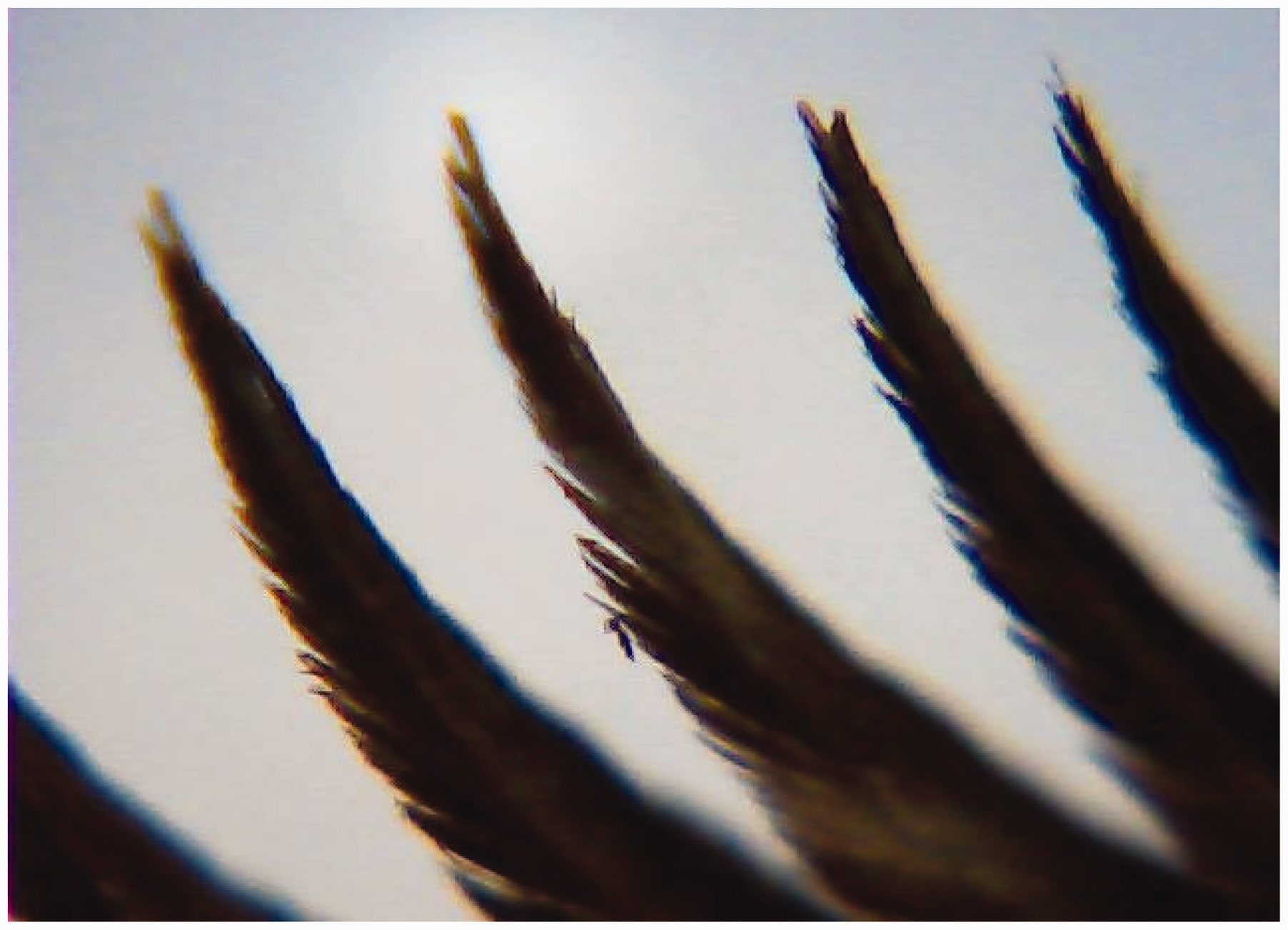
according to their suitability for the purpose of this study. Figure 3 shows a photograph of one of the wings as well as a detailed photograph of its leading edge comb. The hooks of the comb, which are quite solid barbs with branched tips, were further examined using a Bresser optical microscope with a magnification of 4×, shown in Figure 4.
Photograph of a prepared wing used for the experiments (wing 2 from Table 1). (a) Complete wing and (b) leading edge hooks. Microscope image (magnification 4×) of the hooks from wing 1.
Properties of the prepared wings used for the present study.
In the course of the study, experiments were first conducted using both wings with their leading edge combs intact. The combs were then removed using a scalpel and the experiments were repeated, thus allowing to draw conclusions on the effect of the comb.
Wind tunnel
The small aeroacoustic wind tunnel at the Brandenburg University of Technology is an open jet wind tunnel (see Sarradj et al.
17
). For the experiments on prepared wings, a circular nozzle with an exit diameter of 0.35 m was used. With this nozzle, the maximum flow speed is about 40 m/s, while the turbulence intensity in the core jet (measured at 10 and 15 m/s) remains below 0.2% (as described in Geyer et al.
16
). Figure 5(a) shows a photograph of the measurement setup inside the aeroacoustic wind tunnel facility.
Measurement setup inside the aeroacoustic wind tunnel. (a) Photograph and (b) schematic (top view).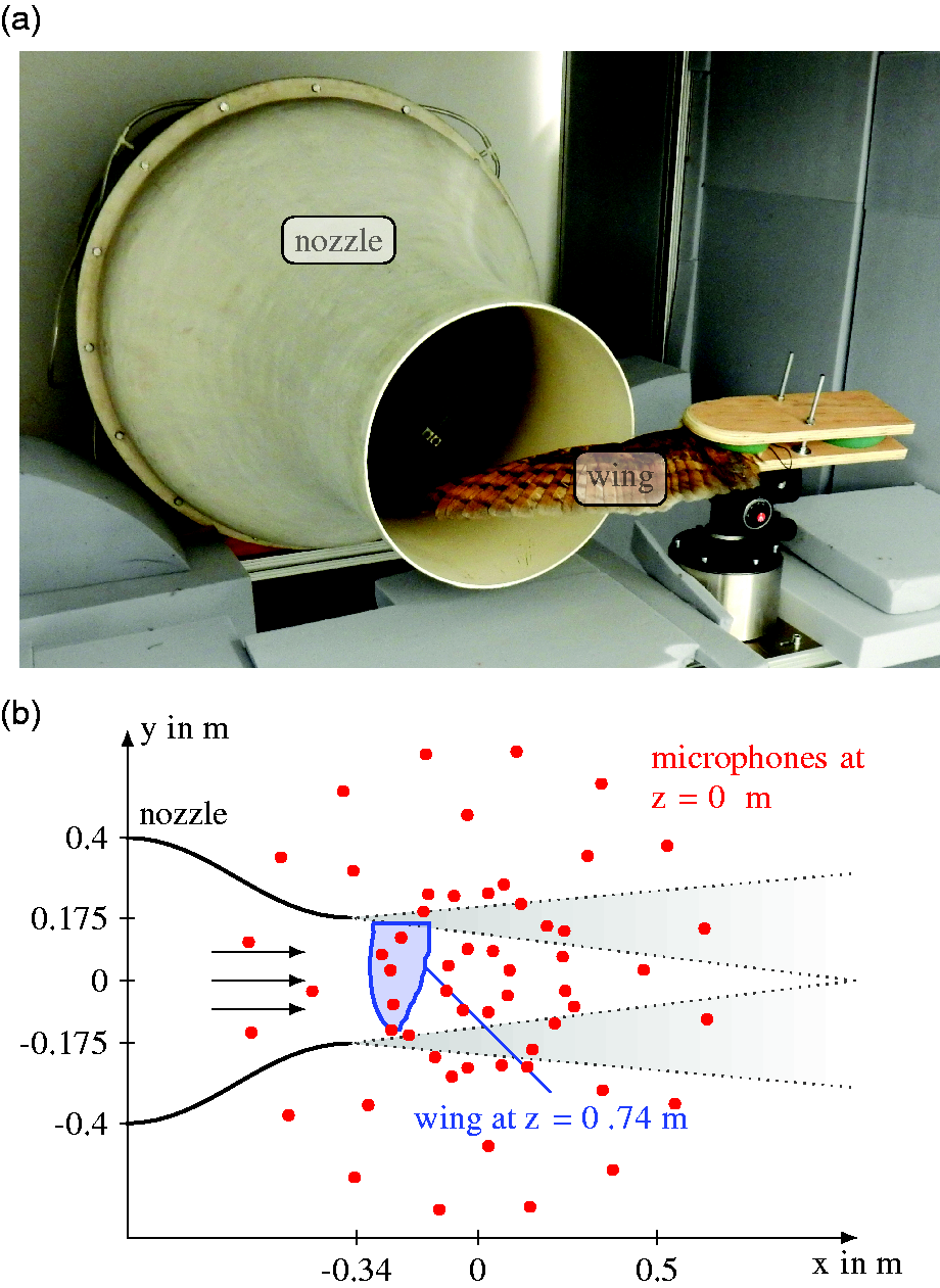
For the measurements, the wings were positioned in front of the nozzle (see Figure 5(b)) inside the test section. To this end, they were attached to a three-dimensionally adjustable pan/tilt head, which allows for the adjustment of angle of attack, sweeping angle, and flapping angle. As discussed by Geyer et al., 16 the geometric angle of attack was measured approximately at the midspan position using an electronic balance held under the wing. The sweeping and flapping angles were kept constant in a way that at zero angle of attack the wing area is approximately level and parallel to the x–y plane (see Figure 5). Surrounding the test section is an anechoic cabin with dimensions of 2.0 m (length) × 1.5 m (height) × 1.55 m (width). It has absorbing side walls, absorbers placed on the floor, and a planar microphone array for a ceiling. Thus, the measurement environment inside the cabin can be described as anechoic for frequencies roughly above 125 Hz.
It is known that owls fly quite slowly, according to Mebs and Scherzinger 18 their flight speed is only about 2.5–7 m/s, while according to Neuhaus et al. 6 it takes values up to 10 m/s. In order to investigate the behavior of the leading edge comb also at higher velocities, flow speeds between approximately 5 and 20 m/s were adjusted in the present experiments.
It is a known effect that the presence of a wing or an airfoil inside an open jet leads to a deflection of the jet and a curvature of the shear layer. As a result, the geometric angle of attack that is adjusted in such a setup is greater than the so-called effective angle of attack that would be obtained in free flow conditions. Unfortunately, common correction methods like the one proposed by Brooks et al. 19 are not practicable for the present case of prepared bird wings, which are highly three-dimensional and cambered. Therefore, the angles of attack of the present study are given to describe different configurations, but they cannot be compared directly to the angle of attack of a freely flying owl.
Aerodynamic force measurements
Aerodynamic measurements were performed on one of the wings using the six-axis sensor K6D154 made by ME Meßsysteme. The sensor measures forces and moments in all three spatial directions. It was positioned inside the test section in a way that the drag force acting on the wing corresponds to the force measured in x-direction, which has a nominal load of 30 N and a measurement uncertainty of ±0.05 N, while the lift force corresponds to the force measured in z-direction, which has a nominal load of 100 N and a measurement uncertainty of ±0.15 N. The data were recorded with a sampling frequency of 1 kHz and a measurement duration of 15 s using the amplifier GSV-1A16USB manufactured by the same company. The six-axis sensor provides six voltage signals, which were converted into three forces and three moments by multiplication with the sensor-specific calibration matrix.
When analyzing the aerodynamic data it has to be kept in mind that the angle of attack is adjusted manually by use of an electronic balance which is held under the wing at midspan. Therefore, a certain error of the measured forces due to small deviations of the angle cannot be completely avoided. When adjusted carefully, prior reproducibility measurements showed that the error in lift is below 0.1 N and that in drag below 0.02 N. One exception is the angle of attack of 12°, where at a flow speed around 12 m/s larger deviations in lift of up to 0.2 N occurred. It appears that the wing shape is very sensitive to even slight changes in angle of attack at this point.
In order to obtain at least a basic understanding of the function of the alula, especially in combination with the leading edge comb, a set of preliminary measurements was performed at 20° angle of attack and a constant flow speed of 10 m/s using an artificial alula. This artificial alula was simply cut from cardboard and positioned in the vicinity of the second wing from Table 1. Thereby, the approximate position and dimensions of this device were selected based on photographs of gliding owls and on the available literature (e.g. Kroeger et al.
4
and Anderson
7
). A schematic of the resulting setup is shown in Figure 6. Aerodynamic measurements were then conducted with and without the leading edge comb as well as with and without the artificial alula.
Schematic of measurement setup for tests with artificial alula (thumb wing) attached to wing 2 from Table 1.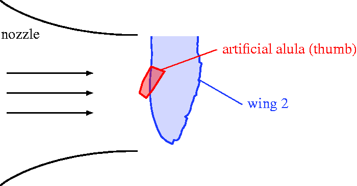
It has to be noted that due to the three-dimensional core jet and the expanding shear layers of the open jet, the aerodynamic forces obtained using the present setup are not directly comparable to values measured in a closed test section.
Flight noise measurements and data processing
The noise generated by the prepared wings was measured using a planar 56-channel microphone array, which was positioned outside the flow at a distance of approximately 0.74 m above the wings. In total, 40 s of data were recorded with a sampling frequency of 51.2 kHz. In postprocessing, which was performed using the Acoular software package (see Sarradj and Herold 20 ), the time–data were converted to the frequency domain using a fast Fourier transformation with a Hanning window on 50% overlapping blocks of 4,096 samples. The resulting spectra were averaged to yield the final cross-spectral matrix.
As in the study of Geyer et al., 16 the CLEAN-SC beamforming algorithm developed by Sijtsma 21 was applied to the measured data, using a steering vector corresponding to Formulation IV in the work of Sarradj. 22 Thereby, noise sources are assumed to be located within a fully three-dimensional source region. In each spatial direction, the resolution of the focus grid was 0.01 m, leading to a total of 102,541 grid points. The result from this procedure is a three-dimensional mapping of noise sources, a so-called sound map. In order to obtain spectra of the noise generated by the wings, the noise originating from sources located at the wing was integrated. This integration was done using a three-dimensional integration volume that contained only the part of the wing located inside the wind tunnel core jet, but no background noise sources. Finally, the integrated sound pressures were converted to third octave band sound pressure levels.
Due to the fact that the flow speeds are quite low in the present experiments, no correction for the refraction of sound at the shear layer of the open jet was applied in the data processing for the sound pressure level spectra. However, in order to allow for basic conclusions on the noise source locations, two-dimensional sound maps were analyzed. For these cases, the correction method proposed by Sarradj 23 was applied, which uses ray tracing to account for refraction effects at the shear layer.
Flow visualization
In order to obtain a qualitative understanding of the flow field around the prepared owl wings, flow visualization experiments were conducted using a tuft probe. It consisted of a thin tuft attached to a holder, which was brought close to the wing surface at different positions on the wing. This provides a very simple method to observe the local direction of the flow, since the tuft will align with the mean flow direction. Additionally, basic conclusions can be drawn on the turbulence of the flow, as the tuft will perform unsteady motions when subject to turbulence and will be immobile when no turbulence is present (see Merzkirch 24 ). The orientation and movement of the tuft was filmed using a handheld camera.
Estimation of wing deformation
Especially at higher flow speeds and angles of attack, the prepared wings will be deformed due to the dynamic pressure of the flow. This deformation has a strong effect on the aerodynamic performance. In an early study by Nachtigall and Wieser 25 on the aerodynamic performance of a pigeon (Columba livia) wing in a wind tunnel, it was found that the camber of the wing reduces with increasing flow speed and increasing angle of attack. Kroeger et al. 4 noticed deformations of the wing and found that they are strongly dependent on angle of attack. In the experimental work of Withers, 26 the examined wing specimen did not bend, leading to constant lift and drag coefficients. This, however, was attributed to the relatively small range of flow velocities. It was discussed that the coefficients “would vary markedly over wider ranges” of speeds. Knappe and Wagner 27 calculated the effect of elasticity on the aerodynamic performance, based on airfoil shapes derived by Nachtigall and Wieser 25 from pigeon wings. According to their study, the deformation of the wing leads to the fact that the lift coefficient does not increase linearly with angle of attack. Instead, after the lift coefficient first increases for the elastic wing as well (although with a smaller slope), it then decreases again with further increasing angle. Significant deformations also occurred in the study of March et al., 28 who measured the lift and drag coefficients of a Great horned owl wing. They observed “tremendous flutter of the wing” at high angles of attack. In cases, where the aerodynamic load led to a bending of the feathers, but not yet to a full rotation of the wing, a reduction of the lift curve slope was found. However, it was also stated that, since a bird wing will deform and twist into the flow, no flow detachment will occur and hence the wing will not stall. Thus, the aeroelasticity of the wings makes them adaptable to various flight regimes.
In order to obtain a rather qualitative measure of the deformation of the prepared wings in the present study, a camera was positioned downstream of wing 1 that captured the wing shape under load. The camera was a CCD monochrome camera that recorded 60 frames per second. Additionally, a common ruler was used to get an estimate of the displacement of the wing tip as a quantitative measure of the wing deformation.
Results and discussion
Aerodynamic force measurements
The resulting lift and drag forces from the aerodynamic measurements are shown in Figure 7(a) and (b), respectively. Basically, at each angle of attack the lift force first increases with increasing flow speed up to approximately 12 m/s. With further increasing flow speed, the lift force starts to decrease. Hence, the owl wings do not show the typical dependence of the lift force on U2 that would be expected for a technical airfoil. This is due to the aforementioned deformation of the wing caused by the increasing aerodynamic load, effectively leading to a reduction in camber and thus a reduction in lift. This result is in agreement with the findings from previous studies discussed above (like Nachtigall and Wieser,
25
Knappe and Wagner,
27
and March et al.
28
). The drag force (Figure 7(b)) continuously increases with increasing flow speed. Here, the deformation of the wing leads to the fact that, starting at flow speeds above 15 m/s, the drag force reaches the same high value for all angles of attack.
Lift and drag forces measured for wing 2 from Table 1, solid lines: comb intact, dashed lines: comb removed (from dark blue to brown color: α = 0°, 4°, 8°, 12°, 16°, 20°, 24°). (a) Lift force and (b) drag force.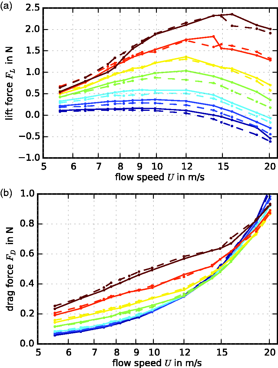
Regarding the effect of the leading edge comb it is visible that without the comb the lift force is lower than with the comb intact. The only exception is at flow speeds below 10 m/s for α = 20° and α = 24°. Although the increase in lift due to the existence of the comb is not very large, the effect is significant since it can be observed at nearly all angles and flow speeds. The influence of the comb on the drag force is very small only and more or less within the accuracy of the aerodynamic measurements as described before.
The preliminary tests with the artificial alula (at 20° angle of attack and a flow speed of 10 m/s) revealed that with the leading edge comb intact, the presence of the alula led to an increase in lift of about 2.4%, while without the hooks the increase in lift was 1.2%. Basically, these results confirm the assumed role of the alula as a device to increase lift. They also indicate that this effect is enhanced by the comb, although the rather simple experimental approach of the present study will more or less yield only basic estimates, of course. Since according to Nachtigall and Kempf 13 the alula is effective at rather large angles of attack from 30° to 60°, it is possible that measurements at even higher geometric angles of attack may have given a clearer trend. Hence, to fully investigate the function of the alula, future experiments should be conducted at higher angles of attack, using a larger set of prepared wings with the alula erected and those with the alula held flush against the wing.
Flight noise measurements
As noticed in the acoustic results obtained by Kroeger et al. (see Figure 1(a)), the results obtained in the present measurements do not show a very clear trend regarding an effect of the leading edge comb on the gliding flight noise. Basically, an acoustic effect was only seen for one of the two wings (wing 1 from Table 1). The data obtained for the second wing did not allow to draw a clear conclusion on the effect of the comb on the gliding flight noise, which of course limits the significance of the acoustic results from the present study. The reason for the differences between the results for the two wings is not clear. To fully explore this effect, additional measurements on a larger number of wing specimens would have to be performed.
However, in order to allow at least a basic understanding of the possible effect of the comb on the noise generation, the following discussion will only refer to the acoustic results obtained for the first wing from Table 1.
Basically, the acoustic data obtained for wing 1 show no difference at low angles of attack, as shown in Figure 8(a) for α = 0. At higher angles of attack, a distinct trend can be derived that the comb leads to a distinct noise reduction (as shown in Figure 8(b) for an angle of 24°). Thus, the sound pressure level spectra shown in Figure 8 indicate that, on average, the leading edge comb does lead to a reduction in gliding flight noise at higher angles of attack, although this has to be described as a rather small-scale effect. Nevertheless, it has to be kept in mind that the maximum geometric angle of attack that can be adjusted with the present experimental setup corresponds to a much lower value under free flight conditions. Hence, it is possible that the effect shown here is more pronounced at higher angles of attack.
Measured sound pressure levels (solid lines: comb intact, dashed lines: comb removed) of wing 1 from Table 1. (a) Sound pressure level spectrum at α = 0° and (b) Sound pressure level spectrum at α = 24°.
In order to investigate the influence of the leading edge comb on the location of the noise sources on the wing surface, two-dimensional sound maps will be analyzed. These maps were generated for the same wing for which spectral results are shown in Figure 8, using a common delay-and-sum beamforming algorithm (Mueller). 29
Sound maps obtained at a flow speed of 9.9 m/s and a geometric angle of attack of 0° for third octave bands with center frequencies from 1 to 2.5 kHz are displayed in Figure 9. It can be concluded that, at this flow speed and angle of attack, the leading edge comb has no influence on the noise source locations. With and without the comb, the sources are more or less located within the center area of the wing, relatively close to the part where the wing is attached to the body of the bird (the forearm). In any case, the source positions are not at the trailing edge, which may be explained by the hypothesis that the other feather adaptations of the owl, especially the trailing edge fringes, are effectively reducing the trailing edge noise. This is in agreement with the results from the previous wind tunnel study by Geyer et al.
16
and with the findings from bird flyover measurements presented by Sarradj et al.
30
The sound maps presented in the latter study of a Common kestrel (Falco tinnunculus) showed the trailing edges and tips of the wings as sound sources at certain frequency bands, whereas no such distinct source positions were visible in the sound maps of a Barn owl. Sound maps obtained for a living pigeon flying in a wind tunnel, presented by Wei et al.,
31
also showed distinct sources at the wing tips, which are not visible for the owl wing in Figure 9.
Third octave band beamforming sound maps obtained for wing 1 from Table 1 at a flow speed of U = 9.9 m/s and a geometric angle of attack of 0°, left column: comb intact, right column: comb removed (note the small dynamic range of only 2 dB).
Sound maps obtained at approximately the same flow speed, but a higher geometric angle of attack of 24° are shown in Figure 10. Here, a clear effect of the leading edge comb can be seen: At medium to high frequencies (beginning at third octave bands with center frequencies of 1.25 up to 2.5 kHz), the main noise source is shifted toward the tip of the wing in the case when the leading edge comb is removed, while the sources remain at positions similar to those obtained at zero angle of attack in the case when the comb is intact. In addition, the noise source is notably stronger without the comb. This indicates that the leading edge comb prevents the development of a strong noise source at the wing tip (as would be visible for not silently flying birds and technical airfoils) at high angles of attack.
Third octave band beamforming sound maps obtained for wing 1 from Table 1 at a flow speed of U = 10.0 m/s and a geometric angle of attack of 24°, left column: comb intact, right column: comb removed (note the small dynamic range of only 2 dB).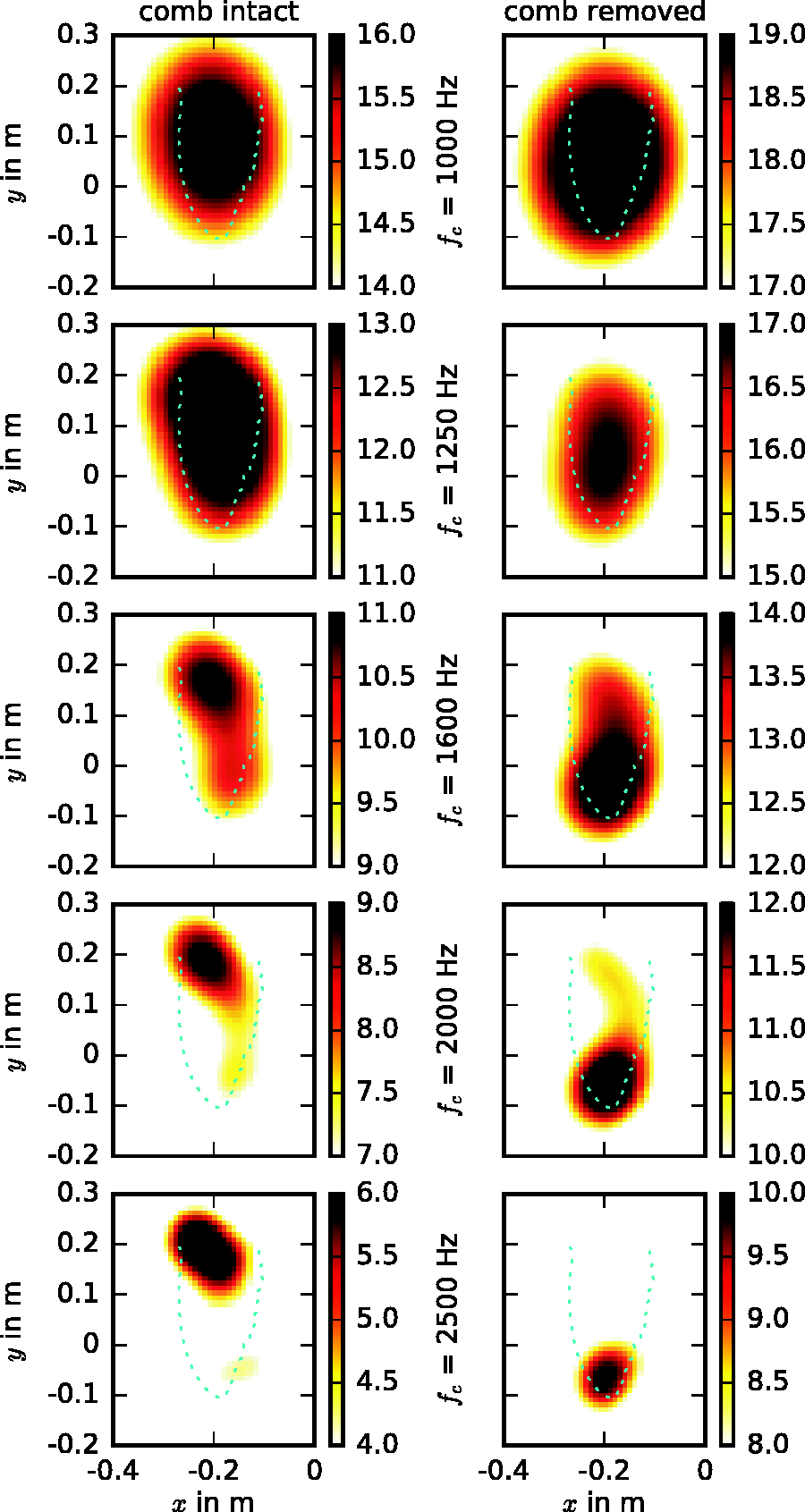
Flow visualization
Qualitative results of the flow visualization measurements on the first wing from Table 1 are shown in Figure 11 for three different flow speeds at a geometric angle of attack of 24°. The flow, which is directed toward the wing tip, was already observed at an angle of 20°, whereas at considerably lower angles this outward facing flow did not occur. Especially at 7 m/s (Figure 11(a)), the streamline pattern basically resembles the flow field observed by Kroeger et al.
4
as shown in Figure 2. At the highest flow speed of 15 m/s, certain features of the complex flow field, such as the outward facing flow and parts of the backward facing flow disappeared and a more regular flow over the wing developed. Somewhat different from the results from Kroeger, however, is the fact that with the comb removed almost the same flow field was observed, only with a stronger turbulence. This was visible through strong vibrations of the tuft. Additionally, the region of the outward facing flow was smaller when the comb was removed.
Results from flow visualization experiments on wing 1 at α = 24° (arrows represent streamlines of the flow over the wing surface, hatched areas represent regions with high turbulence and indistinct flow direction). (a) Flow speed U = 7 m/s, (b) flow speed U = 10 m/s, and (c) flow speed U = 15 m/s.
When comparing the flow visualization results at a flow speed of 10 m/s (Figure 11(b)) with the sound maps shown in the left column of Figure 10, it can be concluded that most of the noise originates from an area where the surface flow is directed downstream (near the root of the wing). Additionally, this also includes a small area of reversed flow.
Estimation of wing deformation
As a qualitative means to estimate the deformation of the wings due to the dynamic pressure of the flow, Figure 12 shows images recorded with the downstream camera for the first wing from Table 1. For three different angles of attack, the images contain both the wing at zero load (at U = 0) as well as under load (at U = 10 m/s). A noticeable deformation of the wing is visible, although conclusions regarding a potential effect of the leading edge comb on the deformation are not possible.
Qualitative results from deformation measurements at wing 1 for different angles of attack, U = 10 m/s, figures are a superposition of photographs with flow (upper wing position) and without flow (lower wing position). (a) comb intact, α = 0°, (b) comb removed, α = 0°, (c) comb intact, α = 12°, (d) comb removed, α = 12°, (e) comb intact, α = 24°, and (f) comb removed, α = 24°.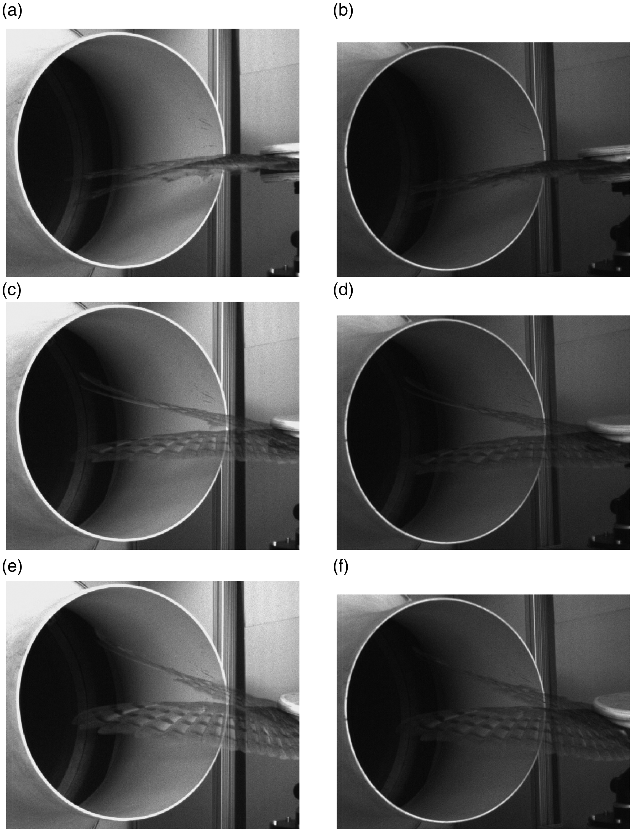
Figure 13 then shows the displacement of the wing tip as a function of flow speed. In total, measurements were performed at 7, 10, and 18 m/s. It is visible that at zero angle of attack the wing is bent down toward the pressure side. At positive angles (12° and 24°), the dynamic pressure leads to an upward bending of the wing toward the suction side. Additionally, it was observed that at higher angles of attack the wings were subject to oscillating motions.
Displacement of the wing tip (solid lines: leading edge comb intact, dashed lines: leading edge comb removed).
Although the accuracy of these measurements is restricted, the results indicate that at higher angles of attack the displacement of the wing tip is slightly higher without the leading edge comb. In combination with the findings from the flow visualization tests, this can be interpreted in a way that the leading edge comb helps to minimize the deformation of the wing and thus to keep the wing shape stable at high angles of attack.
Conclusion
This paper describes a set of experiments that were conducted on two prepared Barn owl wings in order to examine the function of the comb at the leading edge of owl wings. This included measurements of the aerodynamic forces, acoustic measurements using microphone array technology, and basic measurements of the wing deformation.
In general, the present investigation yields three main results: First, the comb at the leading edge leads to a small increase in lift, which basically confirms the findings from various studies performed in the past. Additionally, preliminary measurements using an artificial alula revealed that this device also helps to increase lift, which is again in agreement with past studies. Second, the present results suggest that the comb does indeed lead to a small reduction in gliding flight noise at high angles of attack. This noise reduction seems to be caused by the fact that the leading edge comb apparently prevents the development of a strong noise source at the wing tip, which only occurred in the case when the comb was removed. Usually, the owl increases the angle of attack in such a drastic way only near the end of the gliding flight phase, for example right before attacking its prey. Hence, a noise reduction, although relatively small, at this phase of the gliding flight further enables the nearly silent approach of the owl. Third, the measurements showed that the deformation of the wing is slightly smaller when the leading edge comb is intact. This indicates that the presence of the leading edge comb enables a more steady flight. Since a freely flying owl will have to actively counterbalance strong oscillations and deformations of its wings, this also means that the presence of the comb saves energy.
In addition to the acoustic and aerodynamic measurements, flow visualization experiments were performed using a tuft probe. The resulting sketch of the flow field over the wing at an angle of attack of 24° and a low flow speed (about 7 m/s) resembles the flow field observed in the fundamental study of Kroeger et al. 4
Footnotes
Acknowledgements
The authors thank Martin Päckert and Jens Ziegler of the Senckenberg Naturhistorische Sammlungen Dresden for the preparation of the wings and the helpful discussions.
Declaration of conflicting interests
The author(s) declared no potential conflicts of interest with respect to the research, authorship, and/or publication of this article.
Funding
The author(s) disclosed receipt of the following financial support for the research, authorship, and/or publication of this article: The wings used for this research were obtained during a study funded by the German Research Foundation in the priority program 1207, Nature Inspired Fluid Mechanics , under the grant number SA 1502/1-3.