



Abstract
Microphone arrays can be used to detect sound sources on rotating machinery. For this study, experiments with three different axial fans, featuring backward-skewed, unskewed, and forward-skewed blades, were conducted in a standardized fan test chamber. The measured data are processed using the virtual rotating array method. Subsequent application of beamforming and deconvolution in the frequency domain allows the localization and quantification of separate sources, as appear at different regions on the blades. Evaluating broadband spectra of the leading and trailing edges of the blades, phenomena governing the acoustic characteristics of the fans at different operating points are identified. This enables a detailed discussion of the influence of the blade design on the radiated noise.
Introduction
The aeroacoustic design of fans is an ongoing challenge. In general, the fan geometry is dictated by the intended aerodynamic performance and the geometric boundaries. However, the design choices made also have an influence on the acoustic characteristics of the fan.
Mechanisms influencing the noise generation of axial fans are well described in the literature. Sharland 1 identified several aerodynamic phenomena, such as vortex shedding and interaction with incident turbulent flow, causing the generation of broad-band noise. Several studies investigated noise generation due to vortices at the blade tip region.2–4 Considerable effort has been put into developing models to predict acoustic performance from the measurement of flow characteristics.5–9
Aside from affecting the characteristics of the resulting flow field, the skew of the fan blades has a noise reducing influence. In their survey of existing models addressing this, Carolus and Beiler 10 showed that the attribution of spectral characteristics to certain noise generating mechanisms, however, is still a matter of dispute. This is, in part, due to the fact that the experimental tools used for these investigations are limited to methods for characterizing the flow properties, while the acoustic properties are only evaluated through spectra for the respective fan as a whole. This makes it difficult to find effective measures to lower the overall noise emission or even address desired spectral characteristics of the fan through blade design.
Microphone array methods provide the possibility of localizing and quantifying multiple simultaneously emitting noise sources, 11 which makes them applicable as an acoustic design tool. Algorithms for processing array data are available in time domain and frequency domain. Delay-and-sum beamforming in the time domain can be applied for moving sources by continuously changing the focus distance.12,13 However, the spatial resolution achievable with classic delay-and-sum beamforming is limited. Advanced frequency domain methods, on the other hand, allow a higher resolution, but can only be applied on stationary sources. In the case of rotating sources and with appropriate measuring setup, however, it is possible to transform the data such that these sources appear stationary, which allows subsequent processing in frequency domain.14,15
In what follows, the aeroacoustic properties of three fans featuring backward-skewed, unskewed, and forward-skewed blades, respectively, are investigated experimentally. Measurements include different operating points, at which the aerodynamic and acoustic performance of the fans is evaluated. Major noise sources occurring on the fans are identified through the application of suitable microphone array data processing. Acoustic differences of the fan designs are discussed by means of leading and trailing edge (LE and TE, respectively) spectra. It will be shown that the noise generating mechanisms highly depend on the blade skew of the fan and its operating point.
Measurements and data processing
Experimental setup
Three generic fans featuring backward-skewed fan blades (fan B), unskewed fan blades (fan U), and forward-skewed fan blades (fan F) were investigated, see Figure 1. The fans were designed with a two-dimensional element blade method,16–19 as outlined in Zenger et al.
20
To obtain comparable results, the fans were designed to have a similar operating point. Common fan design parameters are shown in Table 1.
From left to right: backward-skewed fan, unskewed fan, and forward-skewed fan. Common fan design parameters.

In Table 1, the total-to-static pressure coefficient 

In equations (1) and (2), 
The fans differ in the fan blade skew and in the fan blade loading distribution
For fan U, no fan blade skew, i.e. no blade sweep or blade dihedral,20,23,24 was applied. For fan B, the sweep angle was varied from 0° at the fan blade hub to −55° at the fan blade tip. Correspondingly for fan F, the sweep angle was varied from 0° at the fan blade hub to 55° at the fan blade tip. The dihedral angle of fans B and F was chosen as to minimize the axial installation space of the fans.
Aerodynamic and aeroacoustic measurements were conducted inside an ISO 5801 standardized inlet test chamber,
25
as shown in Figure 2. The chamber provided semi free-field conditions, with absorbing walls and ceiling. The fans were installed in a short duct with a diffusor on the pressure side and a bellmouth inlet on the suction side, see Figure 2. The drive motor was mounted outside the duct. The rotation of the fans was kept at a nominal rate of 1500 r/min during all measurements. When the fan is running, a certain operating point (i.e. volume flow and pressure difference) is reached. If a higher volume flow is desired, the auxiliary fan is turned on. If a lower volume flow than that caused by the fan itself is desired, the butterfly damper is closed.
Schematic representation of the test chamber.
26

The microphone array (Figure 3) was positioned on the suction side of the fan, at a distance of 0.45 m from the fan. It consisted of 64 microphones, arranged evenly on a ring with a diameter of Microphone array position.
26

Virtual rotating array
Beamforming in frequency domain requires sources of interest to be stationary for a meaningful reconstruction. In this case, the major interest lies in the sources occurring on the fan blades, i.e. rotating with the same rate as the fan. One possibility to obtain data with the fan blades appearing stationary is to physically rotate the microphone array at the same rate as the fan, similar to the setup used by Heidelberg and Hall. 27 However, an implementation of such a technique is not always feasible. Alternatively, data can be measured with stationary microphones and transformed into the rotating domain prior to further processing.
Herold and Sarradj 15 proposed implementing a virtual rotating microphone array via linear interpolation between adjacent microphones of a circular array in synchronization with the current angle of the fan. The axes of the array and the fan have to be aligned for this method. As the rotation of the fan is not necessarily constant throughout an actual measurement, the motion is tracked with a one-trigger-per-revolution signal. Assuming smooth transition of rotational rates, the current angle is determined via spline interpolation from several consecutive trigger events.
The interpolated data can then be processed as if the fan is in fact not moving. However, in the rotating reference frame of the virtual array, the medium features a swirl centered at the axis of the fan. This has to be accounted for in the model for the sound propagation from the fan to the array microphones. In particular, the sound travel times from any point of interest on the fan to each microphone are affected by this. Depending on the rotational rate and the respective emitting and receiving positions, the effective sound travel times deviate from those in a resting medium.
Beamforming and deconvolution
Beamforming in the frequency domain relies on the evaluation of the cross-spectral matrix (CSM). Based on the virtual rotating data, the CSM can be estimated using Welch’s method.
28
For this, each signal is divided into K blocks, onto which an Fast Fourier Transformation (FFT) is applied. The resulting complex sound pressures are stored in a vector 
For further processing, the main diagonal of the CSM is removed, since the autospectra hold no information on phase differences between the microphones but may contain self-noise of the channels. The squared sound pressure radiated by a source at a focus point 

The sound source map calculated with equation (5) features artifacts that reduce the spatial resolution of the map. Further processing with deconvolution methods allows a higher resolution of the final result. For this purpose, the CLEAN-SC method 30 is applied here. It enhances the resolution through identifying correlated portions in the map and only retaining the respective maximum values for the final result. It has to be noted that the method can only be successfully applied as long as the assumption of the major sources being uncorrelated holds. While this method can be efficiently applied on broadband noise, it might not perform satisfactory on multiple sources emitting tonal noise, as these are not uncorrelated.
Data acquisition and processing parameters.

Results
The aerodynamic characteristic curves are shown in Figure 4. The data presented here have partly been discussed in previous studies.20,26 The curves of the pressure coefficient 
A similar trend is observable for the efficiency curves. The forward-skewed fan F has a higher efficiency in the region of
It is obvious that the fan blade design has a great impact on the aerodynamic properties. With the current test setup, the forward-skewed fan features the best aerodynamic properties.
Figure 5 shows the source distribution in terms of the sound pressure level at the exemplary 5 kHz one-third octave band for the three fans at the flow-rate coefficients Sound maps at 5000 Hz one-third octave band for fan B (backward-skewed), U (unskewed), and F (forward-skewed) at different flow-rate coefficients 
For all depicted fan geometries and flow rates, the dominant source regions appear towards the blade tips. This effect is to be expected in view of the higher relative flow velocities towards higher radii.
At the lowest considered flow-rate coefficient
At the design flow-rate coefficient
At
A possible explanation is that the interaction of emerging larger turbulent structures with the TEs is only minor, but that these structures cause noise when dissipating in the wake of the blade and when interacting with the LEs of the following blade. This is in line with the observation of mapped sources that appear to protrude from the LEs towards the direction of rotation. In a less distinct shape, similar structures are also visible in the other sound maps. Noise generation due to turbulences generated at the preceding blade has been observed in an earlier study. 15 However, the exact mechanisms causing this noise emission have to be studied further, since it is plausible for the turbulent structures to be convected downstream, not being able to interact with the following LE.
In this case, what might be visible is noise caused by dissipating turbulences downstream of the fan. A further explanation might be that with increasing volume flow, separations on the fan hub occur, which may also lead to increased turbulence ingestion noise. As has been shown previously, 20 in terms of noise emission, forward-skewed fans are more susceptible to distorted inflow conditions than backward-skewed fans. Hence, this effect would be more pronounced for fan F.
In contrast to lower flow rates, the tip clearance noise is reduced here. While the unskewed fan features visible sources that can be attributed to tip clearance, such sources are not apparent in case of the fans with skewed blades.
Figure 6 shows integrated spectra of the three fans at different operating points. They are obtained through summation of the mapped sound pressure levels over the respective fan blade LE and TE sub-regions. For clarity, the TE and LE are not depicted separately for each blade but summed for the respective sub-regions of all blades. This can be done since the spectra do not deviate considerably between the blades.
26
One-third octave spectra of the backward-, non-, and forward-skewed fans at three different operating conditions. The sound pressure levels integrated over the leading edge sub-regions are plotted in dark red, those of the trailing edges in light green, and the spectra summed over the whole focus area are indicated by the black curve. Also, the total sound pressure level (sum of all spectral bands) is noted in each sub-plot.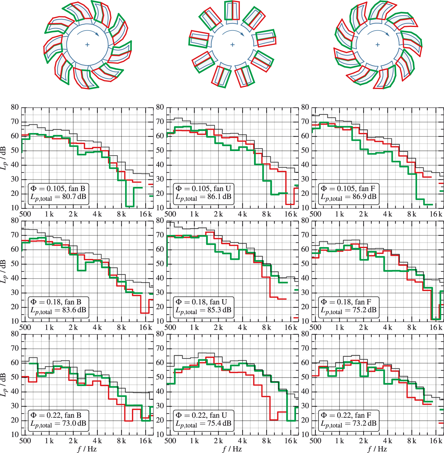
For the flow-rate coefficient of
At the design flow-rate coefficient of
The LE and TE spectra of fan B at
At the highest considered flow-rate coefficient of
Conclusion
The influence of the skew of fan blades on the noise emission has been studied based on microphone array measurements conducted with three generic axial fans. With the help of the virtual rotating array method and subsequent beamforming and deconvolution algorithms, sound maps were generated. These allowed the detailed evaluation of acoustic source mechanisms occurring on backward-skewed, unskewed, and forward-skewed fans by means of localizing major sources and generating blade LE and TE spectra.
Several noise generating mechanisms, such as turbulence ingestion, vortex shedding, and tip clearance could be identified by acoustic source mapping. Some of the phenomena observed suggest that regions of turbulence generation do not necessarily coincide with the location of related noise generation.
It has been shown that, although the forward-skewed fan has an extended operating range below the design point, the noise emission at a very low flow rate is much higher due to extensive flow separations at the LE. At a high flow rate, the unskewed fan exhibits higher noise generation at the TEs than the skewed fans.
Independent of the operation point, the noise generation at the LEs of the forward-skewed fan is shown to dominate the spectrum at certain frequency bands. This is not the case for the backward- and unskewed fans, where the dominating part depends on the flow rate. In general, TE noise is more dominant at high flow rates and at higher frequencies.
At the design flow rate, the forward-skewed fan exhibits the least noise generation. Aside from comparatively low TE noise at medium frequencies, the major differences to the other fans can be found at the lower part of the spectrum. As has been discussed, the certain identification of the phenomena occurring at low frequencies requires further experiments with adapted array geometry and data processing.
This study has shown that noise generation mechanisms that have been discussed theoretically or measured indirectly can be verified with direct acoustic measurements. As the dominant source regions differ depending on the fan geometry and the operating point, an efficient noise reduction approach necessitates accurate knowledge of the location and strength of multiple sources. With the setup at hand, more insight into aeroacoustic phenomena occurring with rotating machinery can be gained, allowing the development of tailored measures for noise reduction.
Footnotes
Declaration of conflicting interests
The author(s) declared no potential conflicts of interest with respect to the research, authorship, and/or publication of this article.
Funding
The author(s) received no financial support for the research, authorship, and/or publication of this article.