Metamaterials might be one of the breakthrough technologies needed from the aeronautic industry to achieve the more and more challenging targets set by the international authorities, especially about noise emissions. In this article, a theoretical link between Transformation Acoustics and Generalized Snell’s Law, two widely used metamaterial models, is demonstrated analytically and applied to case studies. The relevance of the connection in the aeroacoustic field is discussed along with the consequent computational advantages for numerical simulations. This is exploited to perform a simulation-based design optimization of a phase-graded metasurface acoustic lining of a 2 D duct in presence of flow. Results show promising abilities of the optimized device to modify and control the directivity of the noise emitted from the duct by means of unconventional reflections. The noise reduction in the desired direction is obtained through constructive and destructive interference, with no absorption from the boundaries.
During the last 15 years, there has been a great interest around metamaterials and their possibilities. Born in the field of electromagnetism,1 their applications rapidly spread multi-disciplinarily to, among the others, acoustics, vibrations, optics, and thermodynamics. Recently, the potential of metamaterials rose up interest among the aeronautical community for their applications in the reduction of aviation acoustic impact. Particularly promising is the capability of shaping the acoustic field given by metamaterials and metasurfaces that exploit gradients of acoustic phase delay to obtain anomalous reflection and refraction. Their ability to almost arbitrarily manipulate reflected or refracted wavefronts using subwavelength thicknesses make them ideal candidates for the development of low noise technologies for aeronautical applications, where size and weight constraints are particularly restrictive. This class of metasurfaces exploits the so–called Generalized Snell’s Law (GSL)2,3 stating that the classic reflection and refraction angles of an incoming acoustic perturbation impinging on a surface can be modified (almost) at will introducing a graded phase delay over the surface. Previous researches show several practical ways to realize this effect,4–11 achieving remarkable results in terms of subwavelength thickness and bandwidth of the devices.12,13 However, if on one hand particular attention has been paid to the development of metasurfaces operating in media at rest, very little has been done to take into account convective effects.13–18 The European project AERIALIST (AdvancEd aircRaft noIse AlLeviation devIceS using meTamaterials) aims at extending the theory of metamaterials and developing suitable numerical tools to take into account realistic aerodynamic flows.
The present work deals with a strategy for modeling, designing, and simulating a metamaterial–based device for extraordinary reflection. With this work we want to close the gap between the design methods used for phase–gradient metasurfaces (PGMS) and the well known Transformation Acoustics (TA), typically adopted in metamaterials design.19,20 In this way, the equivalent parameters of a metamaterial for extraordinary reflection are obtained in terms of density and bulk modulus , Figure 1.
From phase gradient to effective metamaterial parameters using TA. The phase delay given by a cell is modelled with equivalent density and bulk modulus, independently from the metasurface implementation.
These can be used to practically design the metamaterial by means of inverse design techniques and, in addition, avoid the need of modeling the complete microstructure in numerical simulations. An application is eventually proposed, which consists of a simple duct acoustically lined by an acoustical phase-graded metasurface in the presence of a simple uniform flow. By exploiting the unconventional reflection properties of this class of metamaterials, the metadevice is specifically designed to achieve a noise reduction inside a region arbitrarily selected within the acoustic field outside the duct. The corresponding equivalent parameters are obtained through an optimization process, allowing to easily take into account the presence of flow.
A link between GSL and standard transformation acoustics
Snell’s law (also known as Snell-Descartes law and the law of refraction) describes the relationship between incident and refraction angle of a wave when it passes through a boundary separating two different isotropic media.
Snell’s law states that the ratio of the sines of the angles of incidence and refraction is equivalent to the ratio of phase velocities in the two media, or equivalent to the reciprocal of the ratio of the indices of refraction:
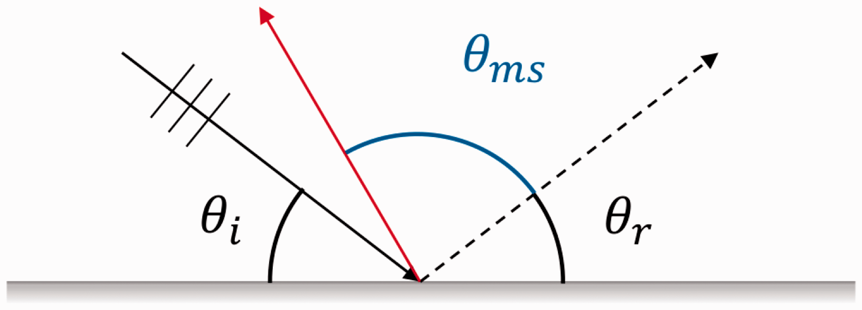
with, for each medium, θ measured from the normal of the boundary, ν the phase velocity, and n the refractive index. The law follows from Fermat’s principle of least time, which in turn is the link between ray and wave optics. Recently, a generalized version of the Snell’s Law has been presented, including the effect on the refraction/reflection angle of a nonhomogeneous phase shift induced by the refracting/reflecting boundary (Figures 2 and 3) For a monodimensional boundary, i.e. a bidimensional domain, the Generalized Snell’s Law (GSL) reads:
where the subscripts i and t indicate the incident and transmitted quantities respectively (ni and nt being the refractive indexes, equal to 1 in air) and λ is the wavelength of the incident wave. In case of a hard boundary at the interface, only reflections occur and equation (2) is hence modified as
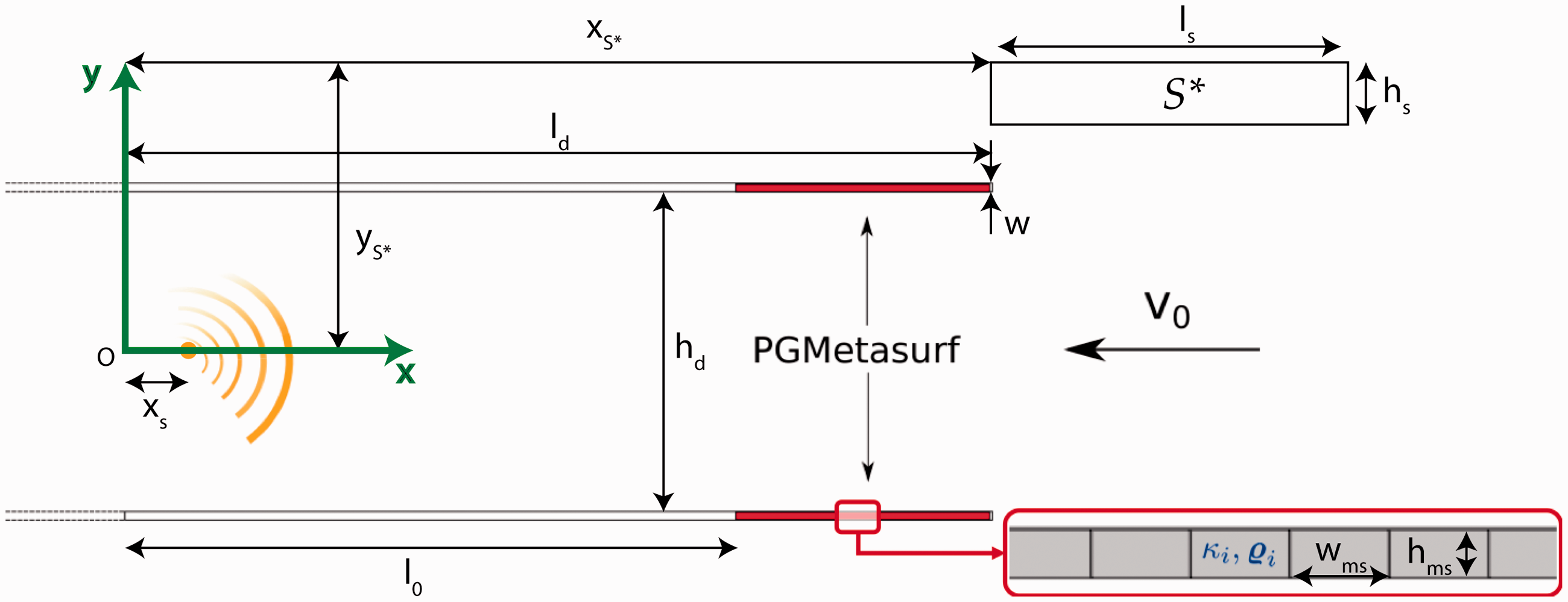
Sketch of the Snell’s Law for refraction: at the interface between two media of different refractive indices, with , the angle of refraction θ2 is less than the angle of incidence θ1, i.e. the ray in the higher-index medium is closer to the normal.
Sketch of the Generalized Snell’s Law for reflection principle: an incident (acoustic) perturbation impinges with an angle θi on a surface which adds a phase delay to the wave. The phase delay is graded along the boundary and this make the reflected angle to be changed. This behaviour can be interpreted as an extra reflection angle θms given by the phase delay gradient on the surface which adds to the standard θr.
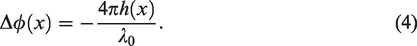
These equations link the extraordinary reflection/refraction behavior with the presence of a gradient of induced phase delay in the reflected/refracted wave by the boundary, and reduce as expected, to the traditional Snell’s law when no phase gradient (PG) is present on the interface. Several authors developed various metamaterial concepts based on this theory. First applications started in electromagnetism and optics and then also acoustic metamaterials exploiting the GSL were finally proposed, some examples were cited in the introduction. Metamaterials designed using GSL are typically periodic structures composed by a set of elementary cells of small thickness, most of so–far developed concepts are indeed classifiable as metasurfaces. The design of a metasurface for anomalous acoustic reflection usually starts with the design of the elementary cells to be used as bricks of the device, each one introducing a different phase shift in the acoustic reflected or transmitted field with respect to an acoustically hard wall; refers to the phase, evaluated at a reference position, of the acoustic field in presence of an acoustically hard wall and to the phase of the reflected wave, evaluated at the same point, when the elementary cell is positioned in place of the hard boundary. Combining the elementary units, the designer would be able to reproduce a phase gradient profile at will and hence obtain the desired local extraordinary reflection angle by discretizing in space the continuous function . Most of the literature studies the metasurfaces in a two–dimensional domain, assuming an infinite extension in the third direction of the design. We will follow this approach, keeping in mind that the extension to the three-dimensional case is straightforward, with minor modifications to the notation adopted in the following. The easiest design for an elementary cell for acoustic reflection is a waveguide for the zeroth-order mode, i.e. a hardbacked tube whose width is a fraction of the perturbation wavelength, able to carry waves with minimal loss of energy. This concept has been used by Zhu & Zou et al.,21 demonstrating numerically and experimentally the validity of the theory of acoustic phase gradient metasurfaces based on the GSL. The length of the tube h can be easily linked to the phase delay achieved, by a simple relation involving the wavelength λ0 of the acoustic perturbation under consideration and the length of the path covered by the wave, 2 h:
In the introductory section, several works regarding GSL metasurfaces have been presented, each one with its own design. However, all these different concepts are just particular ways to realize tunable phase delays. A general theory that connects Standard Transformation Acoustics (STA)19 with the phase gradient metasurface and GSL can be obtained looking at a phase delay as an acoustic mirage obtainable with a metafluid: equation (4) shows how a metasurface for extraordinary reflection can be built with a suitable distribution of waveguides of different lengths, i.e. the metasurface creates a local space–varying acoustic mirage.
Addressing the acoustic mirage in terms of Transformation Acoustics, let Ω and ω be the original and the deformed domains, the coordinates in each configuration are X and x respectively; the mapping is defined by and it is a one–to–one invertible transformation. The deformation gradient is , or in component form , hence the Jacobian of the deformation is . The polar decomposition implies where R is proper orthogonal and . The expression for the Laplacian in X in terms of derivatives in x is
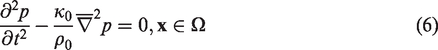
Following STA, inside the undeformed domain Ω there is a homogeneous acoustic fluid characterized by density ρ0 and bulk modulus k0; to mimic the scalar wave equation in Ω
with a metafluid occupying the deformed region ω, one obtains that it is replicated by the equation
where the bulk modulus and the inertia tensor are
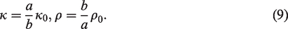
In the simple case of a one–dimensional mirage, to define the metafluid properties, the desired thickness (> 0) of the metasurface must be set, hence, following the above procedure and Figure 4 we obtain
Acoustic mirage representation. The darker domain of length a is able to mimic the acoustic behaviour of the domain of length b, being characterized by a tailored density ρ and bulk modulus κ. (Reprinted with permission from.20Copyright 2009, Acoustic Society of America.).
Hence, a link between the desired from a metamaterial and its characterizing parameters ρ, κ and thickness a is established, demonstrating the extension of the STA to model GSL–based metamaterials and metasurfaces: as usual n different cells can be defined dividing the interval and their TA model derived as said before.
GSL–based metasurface with transformation acoustics
The above-stated connection between GSL and STA can be extended from the discrete (single bricks), as established in equation (8) to the continuum (a whole metasurface). Once the desired phase delay profile has been designed from equation (3), the corresponding TA metacontinuum can be defined with a limit approach from equation (9): thinking of an infinite number of reference waveguides with an infinitesimal width, each one satisfying equation (4), a continuous relation for and is obtained as
where x is the direction in which the metasurface imposes a phase gradient. This implies that all the design strategies that have been developed inside the STA framework, and all the concepts able to change the effective density and speed of sound of a domain, e.g., pentamode materials, can be adopted for the design of a GSL–based metamaterial. Several works can be found in literature14–18 in which corrections for STA-designed metafluids are proposed to take into account the effects of the aerodynamic convection on acoustic propagation that would otherwise make the metadevices ineffective in the presence of flow. These corrections are hence made available by the theoretical link described above also for the design of phase-graded GSL-based metamaterials.
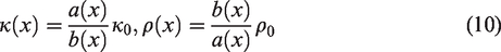
It is worth noting that the coordinate transformation set for the continuous case is a space–varying 1-D transformation that maps a longer segment into a shorter one and it is not a 2 D mapping from an arbitrarily shaped region into a flat and thinner one. This is necessary to preserve the nature of the phenomenon that occurs for the discrete metasurface, as it is made by a sequence of separate waveguides of different lengths, each one imposing a different phase delay. To show the stated equivalence, a typical case used in the study of PGMS is considered, i.e. the manipulation of the reflected wavefront from a metasurface. For the case of a metasurface imparting an extra reflection angle of 60° when impinged by a normal plane wave (), the GSL states that along the surface a phase delay gradient of must be obtained. Hence, b(x) from equation (4) is , varying between 0 and in giving . In Figure 5 the scattered pressures from a GSL metasurface made by straight waveguide or its STA models, continuum and discrete, are presented, confirming the validity of the proposed link.
Scattered pressures ps from a GSL metasurface impinged normally by a plane wave. The surface is designed to obtain a reflection angle . Figures (a), (b) and (c) show respectively the solution for a waveguide–based design, a discrete and a continuous STA design. (a) Wave guides, (b) discrete metafluid and (c) continuous metafluid.
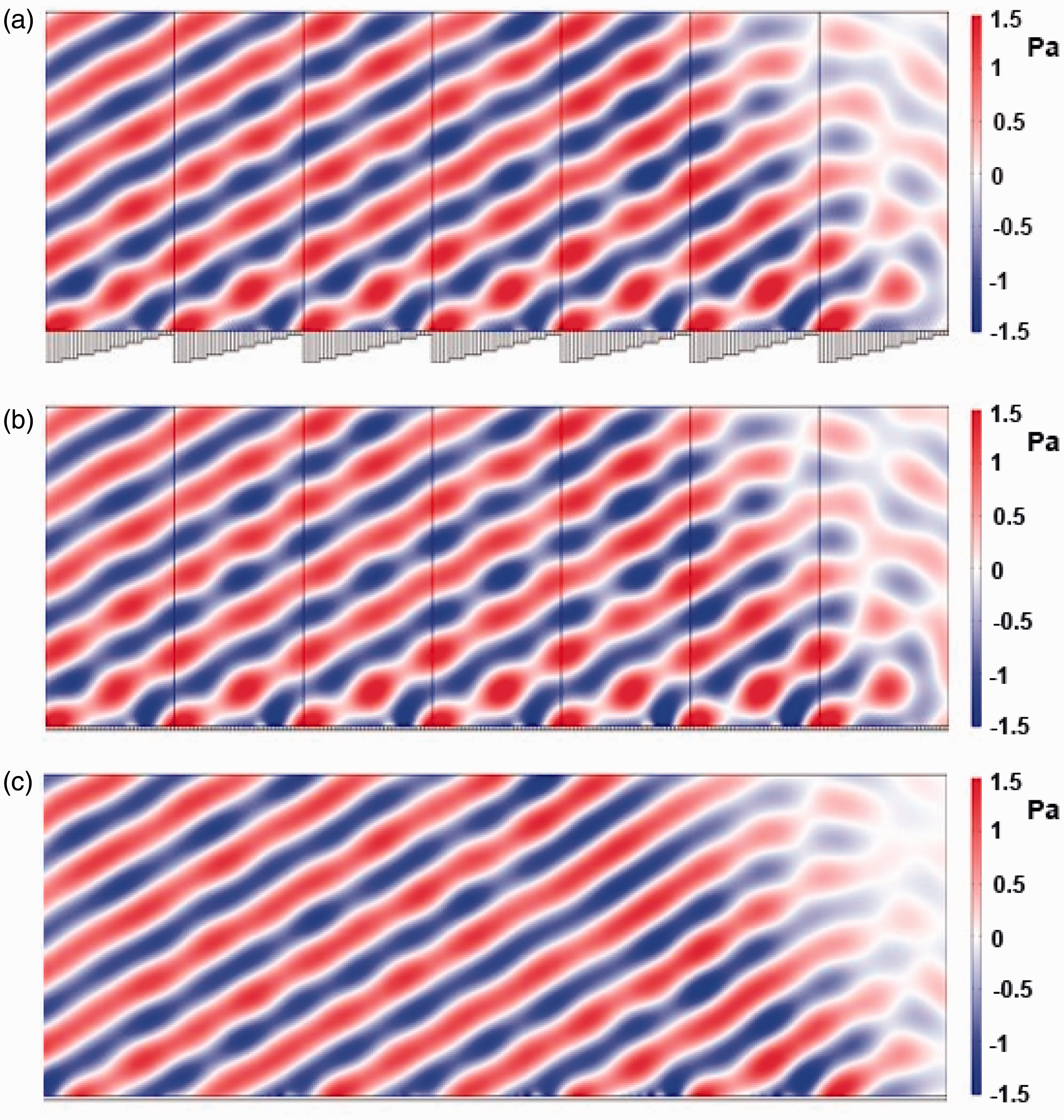
In order to show the equivalence in a more general case, the inverse process, i.e. obtaining equivalent waveguide starting from an arbitrary distribution of discrete metafluids, was addressed for the case of a monopole placed within a duct partially lined by PGMS. The comparison between the discrete metafluid and waveguide configuration in Figure 6, shows, although qualitatively, an excellent agreement between the two approaches, confirming their equivalence.
Comparison between the acoustic potential field in case of metasurface based on discrete metafluid and equivalent waveguides. (a) Discrete metafluid and (b) wave guides.
Optimized design of a metasurface
At the design level, there are several advantages that can be obtained through the use of the theoretical approach described in the previous section, especially in the context of simulation–based conceptual optimization where the minimization of computational effort plays a fundamental role. The use of the equivalent metafluid for the design of phase gradient metasurfaces requires in fact the identification of a small number of parameters without the difficulties associated with the implementation of specific, sometimes very complex, microstructures necessary in numerical simulations. In addition, the geometry of the cells remains unchanged during the optimization process and does not require the regeneration of the corresponding mesh at each iteration. In this section, the ability of the presented method to model phase–graded metadevices is exploited to address the design of acoustic treatment of (part of) a simple bidimensional duct in the presence of a uniform flow.
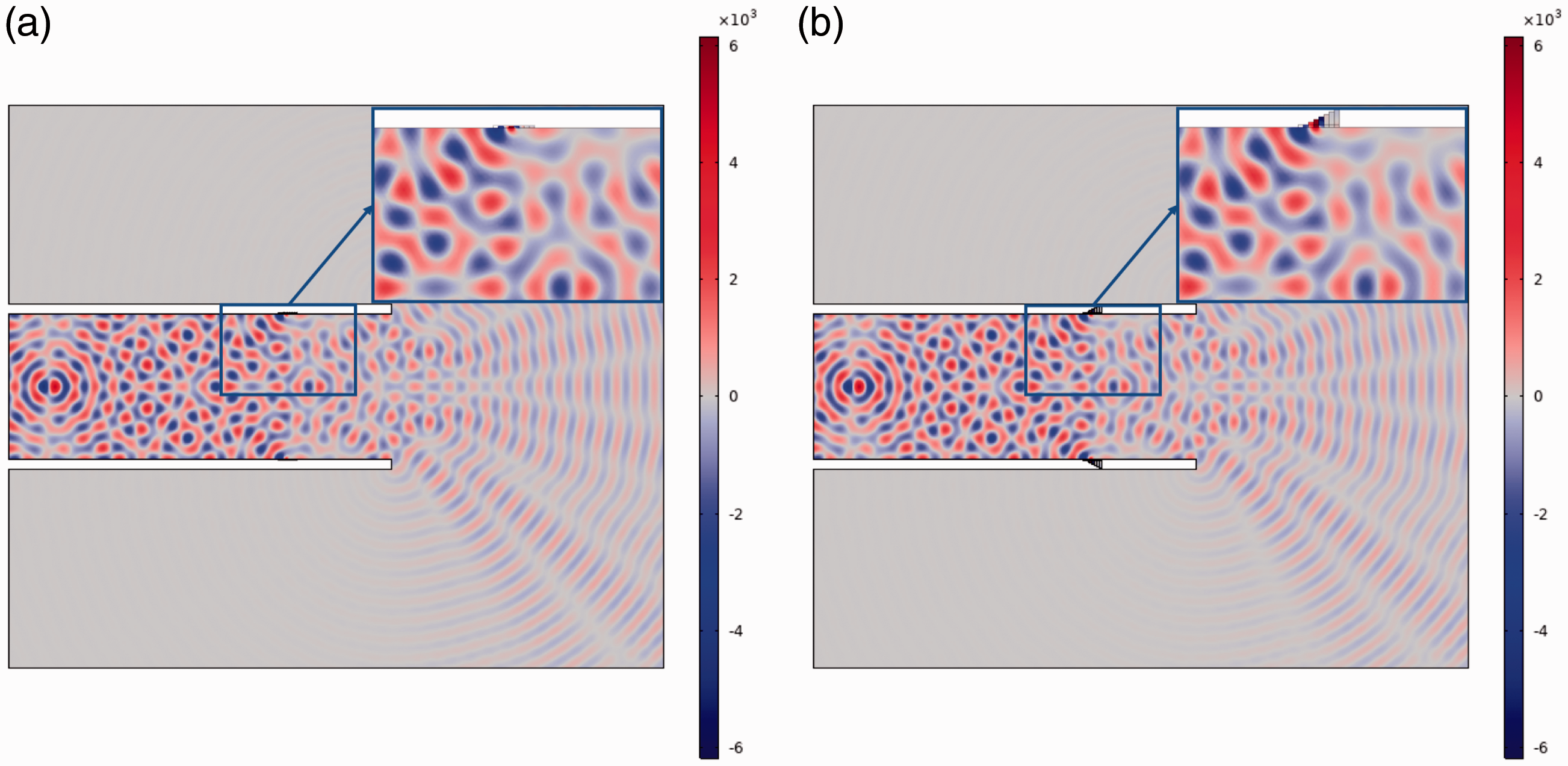
With this work, we want to explore the possibility of using phase–graded metasurfaces for the design of devices of interest in the aeronautical field, such as the acoustic treatments for engine nacelles, of which the proposed application represents, albeit in a considerably simplified form, a schematization. In the proposed approach, the parameters of the equivalent metafluid are obtained through an optimization process aimed at obtaining the desired effect, hereinafter called target behavior, in the acoustic field. For the present application, the target behavior consists of minimizing the noise level within a region contained in the acoustic field outside the duct, using a monopole located inside the duct as an acoustic source. A sketch of the duct geometry is shown in Figure 7, including the acoustic source, the metasurfaces and the rectangular region ( in the figure) used to define the target behavior. The duct is terminated with a radiation condition on one side, simulating a semi-infinite duct. Additional information regarding the numerical set-up is reported in the Results section. For simplicity, the flow entering into the duct is assumed uniform everywhere; however, it is worth noting that this is not a limitation as any complex flow can be used as an aerodynamic background with the present method. The metasurfaces, positioned both in the upper and lower part of the duct, close to the flow inlet section, consist of two sequences of unitary cells separated by rigid walls. The i–th cell hosts an (equivalent) metafluid defined in terms of equivalent bulk modulus κi and density ρi. As previously noted, equation (9) states that the impedance of the equivalent medium equals that of the hosting fluid. Since only one of the two equivalent parameters can be freely set in the unit cell, for the present application the bulk modulus has been chosen as the independent parameter. Finally, the appropriate distribution of speeds of sound in the cells is determined through a simulation-based optimization, the details of which are presented in the following paragraph.
Sketch of the 2 D duct geometry, including the acoustic source (in yellow), an enlarged view of the elementary cells of one of the phase–graded metasurfaces based on discrete metafluid and the rectangular subdomain used to define the objective function in the optimization process.
Optimization
A general single–objective unconstrained optimization problem can be formalized as follows:
where x is the vector of Nx design variables bounded by and , y is the vector of the parameters, while is the objective–function to be maximized or minimized. The design variables for the current application are the speeds of sound of the equivalent discrete metafluid within the Ncell unit cells of the metasurfaces. In order to cover a phase-delay range of , each design variable must fall within a suitable range defined by the values and , the latter obtained taking into account the relationship between sound speed and phase shift provided by combining equations (4) and (9). The objective function is defined as
where
represents the difference between Sound Pressure Levels in the reference case of full hard walls (HW) and in the presence of PG metasurfaces (MS). Acoustic pressure values are obtained in the frequency domain for a monochromatic acoustic source from direct linear losses acoustic simulations using the commercial Finite Element Method (FEM) solver Comsol Multiphysics®. The governing equation of acoustic perturbations in a barotropic and inviscid fluid, and an irrotational flow, in terms of acoustic potential reads
where indicates Fourier transformation, the acoustic source term, whereas and represent mean flow and density respectively. This equation is equivalent to the set of linearized Euler equations under the given hypotheses. In the case of uniform mean flow and uniform mean density , equation (14) reduces to the convective Helmholtz equation
where is the acoustic wave number and the aerodynamic Mach number. Once the acoustic potential is known, the acoustic pressure can be calculated through the Bernoulli’s theorem
Results
The metasurface is optimized for a design frequency (λ0=0.1 m), its thickness is defined to be 0.00625 m () and each cell is wide. The duct internal channel height is hd = 0.775 m (7.75λ0) with walls thickness w = 0.0125 m (λ0/8). Its length inside the calculation domain is ld = 2.04 m () and it is truncated by a non-reflective radiation condition at one side (left in Figure 7). Both the upper and lower metasurface are composed of 48 cells, being the first ones of both placed at l0 = 1.44 m from the origin. The duct is vertically centered inside a rectangular region of width and height , representative of the exterior unbounded domain, where the same non-reflective radiation condition is applied. The left boundary of this box coincides with the left termination of the duct. The area over which the objective function is evaluated with equation (12) is a rectangular subdomain of width = 1 m () and height = 0.2 m (), its upper left corner is placed in = 2 m = 0.8 m, using the frame of reference in Figure 7 which is vertically centered in the calculation domain and aligned with its left boundary.
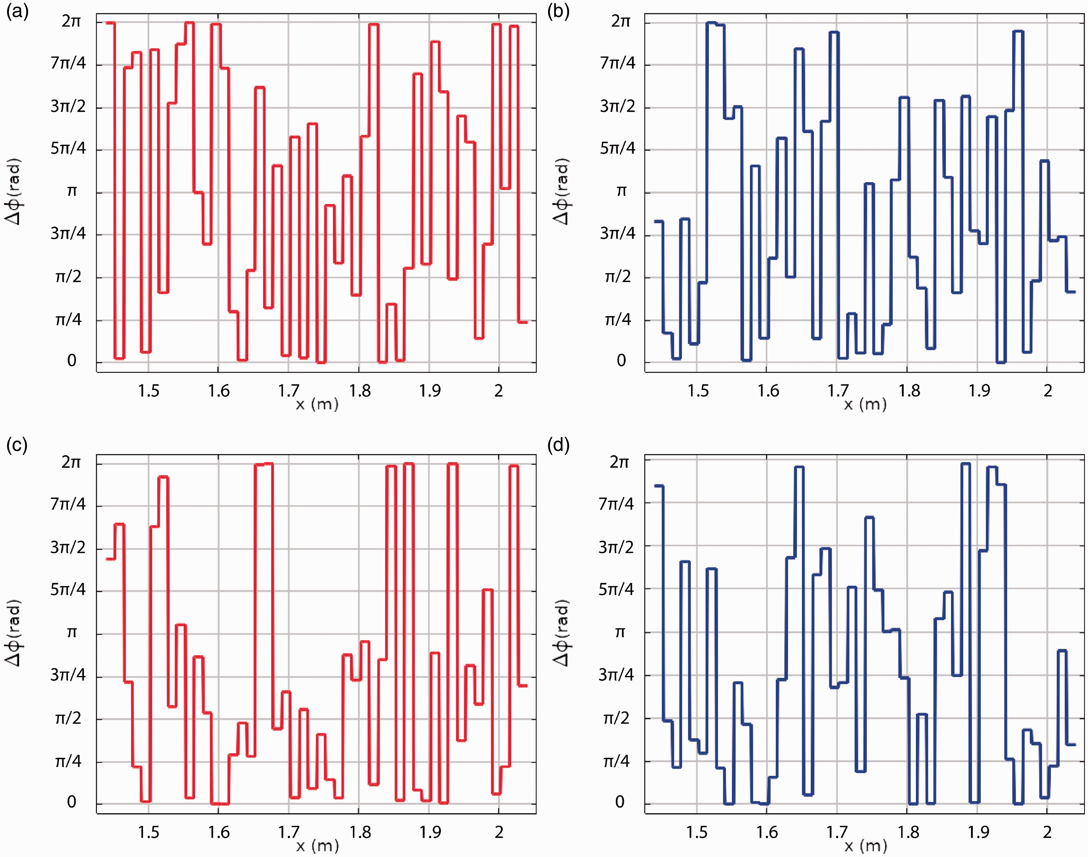
The maximization of the objective function equation (12) is achieved through a standard Particle Swarm Optimization (PSO) algorithm,* originally introduced by Kennedy and Eberhart.22 PSO is based on the social-behavior metaphor of a flock of birds or a swarm of bees searching for food, and belongs to the class of heuristic algorithms for evolutionary derivative-free global optimization. For the present application, Ndv = 96 is the number of design variables, i.e. the number of unit cells, while Nppdv = 10 is the number of particles per design variable, which lead to number of function evaluations (simulations) per iteration. The final distributions of of the equivalent metafluids are depicted in Figure 8 for both the cases, in a quiescent fluid and with flow at M = 0.3.
Final distribution of of the equivalent metafluids. The optimized phase delays for the upper and lower metasurfaces at M = 0.0 can be found in 8(a) and 8(b) respectively, while the corresponding for the case M = 0.3 are depicted in 8(c) and 8(d). (a) Lower MS - M = 0.0, (b) Upper MS - M = 0.0, (c) Lower MS - M = 0.3 and (d) Upper MS - M = 0.3.
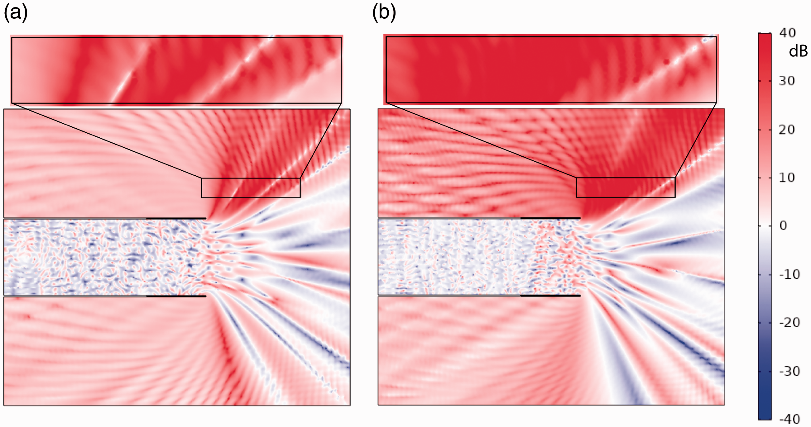
Results are obtained for a monochromatic acoustic perturbation at the design frequency f0 emitted by the monopole acoustic source of unitary mass flow rate, , placed inside the duct at xs = 0.244 m away from the origin. It is worth noting that the intensity of the source can be chosen arbitrarily as the simulations have been performed under the assumption of linear acoustics. Furthermore, the results are presented in terms of differential values with respect to the reference, i.e. non lined case, hence non depending on the intensity of the acoustic source. Figure 9 shows the results of the optimizations in terms of (as defined in equation (13)) for the static case (no flow) and for a uniform flow at Mach = 0.3. As can be observed, the phase delays of the optima have a complex and discontinuous pattern. In both cases, the optimizer is able to find a solution that obtains a significant reduction of the SPL in part of the selected region, also in presence of flow. The effect is obtained by means of energy redistribution, through the combination of constructive and destructive interference. In fact, there is no absorption from the boundaries of the duct, which are acoustically perfectly reflective (acoustically hard), nor inside the metafluid. The only effect of the metafluid cells is to change the phase of the reflected wave according to their local parameters. The distribution of the optimized phase delays, in particular its gradient as stated in equation (3), steers the overall sound emission from the duct satisfying the requirement stated in the objective function. This unconventional reflection effect allows reducing the SPL inside of more than 30 dB. With reference to the same figure, it can be seen that the SPL reduction is not limited to the rectangular subdomain used to define the objective function in the optimization process, but extends in a wider region above the duct, for both cases at M = 0 and M = 0.3, effectively changing the duct directivity. This value is however not fully representative of the achievable noise reduction of this type of metadevice. The simplifying assumptions made on the underlying aerodynamic flow make deeper investigation needed, coupling the acoustic solver with more realistic flow solutions from e.g. RANS or LES models in order to investigate the effect of boundary layers and vorticity. Depending on the destination of the lining, more accurate geometries of the hosting device should be used in the simulations and special attention should be paid on the acoustic sources characterizing the incident field in operational conditions. All these aspects may contribute to change the optimum both in the domain, i.e. the optimal phase gradient, and in the codomain, i.e. the noise reduction in terms of dB. Moreover, the results presented in this article deals with optimization for one specific frequency and Mach number as only aimed at testing the methodology capabilities. This aspect is addressed more in detail in the Conclusion section.
(see equation (13)) for the static case and in the presence of a uniform flow at M = 0.3, includind a magnified view of the maximization area. (a) M = 0.0, (b) M = 0.3.
The required acoustic masking effect is similar to that observed in the case of engine nacelles equipped with a negative scarf,23 in which the greater extension of the lower lip of the inlet compared to the upper lip creates a shield effect for noise directed towards the ground. Despite the remarkable performance in terms of noise reduction, it is known that the negative scarf introduces a weight penalty which causes a slight reduction of the aircraft performance. The phase–graded metasurfaces, therefore, represent a potential candidate for realizing the so-called virtual scarfing, as already observed in Palma,24 in which the desired masking effect is obtained without introducing changes to the layout of the engine nacelle.
Conclusions
A strategy for modeling, designing and simulating a metamaterial–based device for extraordinary reflection exploiting the Generalized Snell’s Law is presented. A link between GSL and TA is established, which allows looking at a phase delay as an acoustic mirage obtainable with an equivalent metafluid, also avoiding the burden of modeling specific microstructures in numerical simulations. The corresponding equivalent density and bulk modulus can be used to design phase–graded metamaterials by means of inverse design techniques, exploiting concepts developed within the metafluid theory and closing the gap between these two widely used metamaterial design theories. The methodology proposed in the present article is applicable when it is possible to effectively model the metasurface effect just as a phase shift, and nonlinear phenomena, e.g. involving thermal and viscous losses, can be neglected. This approach also allows taking easily into account flow effects, a feature that makes it a particularly attractive tool for the conceptual design of devices of interest in the aeronautical field. Taking advantage of the proposed framework, a simulation–based optimization procedure is used to address the conceptual design of phase–graded metasurfaces for the acoustic lining of a 2 D duct in the presence of a simple uniform flow aimed at reducing the sound pressure level inside an arbitrarily selected region within the acoustic field. It is found that the optimized PMGSs allow having an extra degree of freedom in the design of acoustic treatments for noise reduction, which can be exploited to obtain significant changes of the acoustic directivity without modifying the geometry of the duct. It is important to stress that the results obtained for the virtual scarfing are preliminary and based on ideality assumptions. The distribution of phase delays resulting from the optimization procedure would be clearly affected and changed by the introduction of more realistic and complex flow conditions. The optimization procedure provides the optimal phase gradient for the required objective. The designer would hence tailor its implementation of PGMS to follow the optimal phase gradient profile.
In this work, the optimization has been performed for a single frequency and Mach number and no hint on the off-design behavior is given. The method can be, however, integrated into a robust optimization procedure, taking into account uncertainties on the operating conditions as, for example, a frequency band or a range of Mach numbers. The resulting phase gradient would be optimum in a broader sense, probably giving a reduced peak performance with respect to the nonrobust solution, but minimizing the maximum relative regret under all the considered conditions. Another path is to obtain a deterministic optimum phase gradient dynamic, from several optimizations for different operational conditions. The issue is hence moved to the possibility to find a design, or a combination of more, for the elementary cells capable to replicate that dynamic. This nontrivial task can be, for example, addressed again via optimization, as in Palma et al.12 Regardless of the method adopted, however, its success is not guaranteed apriori as it strongly depends on the specific design.
Both the development proposed to integrate the effect of different frequencies and Mach numbers in the design would add robustness to the acoustic performances of the device in a broader range of operational conditions, at the cost of a significantly increased computational effort with respect to a classic design procedure.
Footnotes
Declaration of conflicting interests
The author(s) declared no potential conflicts of interest with respect to the research, authorship, and/or publication of this article.
Funding
The author(s) disclosed receipt of the following financial support for the research, authorship, and/or publication of this article: This research is partially supported by the EU funded project AERIALIST (Grant agreement ID: 723367).
ORCID iDs
Giorgio Palma
Lorenzo Burghignoli
Notes
* The update at iteration k + 1 of the design point identified by the i-th individual of the swarm is given by
where χ is a constriction factor, c1 and c2 are the the social and cognitive learning rate, and are random numbers in the range [0,1] and pi and g are the personal best of the i-th particle and the global best of the swarm, respectively.
References
1.
WalserRM. Electromagnetic metamaterials. In: Lakhtakia A, Weiglhofer WS and Hodgkinson IJ (eds) Complex Mediums II: beyond linear isotropic dielectrics, volume 4467. Bellingham: International Society for Optics and Photonics, SPIE, pp.1–15.
2.
YuNGenevetPKatsMA, et al.
Light propagation with phase discontinuities: Generalized laws of reflection and refraction. Science2011;
334: 333–337.
3.
AietaFKabiriAGenevetP, et al.
Reflection and refraction of light from metasurfaces with phase discontinuities. J Nanophoton2012;
6: 063532–063539.
4.
LiangZLiJ.Extreme acoustic metamaterial by coiling up space. Phys Rev Lett2012;
108: 114301.
5.
LiYLiangBGuZ, et al.
Reflected wavefront manipulation based on ultrathin planar acoustic metasurfaces. Sci Rep2013;
3: 2546.
6.
LiYJiangXLiR, et al.
Experimental realization of full control of reflected waves with subwavelength acoustic metasurfaces. Phys Rev Applied2014;
2: 064002.
7.
TangKQiuCKeM, et al.
Anomalous refraction of airborne sound through ultrathin metasurfaces. Sci Rep2014;
4: 6517. DOI:10.1038/srep06517.
8.
WangWXieYKonnekerA, et al.
Design and demonstration of broadband thin planar diffractive acoustic lenses. Appl Phys Lett2014;
105: 101904.
9.
XieYWangWChenH, et al.
Wavefront modulation and subwavelength diffractive acoustics with an acoustic metasurface. Nat Commun2014;
5: 5553.
10.
ZhuYFFanXDLiangB, et al.
Multi-frequency acoustic metasurface for extraordinary reflection and sound focusing. AIP Adv2016;
6: 121702.
PalmaGCioffiICentracchioF, et al. Steering of acoustic reflection from metasurfaces through numerical optimization. In: 25th AIAA/CEAS Aeroacoustics Conference. Reston, Virginia: American Institute of Aeronautics and Astronautics, 2019.
13.
IemmaUPalmaG. Optimization of metasurfaces for the design of noise trapping metadevices. In: Proceedings of the 26th international congress on sound and vibration. Montreal, Canada: Canadian Acoustical Association, 2019.
14.
García-MecaCCarloniSBarcelóC, et al.
Analogue transformations in physics and their application to acoustics. Sci Rep2013;
3: 2009.
15.
IemmaU.Theoretical and numerical modeling of acoustic metamaterials for aeroacoustic applications. Aerospace2016;
3: 15.
16.
IemmaUPalmaG. Aeroacoustic design of metafluid devices. In. 24th international congress on sound and vibration2017. ICSV 2017. London: IIAV, 2017.
17.
IemmaUPalmaG.On the use of the analogue transformation acoustics in aeroacoustics. Math Probl Eng2017;
2017: 8981731.
18.
IemmaUPalmaG.Convective correction of metafluid devices based on TAylor transformation. J Sound Vibr2019;
443: 238–252.
19.
NorrisAN.Acoustic cloaking theory. Proc R Soc A2008;
464: 2411–2434.
ZhuYFZouXYLiRQ, et al.
Dispersionless manipulation of reflected acoustic wavefront by subwavelength corrugated surface. Sci Rep2015;
5: 10966.
22.
KennedyJEberhartR. Particle swarm optimization. In: Proceedings of ICNN’95 – international conference on neural networks, volume 4. pp. 1942–1948, 1995.
23.
NangiaRKPalmerME. Negatively scarfed inlets for acoustic reduction, aerodynamic performance assessment. In: 38th aerospace sciences meeting and exhibit. Reston, VA: American Institute of Aeronautics and Astronautics, 2000.
24.
PalmaGMaoHBurghignoliL, et al.
Acoustic metamaterials in aeronautics. Appl Sci2018;
8: 971.