



Abstract
We compare medium and high fidelity numerical simulations to experiments conducted on low Reynolds number rotors typical of small scale Unmanned Aircraft Systems (UAS). We first show that these numerical approaches provide reasonable estimates of the aerodynamic performance and farfield tonal noise and hence apply them for the investigation of the influence of solidity ratio on the aerodynamics and acoustics of small scale rotors operating under hovering, iso-thrust conditions. We show that while solidity ratio has a weak impact on aerodynamic performance, it may help drastically reduce farfield tonal noise. This reduction is however found to depend on the interplay between thickness and loading noise such that increasing the solidity by increasing the number of blades at constant blades’ aspect ratio or by decreasing the blades’ aspect ratio keeping the number of blades constant may yield very different, sometimes opposite, trends.
Introduction
These three past decades have seen the emergence of small size unmanned air systems (UAS) together with the advent of micro-technologies in the 90’s. Due to their versatility and operability at relatively low cost, small UAS are now increasingly used in a very wide range of applications, both in civilian and military fields. Examples include, but are not limited to, atmospheric probing, space exploration, package delivery, surveillance and cinema video production. In some specific applications like in the military field, the noise generated by UAS may be an important issue for stealth operation, with the propulsion system (propellers and/or rotors) producing large tonal noise at the blade passing frequency (BPF). A typical example is that of a vertical take off and landing (VTOL) vehicle performing observation under hovering conditions. Furthermore, other applications require that UAS be operated in close proximity to populated areas and noise regulations from aviation agencies are expected to become more stringent in a very near future. It is hence compulsory to rapidly gain knowledge on noise sources of small UAS and ultimately develop efficient and silent rotors that comply with regulations and stealth requirements.
The investigation of noise generation from rotors and propellers is not a new field of research but most studies conducted on this topic these past decades are mainly concerned with helicopters and aircraft propellers/rotors. Early works have shown that helicopter blades generate two types of noise, namely tonal noise (or discrete-frequency noise) and broadband noise. 1 Tonal noise is intrinsically associated with blade rotation, i.e. with the motion of the blades in the observer reference frame. It has four principal components. 1 First, the thickness noise, which results from the displacement of fluid by the rotating blades. Second, the steady loading noise, which results from the pressure force generated by the rotor on the fluid. Third, the blade vortex interaction (BVI) noise generated by the interaction of the tip vortex from one blade with the following blades of the rotor, typically observed in forward flight of helicopters. Finally, the high-speed impulsive noise associated with shocks and transonic flow around the blades. Broadband noise typically arises from five different sources:2,3,4 the natural unsteadiness of the boundary layer (typically observed when the boundary layer separates at low Reynolds numbers, for example), the ingestion of turbulent structures by the rotor, the interaction of the turbulent wake behind one blade with the following one, the interaction of the turbulent boundary layer developing on the blade with its trailing edge and the interaction between wake structures. All except the latter can be considered as airfoil self noise, together with airfoil tonal noise that can be produced by the occurence of aeroacoustic feedback loop, for example.
Significant efforts have also been made to understand noise sources of aircraft propellers,5–8 which, conversely to helicopters (except in ascending and descending flight) typically operate under axial flow conditions and usually feature more than two blades. Nevertheless, aircraft propellers and helicopter rotors share some similarities in their operating conditions, with comparable rotation speeds, characteristic Reynolds and Mach numbers. Common features hence exist in the generation of noise with sources of tonal and broadband noise described above. Despite such similarities, propellers may be subjected to additional interaction noise resulting from the wake of a pylon impinging the blades in pusher configuration 9 and from the wake of the fore propeller impinging the aft propeller (referred to as rotors in some cases) in counter-rotating open rotor (CROR) configurations,10,11 for example. In the latter case, wake-blade interaction usually comprises two components: the tip-vortex interaction noise and the potential-field interaction noise. 12 Furthermore, the larger number of blades may lead to more complex constructive/destructive interferences between blade sources.
While in some cases small size UAS may have similar overall architecture to larger aircraft and helicopters, they fundamentally differ in their operating conditions and characteritistic Reynolds and Mach numbers. Small size UAS propulsion sets typically operate at tip Mach numbers of the order of 0.2 and Reynolds numbers of the order of 105 where the boundary layer may undergo laminar separation, laminar-to-turbulent transition and reattachment, leading to the formation of a so-called laminar separation bubble (LSB). The LSB over an airfoil is known to be highly sensitive to freestream conditions which renders comparison between different experiments (i.e. from different facilities) and simulations challenging. 13 It is unknown whether this is the case on a rotating blade, where rotational accelerations may affect the scenario (separation, transition, reattachment) that leads to the formation of the LSB. It is thus crucial to (i) analyze the aerodynamics of rotors in this range of Mach (0.2) and Reynolds numbers (104−105), (ii) generate experimental datasets from different facilities to evaluate the sensitivity of the flow to surrounding conditions and (iii) assess the accuracy of numerical methods in such transitional regime. Furthermore, due to the strong dependency of noise sources to the dynamics of the boundary layer (for example through transition and resulting broadband trailing edge noise, which in turn also affects airfoil loads and hence tonal noise), extending this analysis to aeroacoustics is equally important. In addition to significant differences in characteristic Reynolds numbers, small UAS operate at lower Mach numbers than helicopters and aircraft and hence typical high-speed noise sources described previously become irrelevant and the relative contribution of different sources (e.g. thickness and loading) may drastically change. Finally, some UAS architectures (e.g. multi-copters) involve multiple rotors in coaxial or tandem arrangements which may induce additional interaction noise than those typically observed at larger scales, again coupled with low Reynolds number effects.
Noise generation from small isolated rotors was recently investigated experimentally by Zawodny et al, 14 Gojon et al, 15 Casalino et al 16 and numerically by Zawodny et al, 14 Jo et al, 17 Mankbadi et al 3 and Casalino et al, 16 for example. Overall, it was shown that the farfield spectrum is characterized by tonal noise at the BPF and harmonics and broadband noise at mid- and high-frequency. While the directivity of the BPF constantly exhibits a dipole-like pattern, that of its first harmonic may transition from monopole-like to dipole-like patterns depending on the geometrical/operating parameters like the number of blades and the rotation speed. On the other hand, the high frequency broadband noise exhibits a dipole-like pattern with lowest sound pressure levels (SPL) aligned with the blade trailing edge.
Further efforts were provided by Serré et al 18 and Li Volsi et al 19 to optimize small scale rotors in view of reducing the aeroacoustic footprint. This goal can be achieved by different means, focusing on specific components of the overall SPL. For example, increasing the number of blades leads to a decrease in rotational speed (to achieve a given target thrust) which helps reduce steady loading noise but may on the other hand promote broadband noise through increased blade wake interactions.15,17 On the other hand, wavy leading edges and serrated trailing edges may help reduce broadband noise arising from blade wake interactions and trailing edge turbulence (e.g. Serré et al 2019; 18 Pang et al 20 ).
In addition to isolated rotors, several works focused on rotors in interaction with their surroundings. Lee and Lee 21 recently reported numerical results on the noise generated by four interacting rotors. They have shown that for small rotor-to-rotor spacings, an upwash flow develops in the center of the multi-rotor configuration, together with a low pressure region that tends to deviate each rotor wake from a purely (unskewed) helical pattern. The resulting flowfield is highly unsteady with wake instabilities developing faster than for isolated rotors. This contributes to increasing rotor noise, in addition to a reduction in aerodynamic performance. Zawodny et al 22 analyzed noise generation from rotor-airframe interactions. Their results reveal prominent, additional tonal noise resulting from rotor wake impingement on the airframe. Corresponding SPL are highly directional and rapidly decay with increasing rotor-airframe spacings. More complex configurations with multiple rotors and airframes were investigated by Sinibaldi and Marino, 23 Intaratep et al, 24 Yoon et al 25 and Tinney and Sirohi, 26 among others.
While these studies provided valuable insight into prominent mechanisms responsible for noise generation on small scale VTOL UAS, current knowledge on this matter is still limited. First, as previously outlined, the sensitivity of the flow to freestream conditions observed for airfoils at Reynolds number on the order of 105 and the difficulty to predict the flow and resulting aerodynamic loads using numerical approaches raise the question of the reproducibility of experimental results from different rotor test benches (further noting that measurements at small scales typically suffer from larger uncertainties than measurements at large scales) and the relevancy of low, medium, and high-fidelity numerical methods in such configurations. The present paper thus seeks to provide the reader with experimental and numerical data and to evaluate the accuracy of a non-linear vortex lattice/particle method (NVLM) and implicit large eddy simulations (iLES). In particular, the NVLM is a relatively recent enhancement of the (linear) VLM which allows to partially account for laminar separation, laminar-to-turbulent transition and reattachement at relatively low-cost and its use remains sparse for low Reynolds number aeroacoustic problems.21,27 Moreover, we use these combined datasets to evaluate the influence of rotor solidity ratio on aerodynamic performance and noise generation. The effect of solidity ratio is virtually unexplored for small scale rotors where the relative importance of thickness and loading noise may significantly differ from that typically observed at larger scales.
The remainder of the paper is as follows. First the methodology is described with details on the rotor geometry, experimental setup, NVLM and iLES. Second the aerodynamics and aeroacoustics of a two-bladed rotor are analyzed in light of both experimental and numerical results. Third, the influence of solidity ratio on aerodynamics and aeroacoustics is investigated using both experimental and numerical results. Finally some conclusions are drawn and perspectives for future work are given.
Methodology
Rotors geometry
We consider small scale rotors operating under hovering flight conditions, with characteristic Reynolds and Mach numbers on the order of 105 and 0.2, respectively. Note that the Reynolds and Mach numbers are here based on the chord length and local blade velocity at 80% of the radius. All rotors have constant chord length and constant 10° pitch blades with NACA0012 section profile and only the number of blades and blades’ aspect ratio are varied, leading to rotors with different solidity ratios σ = Nc/πR, where N, c and R are the number of blades, the blade chord length and the rotor radius, respectively.
Experiments
The rotors are 3D-printed using ‘Form 2’ stereolithography 3D printer and the glass reinforced ‘Rigid’ white resin from Formlabs. They are driven by means of a Faulhaber 3274G024BP4 3692 electric brushless motor, which has low noise emissions as compared to conventional off-the-shelf motors. Real time revolution per minute (RPM) are directly given by the associated motion controleur MC5010 which provides a precise speed control.
Thrust and torque measurements are performed using two different test benches. The first one includes a six-axis ATI Nano17 load cell placed beneath the motor, as depicted on Figure 1. The second one is a pendulum type test bench consisting of two 10N S100 load cells from Strain Measurement Devices (SMD) for thrust T and torque Q measurements. Time signals of T and Q (and other quantities like RPM, pressure and temperature) are acquired at a frequency of 2 kHz during 16 s after initial transients have decayed (i.e. typically 30 s after the RPM was changed). Time-averaging is performed over the whole 16 s time window, which ensures statistical convergence. Photography of the experimental setup in the anechoic room.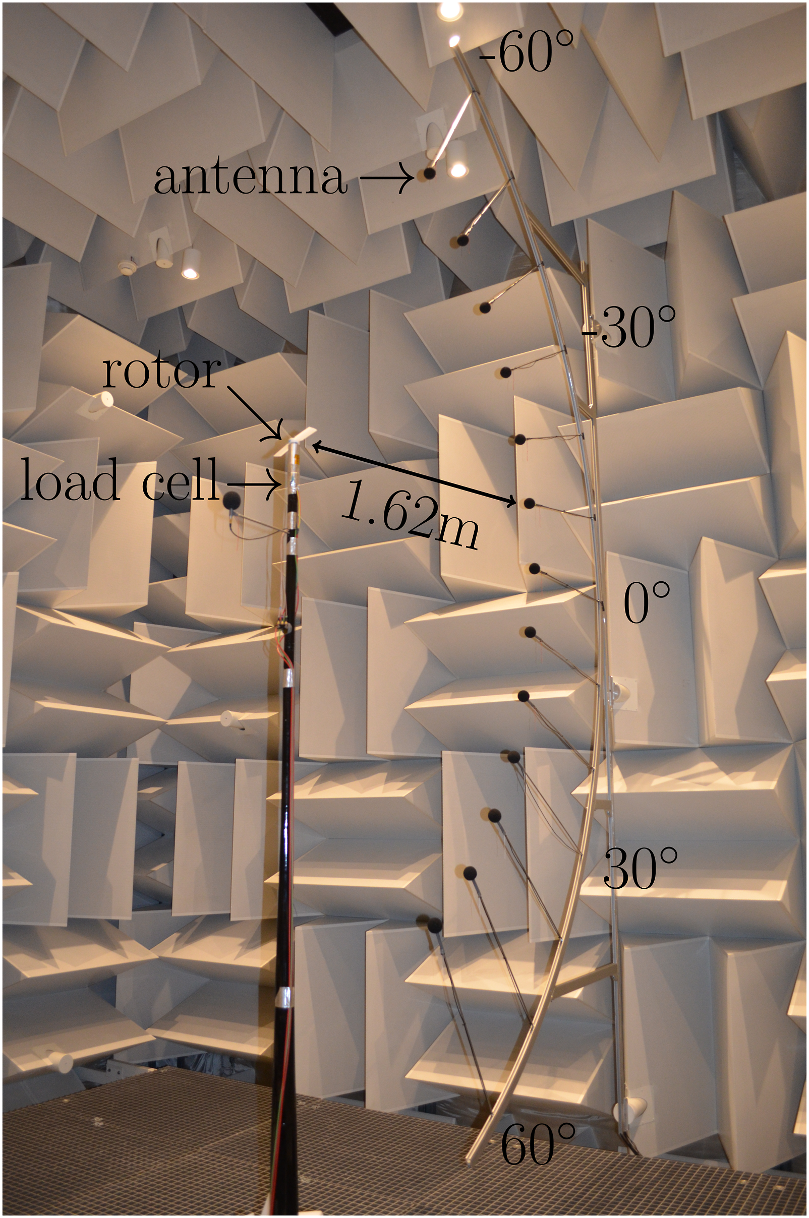
Acoustic measurements are conducted using the first test bench previously shown in Figure 1. The test bench is placed in an anechoic room, which is acoustically treated in the frequency range 80 Hz–16,000 Hz and has wedge-tip to wedge-tip dimensions of 5.02 m long, 5.24 m wide and 5.34 m high. A directivity antenna with 13 1/4″ GRAS 40PH microphones is used to measure the farfield noise 162 cm away from the rotor center, every 10° from −60° to 60°, where 0° corresponds to the rotor disk plane and negative lattitude angles correspond to the direction that opposes thrust. Acoustic data are acquired at a sampling frequency of 51.2 kHz, during 16 s. Acoustic narrow band spectra are obtained from time signals by computing the fast Fourier transform (FFT) with a Hanning window applied on 100 segments for averaging, using a 50% overlap and an amplitude correction factor. The frequency resolution is Δf = 3.125 Hz. The corresponding random SPL uncertainty is (−0.32, +0.30) dB. 28 Furthermore, the standard deviation on the amplitude of the SPL at the BPF was computed based on 18 repeatability tests at 5000 r/min and found to be equal to 0.35 dB.
Further details on the experimental setup can be found in Gojon et al, 15 where the validity of the approach is assessed against experimental data from Brandt et al 29 and Zawodny et al. 14 Experimental data are provided as open data at this link doi.org/10.34849/C73YB7.
Non-linear vortex lattice/particle method
Simulations are first conducted using a NVLM. The latter relies on solutions to Laplace equation for the velocity potential ϕ, with the assumption of incompressible, irrotational and inviscid flows. 30 Elementary solutions of vortex type are used to model the rotor geometry. The influence of each vortex elementary solution on the whole flow field is obtained with the Biot-Savart law. No-penetration boundary conditions are applied at the blade surface, which, together with the Kutta condition applied at the trailing edge, yield a linear system of algebraic equations where the unknown are the strength (i.e. circulation) of the vortex elementary solutions at the blade surface. The sum of circulations at a given spanwise cross-section gives a sectional circulation and the corresponding lift force through Kutta-Joukowski theorem.
The inviscid solution is corrected through a table look-up procedure which allows taking into account low Reynolds number, non-linear effects. Lift and drag coefficients from Xfoil panel code are used as reference data for this correction. Xfoil computations are performed using 400 panels and with the n parameter set to 8 for all cases. Recall that the n parameter drives the transition of the boundary layer through the e n method, which assumes that the dominant mechanism is the growth of 2-D Tollmien-Schlichting waves. We stress that because the physics driving laminar-to-turbulent transition of the flow past small scale rotors is not known, the choice of the n parameter is somewhat arbitrary here (and the e n method in itself may not be fully appropriate, especially for low aspect ratio blades where rotationnal effects are strong, e.g. Kruyt et al; 31 Jardin). 32 The n = 8 value is relatively low, which models a turbulent inflow as one would expect under hovering flight conditions.
The vortex system is resolved in an unsteady framework where vortex blobs (vortex particles) are shed at the trailing edge at each time step to model the free wake. Here, vortex blobs are then simply advected at the local fluid velocity with constant circulation (i.e. no viscous diffusion or stretching are applied). The number of particles increases with time which leads to increased computational time per time step. More precisely, the method consists in solving an N-body problem, where N is the number of particles, for which computational cost evolves with N2. Here a fast multiple method is employed to reduce the cost associated with the computation of vortex interactions. Further details on the numerical procedure can be found in Jo et al 33 and Jo et al. 17
Wall pressure signals obtained from NVLM are then propagated to the positions of the microphones decribed in the previous subsection (i.e. at a radial distance of 1.62 m from the rotor center, every 10° from −60° downstream to 60° upstream of the rotor disk plane), using Farassat 1A formulation of the Ffowcs-Williams and Hawkings analogy.
Influence of spanwise (top, with 5 chordwise lattices) and chordwise (bottom, with 20 spanwise lattices) resolutions on NVLM thrust, torque and SPL at the BPF in the rotor disk plane. Results obtained for a reference two-bladed rotor at 6000 r/min.
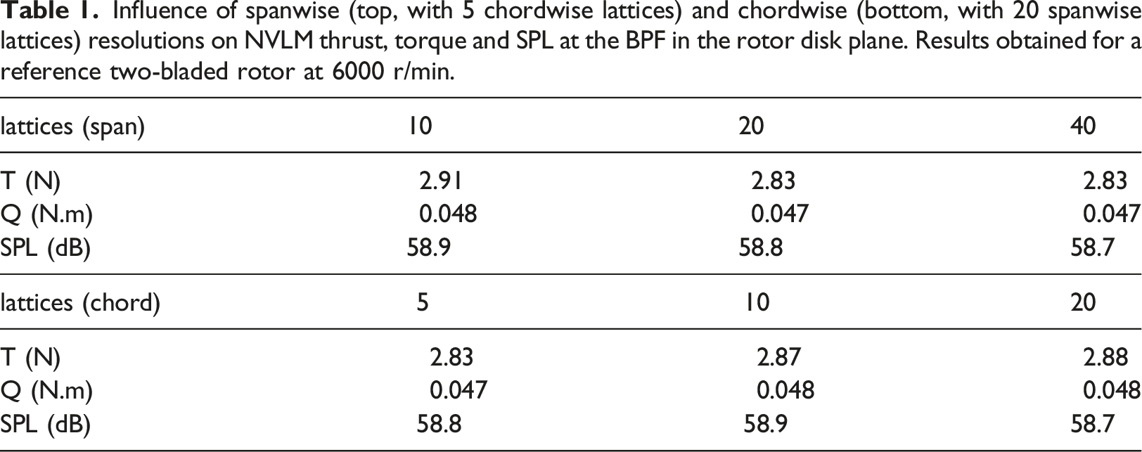
Time integration is performed using a fourth order Runge-Kutta scheme and with a time step corresponding to a 10° rotation of the rotor. Simulations are run for a number of rotations which ensure that initial transients have sufficiently decayed (typically around 20 rotations) and statistics are obtained from temporal signals over at least 5 rotations. The CPU time required to simulate 20 rotations is approximately 80 core-hours.
Navier-Stokes simulations
Numerical simulations of the Navier-Stokes equations are then considered. The Fluent 18.0 code is used, which employs a cell-centered finite volume method to solve the incompressible momentum and continuity equations in an uncoupled way, using a predictor–corrector approach. Specifically, the SIMPLE algorithm is used and second order schemes are used for spatial discretization with gradients evaluated using a least-squares method and the Gram-Schmidt process.
No turbulence model is used and hence the dissipation of turbulent scales smaller than the local cell size results from numerical dissipation. This approach is referred to as iLES in what follows.
The rotor is embedded in an inner cylindrical domain with dimensions 2.8 R × 0.7 R (width × height) that rotates in an outer, fixed cylindrical domain with dimensions 32R × 40R (width × height), as shown in Figure 2. Upper, lower and lateral boundaries are treated as pressure inlet, pressure outlet and slip wall, respectively. No-slip wall boundary condition is applied at the rotor surface. (a) Computational domain, (b) polyhedral and trimmed cells in a cross section of the inner and outer regions of the mesh and (c) close-up view of the mesh at the blade surface.
Influence of spatial resolutions on iLES thrust, torque and SPL at the BPF in the rotor disk plane. Results obtained for the reference two-bladed rotor at 6000 r/min.

We note that a full rotation is discretized into 400 time steps and that present results are obtained after 80 rotations which ensure that initial transients have sufficiently decayed. Statistics are obtained from temporal signals spanning at least 5 rotations. The CPU time required to simulate 80 rotations is approximately 11,800 core-hours.
Similarly to NVLM, wall pressure signals obtained from iLES are then propagated to the positions of the microphones described previously, using Farassat 1A formulation of the Ffowcs-Williams and Hawkings analogy.
Ffowcs-Williams and Hawkings analogy
For both NVLM and iLES, the retarded-time Farassat 1A formulation of the Ffowcs-Williams and Hawkings analogy is used to propagate sound sources from the rotor to the farfield (i.e. at a radial distance of 1.62 m from the rotor center, every 10° from −60° downstream to 60° upstream of the rotor disk plane). Neglecting quadrupole sources (given the low Mach number), the pressure flucutation at the farfield results from the linear combination of blade surface (S) integrals for thickness 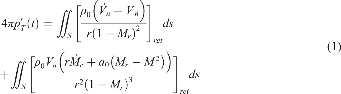
and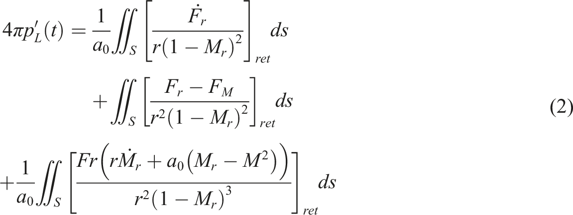
a0 and ρ0 denote the farfield speed of sound and fluid density, respectively. r is the distance between the source and the observer. M and V are Mach and velocity vectors of the surface element, respectively, with ⋅ and subscripts r and n denoting derivative with respect to the source time and projections along the source-to-observer and normal to surface element directions, respectively. F is the pressure force acting on the surface element, with components F r and F M when projected along the source-to-observer and surface motion directions, respectively. The ret subscript means that quantities in square brackets are evaluated at the retarded time.
Two-bladed rotor
Aerodynamics
Figure 3(a) displays the thrust as a function of the rotation speed obtained for the reference two-bladed rotor with AR = 5. Results from NVLM and iLES are compared to those from experiments obtained using the two test benches and for three different runs on the second test bench (repeatability tests). Reasonably good agreement is observed between all approaches providing that at these scales, manufacturing processes may have a significant influence on aerodynamic performance.15,34 For example, NVLM and iLES thrust values at 6000 r/min are 5.6% and 0.4% away from the first test bench experimental value, respectively. This is in line with previously reported results at similar Reynolds numbers.35,36 The relatively good approximation of a pure quadratic fit of the form T = a × RPM2 (with a ≈ 0.7978 × 10⁻⁷ and R2 = 0.999 for this case) obtained on experimental data from the first test bench indicates that effects due to variations in Reynolds and Mach numbers and deformations of the blades, for example, are of second order here. We stress that this may not always be the case, as previously observed for example on the APC 11 × 4.7SF off-the-shelf propeller.14,15,34 Figure 3(b) also shows reasonable agreement between experimental and numerical torque values. However, the approximation of a pure quadratic fit of the form Q = a × RPM2 (with a ≈ 0.1222 × 10⁻⁸ and R2 = 0.994 for this case) is not as accurate as that obtained for thrust values. (a) Thrust and (b) torque as a function of rotational speed obtained through experiments, NVLM and iLES for the two-bladed rotor.
Figure 4 depicts instantaneous Q-criterion isosurfaces and pressure isolines and contours at the blade surface obtained from iLES at 6000 r/min. A relatively strong vortex forms at the blade tip, delimiting the rotor wake that contracts as it is advected downstream of the rotor. The close-up view at the blade tip, shown as an inset in the figure, shows irregular patterns in pressure contours that indicate flow separation and subsequent unsteadiness in this region. The radial location of flow separation appears to be correlated with that of the tip vortex from the preceding blade. This causes temporal variations in local sectional forces. However, the impact on the overall thrust is negligible, with standard deviation equal to 1.5% of the time-averaged value and maximum instantaneous deviations below 3%. Instantaneous Q-criterion isosurfaces and pressure isolines and contours at the blade surface obtained from iLES for the two-bladed rotor at 6000 r/min. The rotor is seen from the top. The inset is a close-up view of the wing tip.
Figure 5 shows the sectional thrust distributions obtained from NVLM and iLES. The black and gray solid lines are time-averaged and instantaneous distributions from iLES, respectively. It can be observed that instantaneous deviations with respect to the time-averaged value can be significant in the outboard region, especially near the tip (beyond r/R ≈ 0.8) where flow separation was observed on Figure 4. For example, instantaneous values of sectional thrust L at r/R = 0.94 range between −11.3% and +8.8% of the time-averaged value. The black dashed line corresponds to the time-averaged distribution from NVLM. Again reasonable agreement is observed with iLES results; the sectional thrust increases roughly quadratically with r/R (according to the linear increase in local blade speed), peaks around r/R = 0.9 and drops at the very wing tip. However, NVLM overpredicts iLES sectional lift over most of the blade span, which leads to differences in overall thrust on the order of 5%. In addition, NVLM is unable to predict unsteady flow separation, as observed near the blade tip with iLES. Hence, although NVLM does predict slight time variations in sectional lift, there amplitude is small and not visible on Figure 5. Finally, it is found that the sectional lift distribution can be approximated by a concentrated force located at r/R = 0.8 (i.e. Instantaneous (grey) and time-averaged (black) radial thrust distributions obtained with iLES (plain) and NVLM (dashed) computations for the two-bladed rotor at 6000 r/min.
Comparison between thrust and torque obtained from experimental and numerical approaches for the two-bladed rotor at 6000 r/min.

Overall, it is observed that both iLES and NVLM approaches provide reasonable estimates of aerodynamic performance as compared to experimental data. We stress that this test case is particularly stringent since it exhibits high viscous effects, flow separation at the wing tip and presumably non-negligible rotational effects due to the relatively low aspect ratio (e.g. Kruyt et al. 31 ; Jardin 32 ).
Acoustics
In this section, we focus on the farfield aeroacoustics of the two-bladed rotor. Figure 6 displays SPL obtained through experiments, NVLM and iLES at 6000 r/min in the rotor disk plane (0° azimuthal location). Corresponding time pressure signals are shown in the appendix. The experimental spectrum is characterized by a large tonal peak at the BPF and harmonics, as well as significant broadband noise in the range f ∈ [103−2 × 10⁴] Hz (recall that the anechoic chamber is acoustically treated in the range 80 Hz–16,000 Hz). The amplitude of the broadband noise is maximum around 104 Hz. In addition, a peak at the rotation frequency is observed, which can partly be attributed to imbalance in the experimental setup. Tonal peak at the rotation frequency induces beating frequencies between peaks at the BPF and harmonics. Farfield acoustic spectra obtained through experiments, NVLM and iLES for the two-bladed rotor at 6000 r/min in the rotor disk plane.
The iLES spectrum captures the amplitude of the BPF and of its first harmonic with reasonable accuracy. Specifically, values of 60.4 and 43.7 dB are predicted, which is 1.8 and 1.1 dB away from the experimental data, respectively. In addition, the rise in broadband noise around f = 103 Hz is also captured although it is overestimated as compared to experimental data and drops at much lower frequencies, i.e. around f = 3 × 10³ Hz. We note that this frequency is much lower than the cut-off frequency resulting from spatial and temporal discretization of the computation. On the other hand, iLES fails to predict the low frequency broadband noise. This is probably due to the FWH approach employed here which only considers pressure contributions at the blade surface. Mankbadi et al 3 recently showed through numerical simulation that the rotor wake significantly contributes to this low frequency broadband noise.
The NVLM spectrum is also depicted. It is shown that NVLM also provides reasonable predictions of the amplitude of the BPF (58.8 dB) and of its first harmonic (41.3 dB) which are 3.4 and 3.5 dB away from the experimental data, respectively. However, it is not capable to predict low and high frequency broadband noise which presumably arises from rotor wake and trailing edge turbulence. That is, noise resulting from flow unsteadiness only arises from the impact of BVI and vortex interactions (mutual induction) in the wake on blade loading, which thus appears to be much lower than rotor wake and trailing edge noise. Such methods should thus be enhanced with broadband noise models to accurately predict the overall sound pressure level.
Figure 7 plots the directivity of the BPF obtained through experiments, NVLM and iLES at 6000 r/min. The rotor wake is directed downwards (towards negative azimuthal coordinates). Data from experiments show that the amplitude of the BPF is maximum in the rotor disk plane (0° azimuthal location) and larger at downstream locations than at upstream locations. Specifically, the amplitude of the BPF is 44.5 and 52.6 dB at 60° and −60°, respectively. This pattern is found to be reasonably well predicted by iLES. Because noise from the rotor wake is not taken into account here (only pressure fluctuations at the blade surface are propagated through FWH), differences in SPL observed between downstream and upstream locations can presumably not be attributed to additional noise contribution from the rotor wake downstream. Similar observations can be made from NVLM results. However, it is observed that NVLM underpredicts SPL at upstream locations, which may result from the inability of the method to capture flow separation at the wing tip (previously observed on Figure 4). Yet, overall, it is noted that numerical approaches demonstrate reasonable accuracy at downstream locations, which is convenient from a practical perspective since most applications are concerned with noise generated in this region. Directivity plot of the BPF obtained through experiments, NVLM and iLES for the two-bladed rotor at 6000 r/min.
The contributions of loading and thickness noise to the directivity of the BPF obtained with iLES is depicted in Figure 8. It is shown that thickness noise dominates loading noise for azimuthal locations greater than approximately −25° while loading noise dominates thickness noise for azimuthal locations lower than −25°. Accordingly, the general trend of the SPL at the BPF observed on Figure 7 follows that of the thickness and loading contributions above and below −25°, respectively. Loading and thickness contributions to the directivity plot of the BPF obtained through iLES for the two-bladed rotor at 6000 r/min.
The directivity of the first harmonic of the BPF is displayed in Figure 9. SPL are found to be lower than those at the BPF with a maximum value at 0° and a ‘kink’ around 30° azimuthal locations. Again, iLES is found to predict the general trend within reasonable accuracy. Conversely, although it approximates experimental data around the rotor disk plane, NVLM demonstrates strong discrepancies with experiments at upstream and downstream locations. Directivity plot of the first harmonic of the BPF obtained through experiments, NVLM and iLES for the two-bladed rotor at 6000 r/min.
Overall, both iLES and NVLM provide fair approximations of thrust, torque and sound pressure levels at the BPF in the rotor disk plane and below, which are crucial metrics in the design of stealth and efficient rotors. In the next section we therefore use these approaches to assess the influence of rotor solidity on the aerodynamics and aeroacoustics of small scale rotors.
Influence of rotor solidity
Summary of cases.
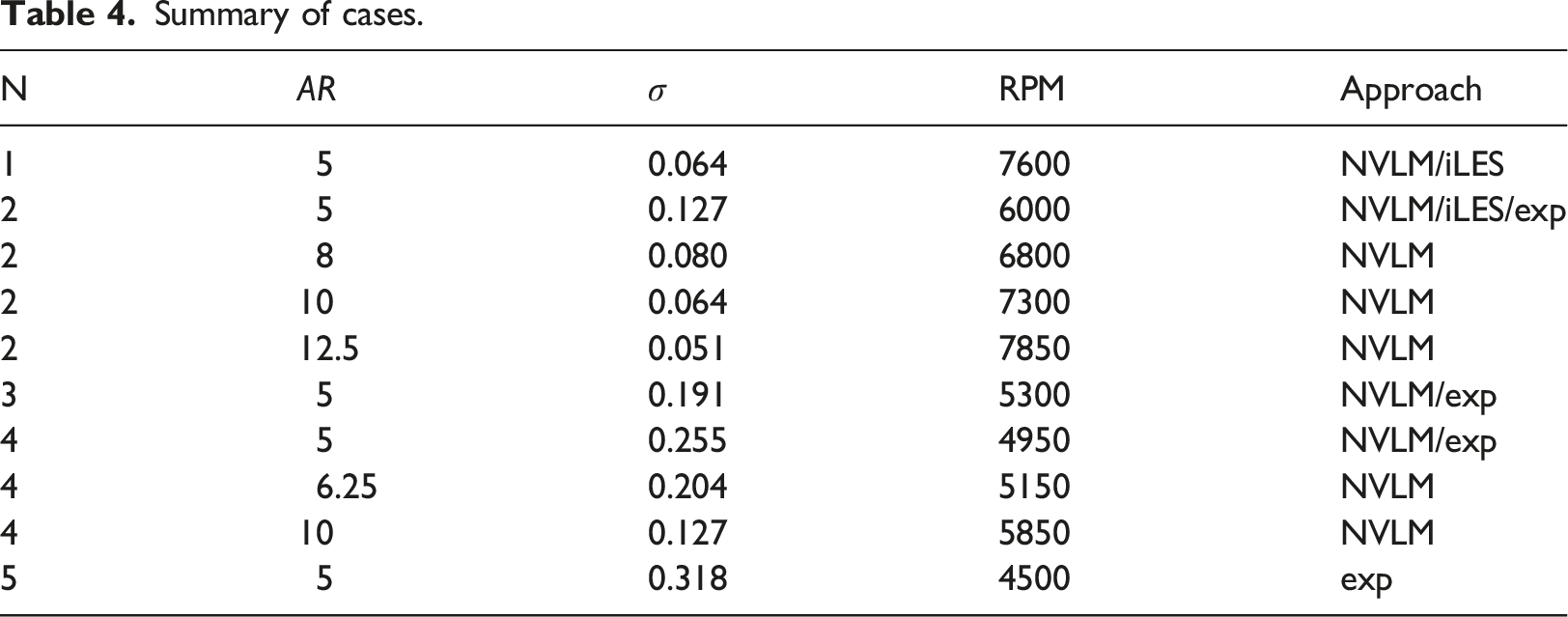
Variable N, constant AR
We first consider rotors with N = 1, 2, 3, 4 and 5 blades at 7600, 6000, 5300, 4950 and 4500 r/min, respectively. The blades’ aspect ratio is kept constant (AR = 5), hence rotor solidity increases with N. Note that experiments were not performed for N = 1 due to the inherent imbalance in the experimental setup and potentially high resulting vibrations and that thrust and torque measurements for N > 2 were only conducted on the second test bench (see Gojon et al 15 for further details). In addition, experiments may not be conducted at the exact RPM values mentioned above (which ensure a target thrust within a given tolerance) and hence values of thrust T, power loading PL (PL = T/Qω, where Q is the torque and ω is the rotation speed) and SPL are interpolated values from those typically obtained between 2000 and 8000 r/min every 500 r/min.
NVLM becomes particularly appealing as N increases because it does not suffer from numerical dissipation, conversely to iLES which requires high resolution between the blades to properly model BVI. In addition, because iLES requires very high resolution at the blade surface to accurately capture boundary layers, an increase in N further increases the computational cost, which in turn becomes hardly tractable. For that reason iLES simulations were only performed for N = 1 and N = 2. We also note that NVLM results were not obtained for N = 5 due to numerical stability issues.
Figure 10 plots the thrust and the power loading as a function of N. It is shown that the iso-thrust condition is relatively well verified. For example, thrust values from NVLM match their mean Thrust and power loading as a function of the number of blades (AR = 5).
Conversely, the increase in N has a significant impact on farfield aeroacoustics. Figure 11 displays the amplitude of the BPF as a function of N, obtained at azimuthal location 0° through experiments, NVLM and iLES. Again, a relatively good agreement is observed between all approaches, with the SPL drastically decreasing as N increases. Specifically, the one-bladed rotor generates 67 dB at 7600 r/min (data from NVLM) and the five-bladed rotor generates 28 dB at 4500 r/min (data from experiments). SPL in the rotor disk plane at the BPF as a function of the number of blades (AR = 5). Loading and thickness contributions from NVLM are depicted with dashed and dotted lines, respectively.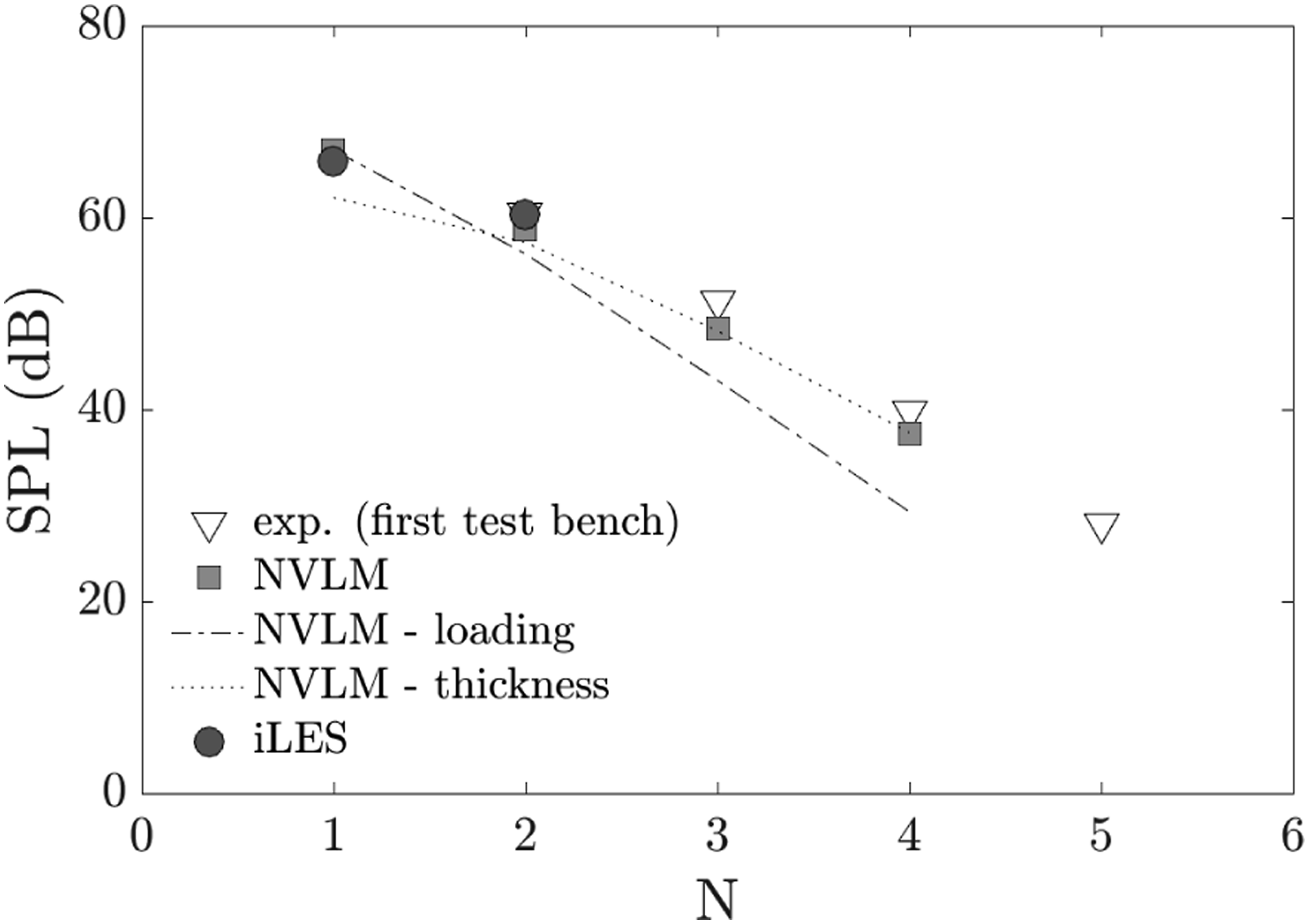
Dotted and dashed-dotted curves on Figure 11 depict the contributions of loading and thickness noise, respectively, on the amplitude of the BPF obtained from NVLM. It can be observed that while both contributions are on the same order of magnitude for N = 2, the amplitude of the BPF is dominated by loading noise for N < 2 while it is dominated by thickness noise for N > 2. The trend of the loading noise versus N curve is straightforward, i.e. it decreases with blade loading. On the other hand, the trend of the thickness noise versus N curve results from two competing trends, i.e. a decrease due to a lower rotation speed and an increase due to a larger rotor solidity. This explains why thickness noise eventually takes over loading noise as N increases.
Variable AR, constant N
We now consider two-bladed rotors with blades’ aspect ratio AR = 5, 8, 10 and 12.5 operating at 6000, 6800 7300 and 7850 r/min, respectively. Figure 12 shows the thrust and the power loading as a function of AR. The iso-thrust condition is verified within 0.3%, i.e. thrust values for different AR do not differ from their mean Thrust and power loading as a function of the aspect ratio (N = 2).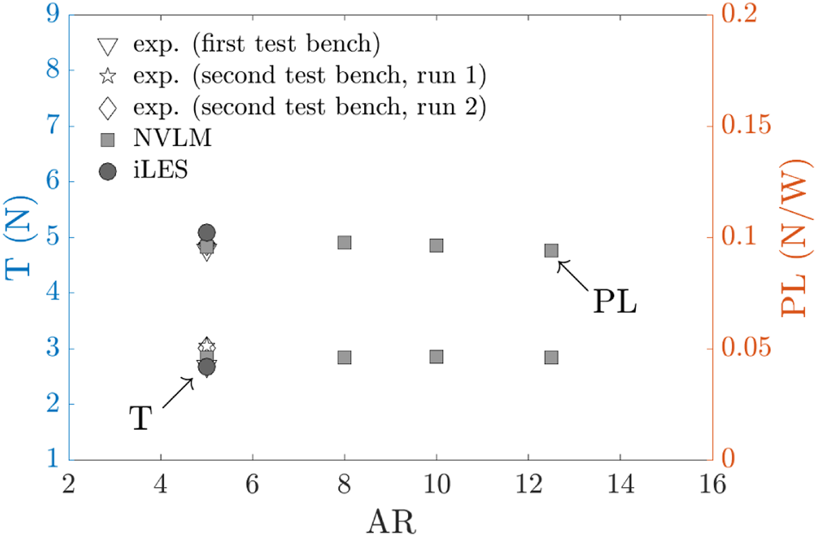
Similarly, Figure 13 shows that the influence of AR on the amplitude of the BPF in the rotor disk plane is not significant. Here it can be observed that the reduction in rotor solidity with increasing AR leads to a reduction in thickness noise, despite the increase in rotational speed required to achieve the target thrust. Therefore, while loading and thickness contributions are of the same order of magnitude for AR = 5, loading noise is found to dominate the aeroacoustic footprint at the BPF for larger AR. These results are in line with previous observations for different number of blades, with loading and thickness contributions being dominant at low and high rotor solidity ratio, respectively. SPL in the rotor disk plane at the BPF as a function of the aspect ratio (N = 2). Loading and thickness contributions from NVLM are depicted with dashed and dotted lines, respectively.
Overall analysis
Data are displayed all together on Figure 14, which plots SPL at the BPF in the rotor disk plane as a function of the rotor solidity ratio. Cases with N = 4 and AR = 6.25 (5150 r/min) and N = 4 and AR = 10 (5850 r/min) are added to the previous dataset, see Table 4. We note that the N = 2 and AR = 5 case and the N = 4 and AR = 10 case on the one hand and the N = 1 and AR = 5 case and the N = 2 and AR = 10 case on the other hand, have the same solidity ratio. The dashed line on Figure 14 is a linear regression of data at AR = 5 and the plain lines are the mean of data at N = 2 and N = 4. SPL in the rotor disk plane at the BPF as a function of the solidity ratio. Plain and dashed lines depict constant and linear trends obtained at constant N and constant AR values, respectively.
Figure 14 highlights the fact that SPL at the BPF decreases as σ increases when N increases at constant AR (dashed line) while it does not significantly vary as σ increases when AR decreases at constant N (plain lines). This indicates that, within the cases tested here, SPL at the BPF is not solely driven by σ. In addition, because the rotation speed varies inversely to the variation in σ to achieve a given target thrust, SPL at the BPF is not solely driven by RPM either. Rather, there exists an interplay between solidity and rotation speed effects that renders the evolution of SPL non trivial. More specifically, the iso-thrust condition leads to RPM varying inversely to σ, resulting in two competing trends in the generation of thickness noise (i.e. thickness noise decreases with σ but increases with RPM if all other parameters are kept constant). Moreover, as previously highlighted, SPL at the BPF results from the relative contribution of thickness and loading noise, which is here found to depend on σ. This can be observed on Figure 15 which plots the ratio between thickness and loading SPL at the BPF in the rotor disk plane as a function of σ, where the data appear to cluster around a linear trend. The transition between loading and thickness dominated noise lies around σ ≈ 0.12. Ratio of thickness-to-loading SPL in the rotor disk plane at the BPF as a function of the solidity ratio.
Comparable trends to those obtained in the rotor disk plane (previously shown in Figure 14) are observed at dowstream and upstream observer locations −30° and 30°, respectively. Yet, it can be seen that when N is kept constant, SPL tend to slightly decrease with σ at −30° while they tend to slightly increase at 30°, see Figure 16. This slight change in the evolution of SPL (with respect to the results at 0° observer location) presumably arises from variations in SPL ratios, with thickness noise being dominant at upstream locations and loading noise gaining relative importance at downstream locations (in that case dominant at low solidity ratio). Figure 17 shows that the SPL ratio versus σ curve is shifted towards higher SPL values as the observer moves upstream. Finally, we also note that the decrease in SPL with σ at constant AR is less pronounced at upstream observer locations. Same as Figure 14 at (a) −30° and (b) 30° observer locations. Same as Figure 15 at (a) −30° and (b) 30° observer locations.

Conclusion
Recent applications in the use of small size UAS have fostered the need to develop aerodynamically efficient and acoustically stealth propulsion sets. Accordingly, attention is currently being paid to advancing knowledge on the aerodynamics and acoustics of propellers and rotors at Reynolds numbers typical of small size UAS, typically in the range [103, 105]. At these Reynolds numbers, the flow may undergo laminar separation, laminar-to-turbulent transition and reattachment, leading to the formation of a so-called LSB with strong non-linear effects on aerodynamic performance, hence acoustics. The physics is very different to that observed at higher Reynolds numbers typical of large aircraft and helicopters which have been extensively studied in the past. It is not clear how this physics develops on small scale rotors/propellers and how experiments and numerical simulations compare given its sensitivity to operating conditions (e.g. freestream turbulence). The first goal of this paper is hence to compare medium (NVLM) and high (NS) fidelity numerical simulations with experiments conducted on small scale rotors operating under hovering flight conditions, at Reynolds and Mach numbers on the order of 105 and 0.2, respectively. In addition, small scale UAS may be characterized by different relative contributions of loading and thickness noise than those typically observed for larger aircraft and helicopters, hence different effects of rotor solidity ratio on noise generation. At iso-thrust conditions, a change in solidity ratio is associated with a change in rotor rotation speed, hence Reynolds number, which may further affect aerodynamic efficiency (and in turn noise emission) due to the sensitivity of the flow to the Reynolds number in this Reynolds number range. The second goal of this paper is thus to analyze the role of rotor solidity ratio, at iso-thrust condition, in the range of Reynolds numbers typical of small scale UAS.
We first showed that both aerodynamic performance and farfield tonal noise are reasonably well predicted by both numerical approaches. Conversely, both approaches fail to accurately predict broadband noise at low and high frequencies. On the one hand, while NVLM captures part of the flow unsteadiness arising from vortex interactions (mutual induction and interactions with the blades), it is not aimed at resolving boundary layers and thus at predicting potentially resulting high frequency trailing edge noise. Such methods should thus be enhanced with models for that purpose. In that regard, the use of Xfoil indirectly accounts for boundary layer separation, transition and reattachment and can help provide inputs to broadband noise models at relatively low cost. On the other hand, farfield noise was obtained by propagating pressure fluctuations from the blade surface (through FWH) and hence both approaches ignored wake noise which may contribute to low frequency broadband noise.
Second, we analyzed the effect of solidity ratio on the aerodynamic performance and farfield tonal noise of hovering rotors operating under iso-thrust conditions. It was shown that variations in solidity ratio have a negligible impact on aerodynamic performance. Conversely, SPL at the BPF were found to be drastically reduced when the solidity ratio was increased by increasing the number of blades at constant blades’ aspect ratio. Yet, this drastic reduction was not observed when the solidity ratio was increased by decreasing the blades’ aspect ratio keeping the number of blades constant. These trends in the evolution of SPL with solidity are partly driven by the interplay between thickness and loading noise at iso-thrust conditions. In addition, it appeared that, within the cases tested, the thickness-to-loading noise SPL ratios are largely driven by solidity.
Overall these results provide insight into the ability of numerical approaches to predict the farfield noise of low Reynolds number rotors and provide evidence for the influence of solidity on aerodynamic performance and acoustics in view of designing efficient and acoustically stealth rotors/propellers for small scale UAS. While medium-fidelity methods like NVLM can be used for such design phases due to their relatively low cost with respect to high-fidelity methods, they should include broadband noise models to properly account for the whole acoustic spectrum. This can be done without significant increase in computational cost by using additional inputs (i.e. boundary layer properties) from the ‘non-linear’ look-up tables built in Xfoil.
Footnotes
Acknowledgements
The authors greatefully acknowledge the Direction Générale de l’Armement (DGA) for funding this work. They are also grateful to national computing centers, part of the numerical work being conducted using HPC resources from GENCI-IDRIS and GENCI-CINES on Jean Zay, Occigen (Grant A0102A07178) and CALMIP on Olympe (Grant 2021-p1425).
Declaration of conflicting interests
The author(s) declared no potential conflicts of interest with respect to the research, authorship, and/or publication of this article.
Funding
The author(s) disclosed receipt of the following financial support for the research, authorship, and/or publication of this article: This work was supported by the Agence Innovation Défense (AID) de la Direction Générale de l’Armement (DGA).

Appendix
Figure 18(a) displays the time history of pressure fluctuation obtained in the rotor disk plane using experiments, iLES and NVLM for the two-bladed rotor at 6000 r/min. All signals exhibit a sinusoidal shape associated with the blade passing frequency. While the amplitudes of the sine signals are comparable, experiments are characterized by a clear modulation of the sine wave, at the rotational frequency. This highlights potential imbalance between the two rotor blades. Furthermore, experiments exhibit high frequency fluctuations that are not visible on NVLM and iLES pressure signals. The latter does exhibit small amplitude pressure fluctuations superimposed to the large amplitude fluctuations at the BPF, but which have typical frequencies much lower than those observed with experiments. Conversely, NVLM pressure signal is characterized by an almost pure sine wave. Time history of pressure fluctuation obtained using experiments, iLES and NVLM for the two-bladed rotor at 6000 r/min. Time is shown in its non-dimensional form t × RPM/60. The signals obtained (a) in the rotor disk plane and at (b) −30° are shown over two rotations.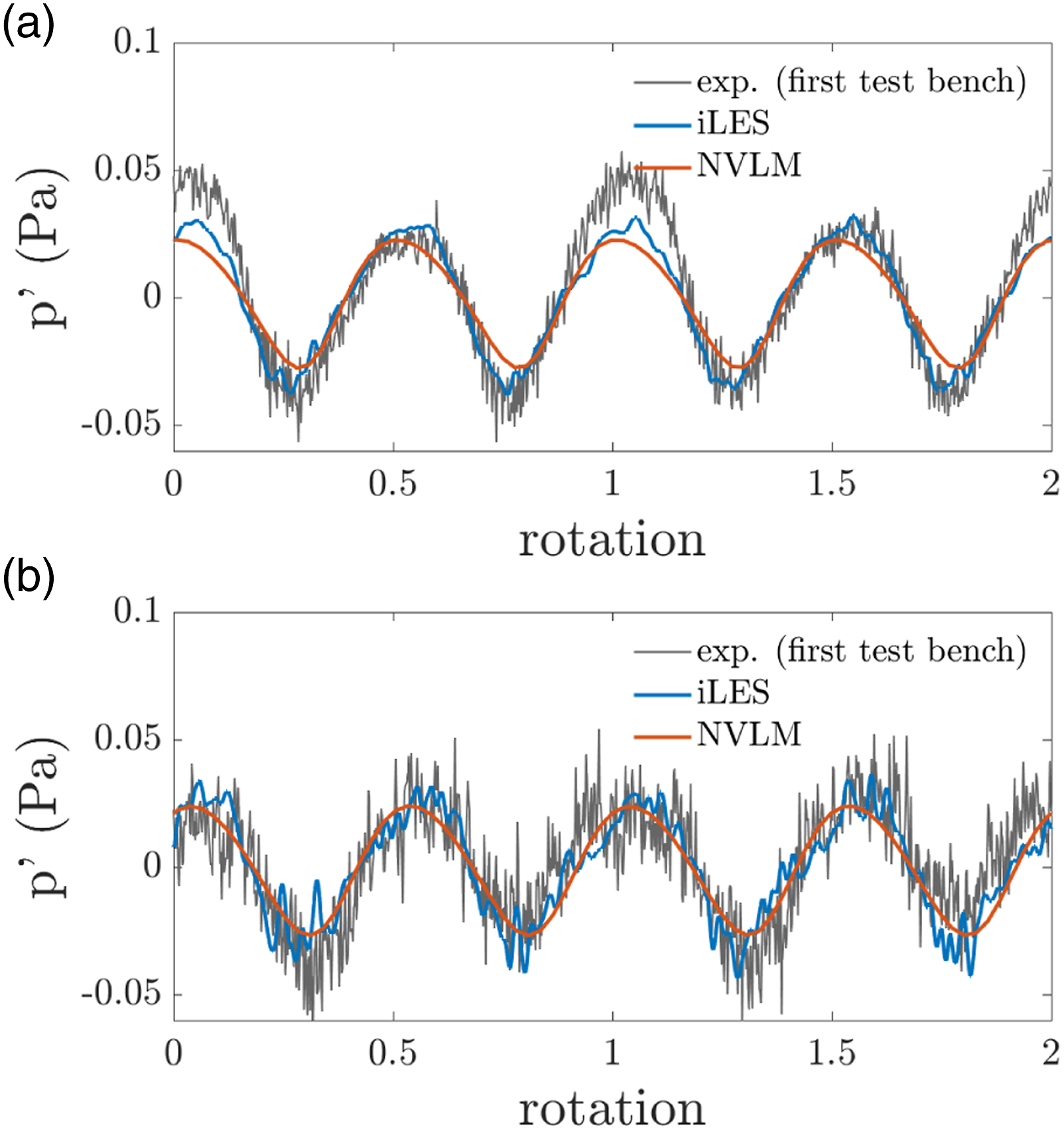
Similar observations can be made from Figure 18(b) which plots the time history of pressure fluctuation obtained at −30°, i.e. in the direction of the rotor wake. However, modulation of the BPF sine wave at the rotation frequency is not significant here.