



Abstract
Multi-rotor Unmanned Aerial Vehicles (UAVs) have become increasingly important in industries and early detection of structural damage is crucial to prevent unexpected breakdowns, ensure production efficiency, and maintain operational safety. This paper proposes machine learning techniques for detecting damage caused by loosened screws which is not easy founded based on vibration signals. An independent data acquisition device with a Micro Electro Mechanical Systems (MEMS) sensor is designed and fixed onto the multi-rotor UAVs to acquire the vibration data. Four machine learning algorithms, namely Support Vector Machine (SVM), K-Nearest Neighbor (KNN), Decision Tree, and Random Forest, are employed for damage detection. The results demonstrate successful utilization of the vibration data from the MEMS sensor for damage detection, with the random forest model outperforming other models with an accuracy of 90.07.
Keywords
Introduction
In the past decades,multi-rotor UAVs have been gaining more and more attention due to their increased application in all walks of life.1–3 The Multi-rotor aircrafts have rotating parts named propellers and always operate under complicated and diverse conditions, which makes them prone to failure and structure damage. 4 There have been many researchers focusing on the damage detection of UAVs,the next section will give a depict review of UAVs damage detection.
However, they are prone to structural damage such as parts loosening caused by the hostile environment and vibration from the propeller. 5 The structural health monitoring (SHM) system is of primary importance because structural damage may induce catastrophic damage to the integrity of the system. 6 Structural health monitoring(SHM) as a reliable and effective method for damage detection for structures has been a hot topic in the past few decades. 7 In the early years,the primary method for SHM was visual inspection which is both time-consuming and inaccurate. 8
With the emergence of big data and advanced sensing technology, machine learning (ML) methods have been adopted for SHM and expressed preferable advantages over traditional methods. ML methods can extract features from raw data and try to build some relationship with the output, therefore, ML methods can not only detect the damage but also judge the fault type. Vibration exists in every machine in the working environment. Different data types can be used for damage detection such as temperature, motor sound, motor current and vibration. 9 During machining operations, these vibrations are directly linked to problems in systems, especially for which have rotating or reciprocating parts. 10 Baskaya 11 and Bondyra 12 are all put forward an Support vector machine (SVM) model to detect propeller damage of multi-rotor UAV based on vibration signals collected by the onboard Inertial Measurement Unit (IMU) sensor.
A novel Healthy Monitoring (HM) system for UAV was presented to diagnosis electro-mechanical nose-landing gear door actuator faults.
13
Four damage modes were researched including motor degradation, friction induced failures, backlash and external perturbation effects. The current signals were collected, the normal condition and the fault condition with severe friction,as well as the difference among them can be shown in Figure 1 Current spectrum under normal and friction and the difference.
13
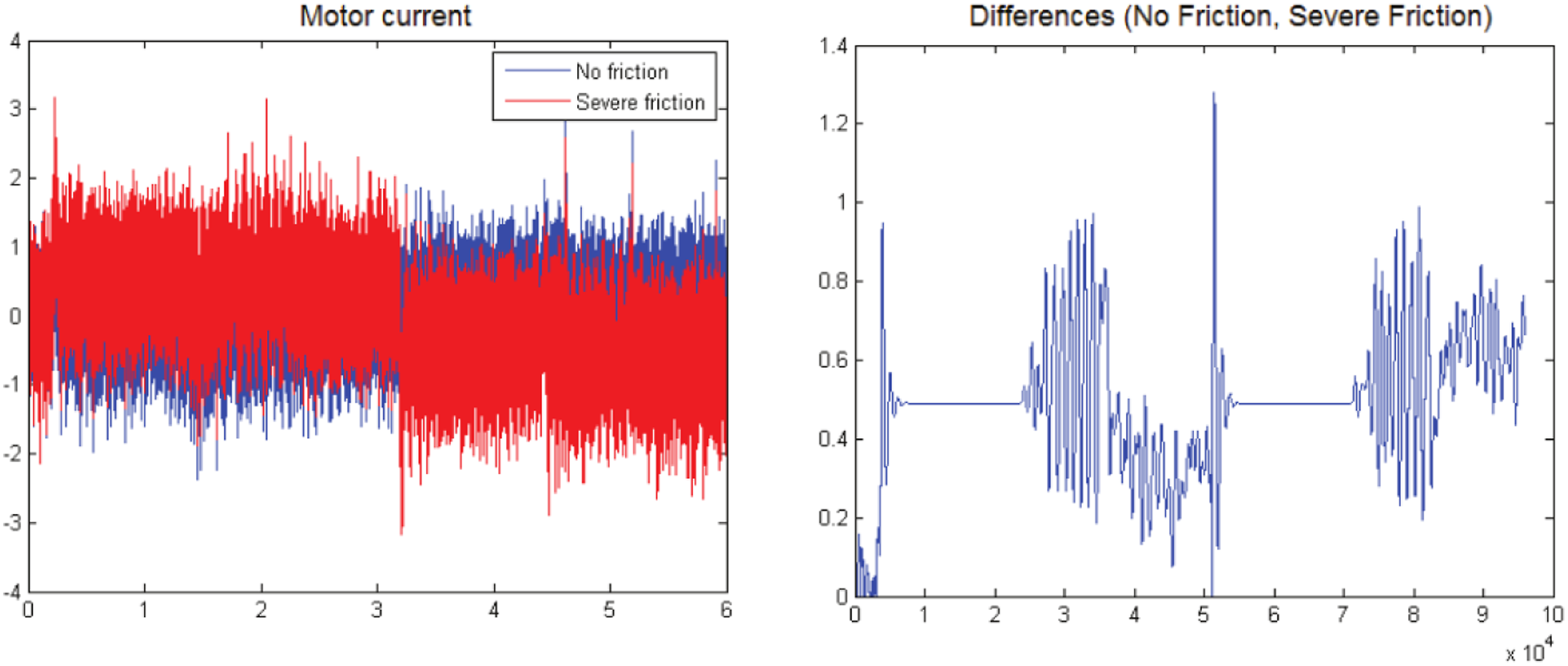
After the data collection, variety data-driven techniques were adopted based on machine learning including BayesNet, NaiveBayes, Decision tree, induction rules, K-Nearest Neighbors (KNN), logistic regression and Multilayer Perceptron, the results show that, the BayesNet has the highest performance with the accuracy closed to 90%. However, the research did not gave the way to acquire the current signals.
It turns out that different failure types have different vibration rules. Studies show much interests in damage detection and classification via vibration signals. For multi-rotor UAVs, getting the vibration data is a crucial problem, usually, it is hard to get the vibration data because there is no interface of the vibration data. 14 So, in this research, a vibration data acquisition device based on a MEMS sensor was fabricated.
This paper gives an introduction and review of the ML methods. As for machine learning, the foremost is “data”, for multi-rotor UAVs, it is a hugely challenging problem to get the vibration data, in this paper, a vibration data acquisition device based on a MEMS sensor is designed to collect the vibration data, this is also the innovation of the research. The research methodology was introduced in Section 3 as well as the designing of the vibration data acquisition device. The experimental setup was proposed in section 4, the damage case was simulated and the vibration data was collected under both undamaged and damaged cases. Section 5 gives a summary of the research and the future work also discussed in the section.
Machine learning algorithms for damage detection
ML methods can be divided into supervised learning and unsupervised learning. Supervised learning methods need to label the output so that the ML algorithms can find the internal connection, so supervised learning methods are usually used for classification (regression) and unsupervised learning for clustering, respectively. 15 Obviously, damage detection is a supervised learning algorithm. The classical ML methods including SVM, KNN, decision tree and random forest which are all supervised learning algorithms, this section will explain the principles of the four algorithms in detail.
Support vector machine
SVM was originally a classifier that evolved from the field of pattern recognition. Vapnik et al. began relevant research in 1963. 16 SVM was used initially for linear classification, but in many cases, it can not be entirely classified by linear. The training samples can be mapped to high-dimensional space through kernel function, and the construction of regression function can realize classification and data prediction.Worden 17 used the SVM to detect damage for ball bearings under five conditions and a framework structure for 17 states. Karabacak 18 adopted SVM to detect worm gearboxes fault under different conditions based on vibration, sound,thermal features and the results shows that SVM has almost equal performance with ANN.
In this research, triaxial acceleration data under damage and undamaged were plotted in a three-dimensional diagram as shown in Figure 2. Triaxial acceleration data under damage and undamaged.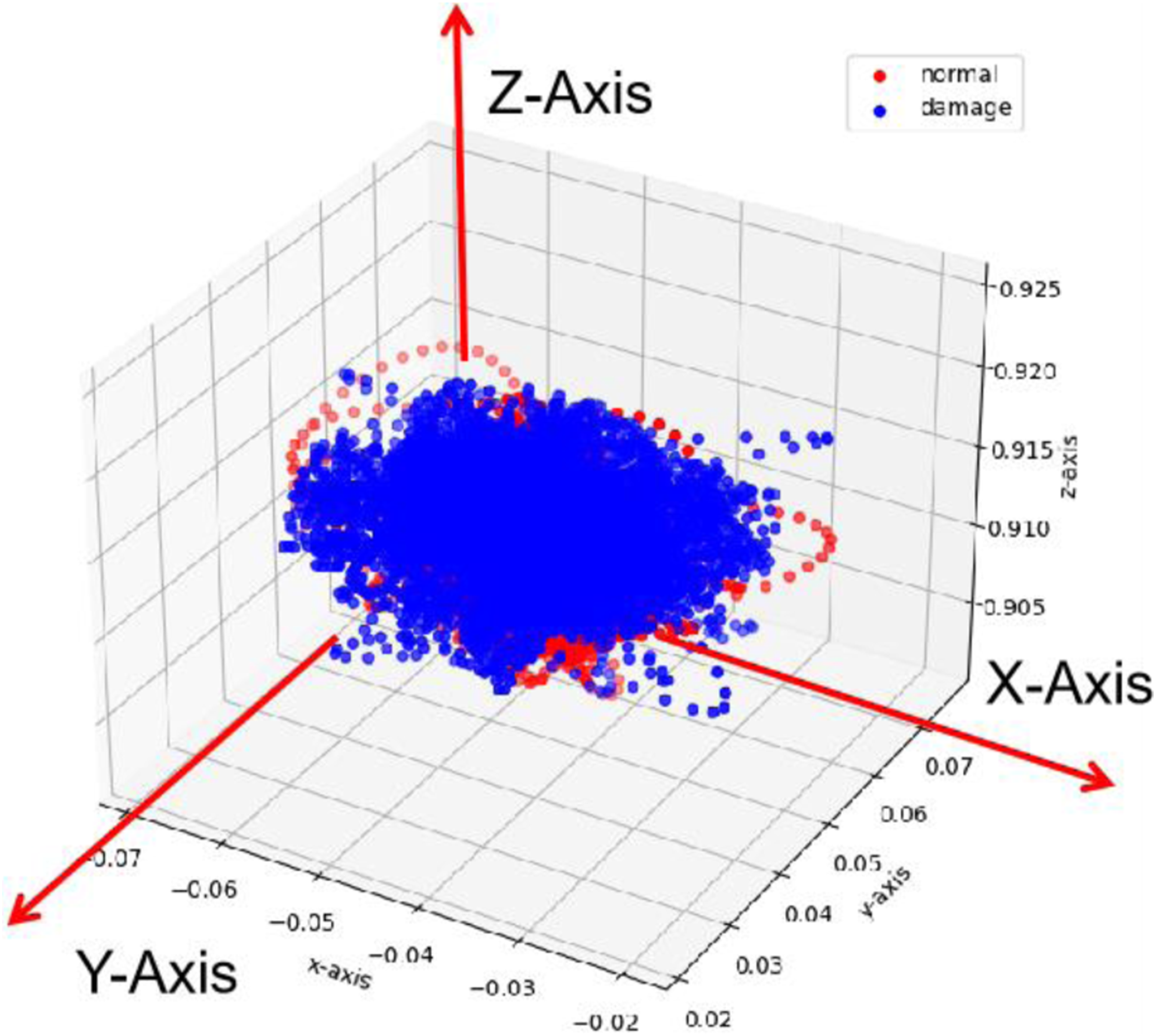
The principle of SVM for damage classification is to find a hyperplane to separate the two types of data,and the hyperplane can be defined as the following function
19
:


The lagrange multiplier method is applied in the solution process, and the standard format is:

Simplify the above formula to obtain Lagrange function:



Parameters used in SVM.

To be noted that,SVM can be used for binary classification, multiple SVM classifiers can be utilized for multiple classifications. 21
K-nearest-neighbours algorithm
The K-Nearest-Neighbours (KNN) algorithm is the most straightforward but efficient machine learning algorithm. 22 It has been widely used for damage detection. Paudyal 23 used KNN to identify unbalanced and misalignment faults for shafts based on vibration signals. The results show the accuracy can achieve 96%. Feng 24 also adopted the KNN algorithm to locate and quantify bridge damage.
The principle of KNN is depicted as follows:
In order to describe the principle of KNN more simply, only two axes of acceleration signals are employed and plotted in Figure 3, there are labeled data in the figure both damaged and undamaged, as well as one sample unknown which to classify. The purpose of the KNN is to determine which category this sample belongs to. In this picture, three (K value) labeled data closest to the unknown sample, they are damaged, damaged and undamaged, respectively. It is obvious that the damaged cases account for the majority. It is easy to understand the principle of the KNN. Principle of KNN algorithm.
However, there are two critical issues needed to be considered. One is how to define the “closest” to the unknown sample. Usually, the Euclidean distance was widely accepted, it can be defined as the following function:
Parameters used in KNN.

Decision tree algorithm
The decision tree is a classical methodology used for classification and has been widely used for damage detection and identification. It is first proposed to solve the classification tasks. 29 Gangadhar 30 used a decision tree to detect three damage cases of single point cutting tools and ball bearing faults were researched by Euldji 31 based on the decision tree.
Figure 4 shows the principle of the decision tree, where Schematic diagram of decision tree.
Entropy is a measure that describes the uncertainty of random variables, which can describe the internal chaos of a data set.Entropy 
Information gain 
To overcome the shortage, C4.5 algorithm adopted the Gain Ratio to select the feature. It can be define as follows:
The highest Gain Ratio was adopted in C4.5 to replace the information gain in the ID3 algorithm.
Gini index was another parameter used in the CART decision tree for selecting the best feature, the formula is given below:
In this research, CART decision tree was adopted, the process can be shown in Figure 5 Process of CART decision tree.

Random forests algorithm
The prototype of random forests algorithm was proposed by leo Breiman and Adele Cutler 39 and proceeded by Ho. 40 The “random” of random forest is mainly reflected in two aspects:one is the random samples, and another one is the random feature in the decision tree as shown in Figure 5. The random forests consists of many decision trees, as mentioned before, in the decision tree algorithm, the input is the whole data set, however,the input of the decision trees in the random forest is “random” and just a portion of the original data, the ration can be set when run the algorithm.
For example, 70% of original data can be used to construct the decision tree, the 70% data called InBag, the remaining 30% is the out-of-bag data, when the second decision tree is constructed, a new 70% data was selected, it is random, usually, it includes a portion of the 30% remaining data. It is a process of sampling with replacement also called bootstrapping.
41
Another “random” in the random forests is that the feature selection is random, in the decision tree algorithm, the best feature which can classify the training set effectively was selected first by the information gain or gain ratio discussed in the last section. However, the feature selection in the random trees is random, this can give other features the chance to classify the data and avoid overfit in the classification.42,43 The workflow illustrated in Figure 6. Workflow of random forests.
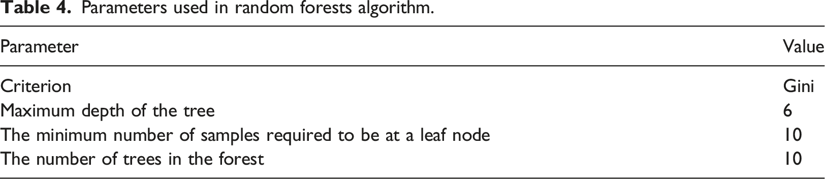
Parameters used in random forests algorithm.
Damage detection methodology
The methodology proposed in this research for UAV structural damage detection can be shown in Figure 7. Methodology for UAV structural damage detection.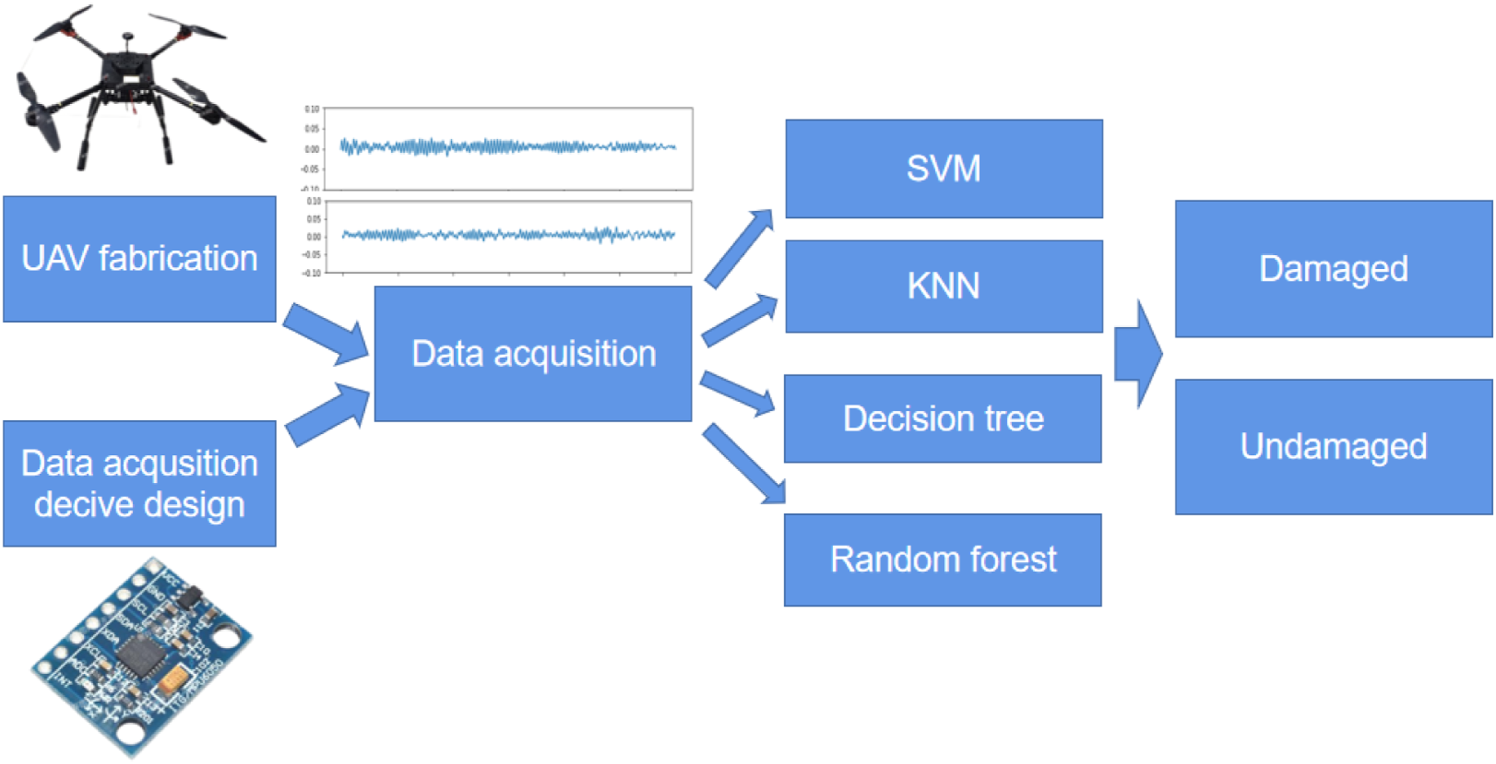
A quad-rotor UAV with a 900 mm wheelbase was fabricated as shown in Figure 8. The fuselage structure and propeller are made of carbon fiber materials which are light and robust. The top of the UAV has no extra parts which are easy to install the accelerometer. Quad-rotor UAV.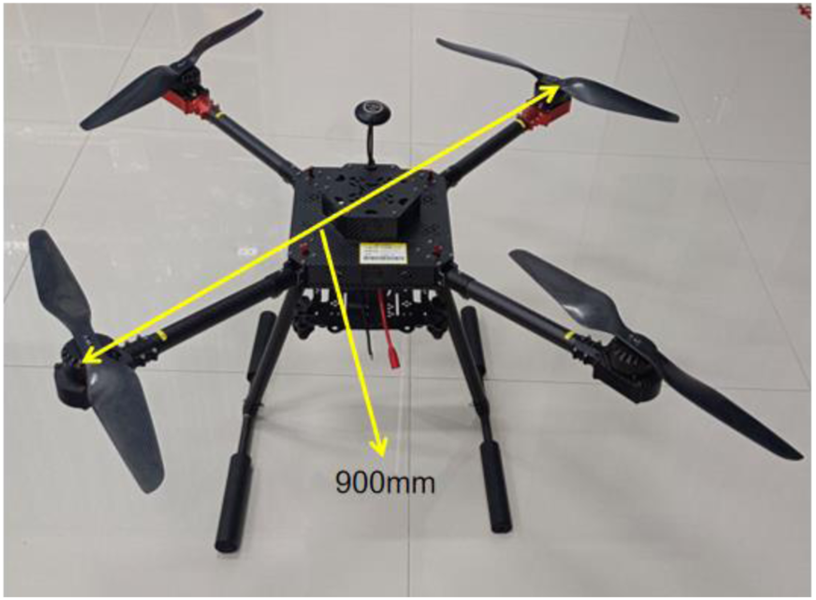
In this research, the vibration data was collected as the training set for damage detection, however, the vibration data can not be easy to acquire sometimes, it can be obtained from the Inertial Measurement Unit (IMU) but usually need an extra circuit, Zhang 44 used the vibration data to detect and identify the damage for UAV via LSTM network, but it did not give the illustration how to get the data.
To solve this problem,an independent vibration data acquisition device was fabricated based on MEMS sensor, this is one of the innovations of this research. The structure of the vibration data acquisition device can be illustrated in Figure 9. The structure of the vibration data acquisition device.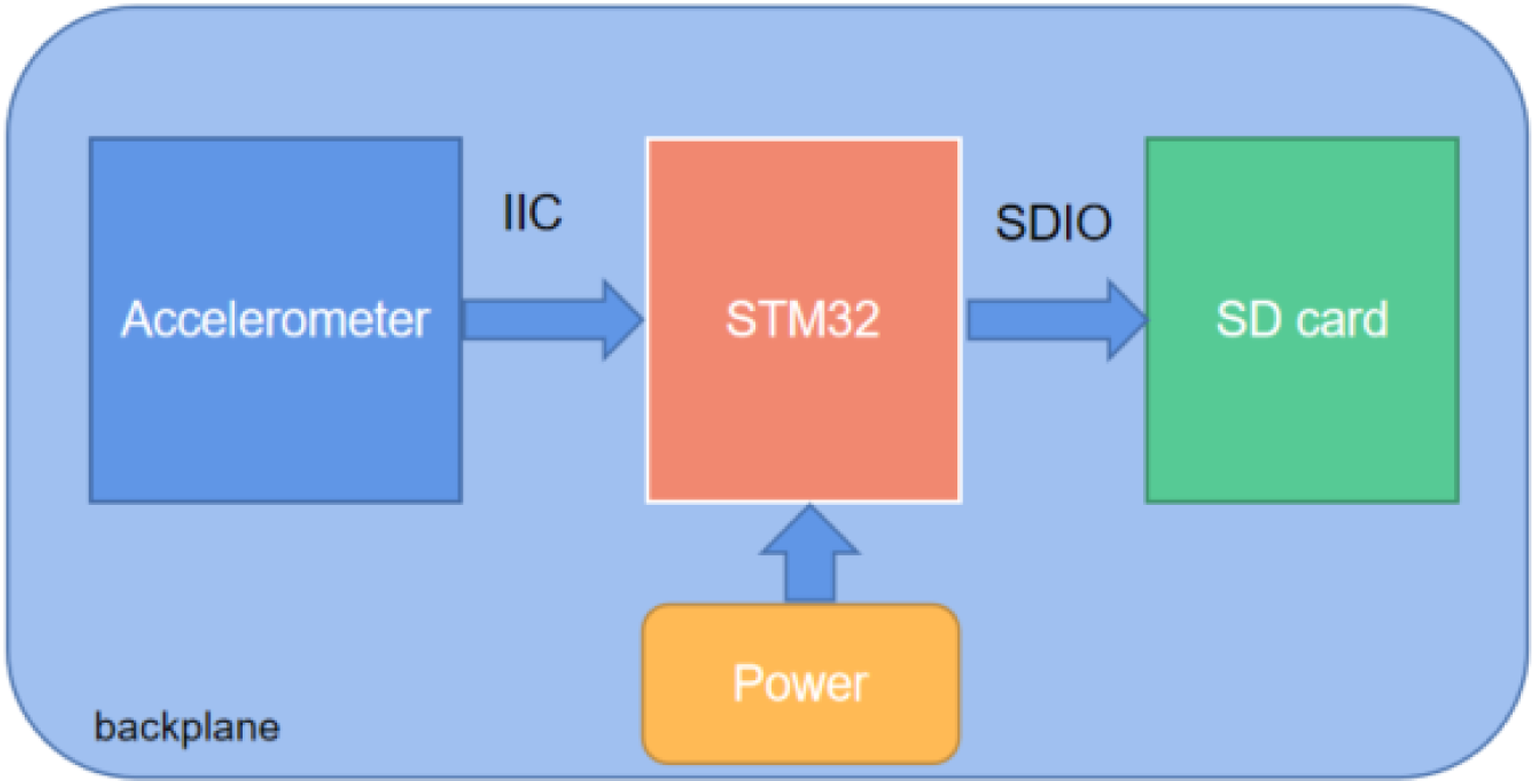
It can be seen from the figure that the device is mainly composed of three parts: accelerometer module, MCU module and SD card data storage module. The three modules are all located on the same backplane. There are many data interfaces on the backplane, such as Ethernet interface, USB interface, 2.4G wireless module interface, etc., which also facilitates the expansion of the system in the later stage. The whole system does not cross link with the aircraft, and can independently collect data. The following section will give a detailed introduction about the accelerometer and MCU.
Micro electro mechanical system (MEMS) is a single chip that combines mechanical and electrical components, usually at very microscopic scales and low price. MEMS sensor was adopted to collect the vibration data in this research. MEMS sensor has many advantages such as reliability, low power, small scale and cost saving.
45
The MEMS accelerometer was used to detect the damage of a vertical stabilizer from the A320 aircraft, the results show that although the MEMS accelerometer has a low price, but it has high performance.
46
MPU6050 as a MEMS accelerometer was utilized to collect the three axes acceleration of the UAV, MPU6050 has been widely used in the industry measurement due to its low scale, low cost and high performance.
47
Ismail compared two accelerometer sensors for water pipeline damage detection based on vibration data, namely, high sensitivity.
48
The image of MPU6050 and the performance comparison between MPU6050 and ADXL335 can be shown in Figure 10 MPU6050 sensor and performance comparison between MPU6050 and ADXL335.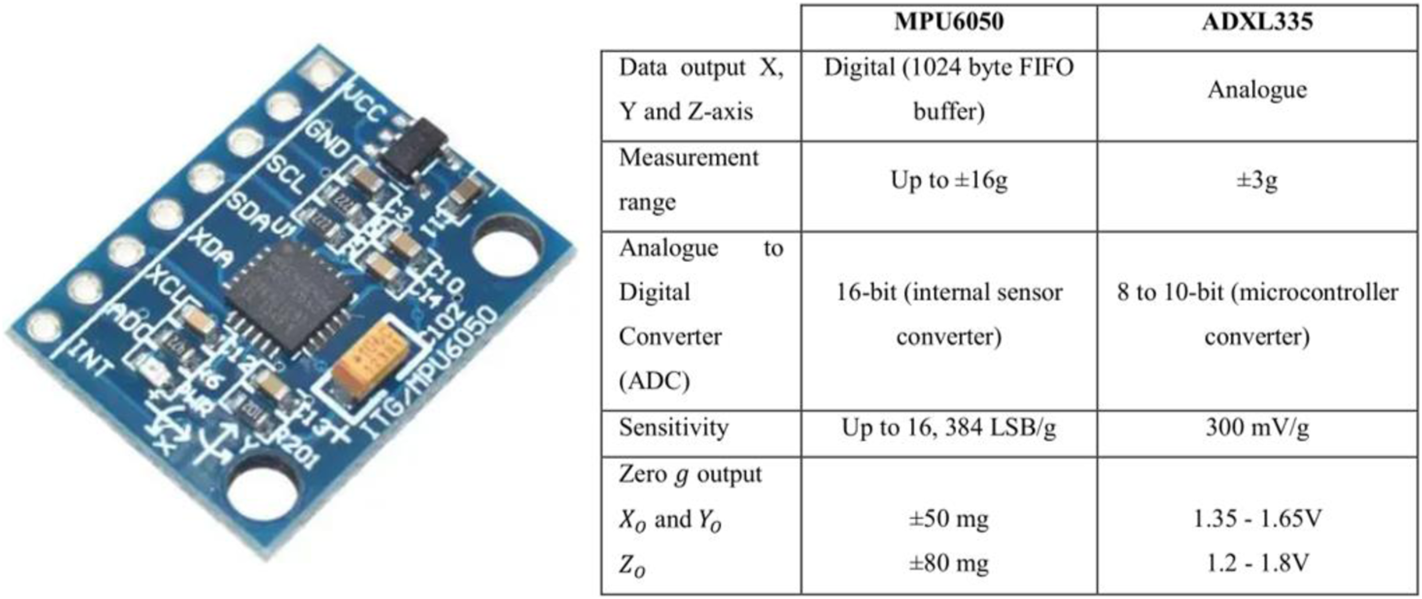
The micro-controller is responsible for connecting the sensors, communicating with the hardware, and collecting, processing and storing the vibration data. It is the core part of the data acquisition system, and a high-performance single-chip microcomputer must be selected. There are many micro-controllers that can realize this function, for example, PIC16f73 micro-controller was selected to collect the vibration data based on the ADXL335 accelerometer. 49 The Adruino ZigBee was adopted to process the data obtained from the MPU6050 sensor to monitor the water pipeline condition. 47
STM32F103 micro-controller was adopted because it has abundant peripheral resources and data bus interfaces, connecting various sensors and having a broader range of applications. Furthermore, the STM32 micro-controller has low cost and power consumption advantages.
The MPU6050 sensor was connected to the STM32F103 micro-controller via the IIC communication mode. The SD card module was integrated with the STM32 by the SDIO interface, which can store the vibration data. A 32 G memory card with a high read/write rate was utilized in the device.
50
The vibration data acquisition device can be shown in the Figure 11. Vibration data acquisition device.
The MPU6050 sensor can collect the three axes’ vibration data and store the vibration data on the SD card in the CSV format as shown in Figure 12. The saved vibration data.
Experimental validation
The vibration data was obtained under an undamaged and damaged case (loosened screw) shown in Figure 13. A screw was loosened to simulate the fault state. Experimental setup (a undamaged, b.damaged with loosened screw).
The vibration data acquisition sensor was bonded to the UAV and the direction of the x-axis is consistent with the UAV's head direction, as shown in Figure 14. All the data can be stored in the SD card installed on the STM32 single chip for future analysis. The installation of accelerometer.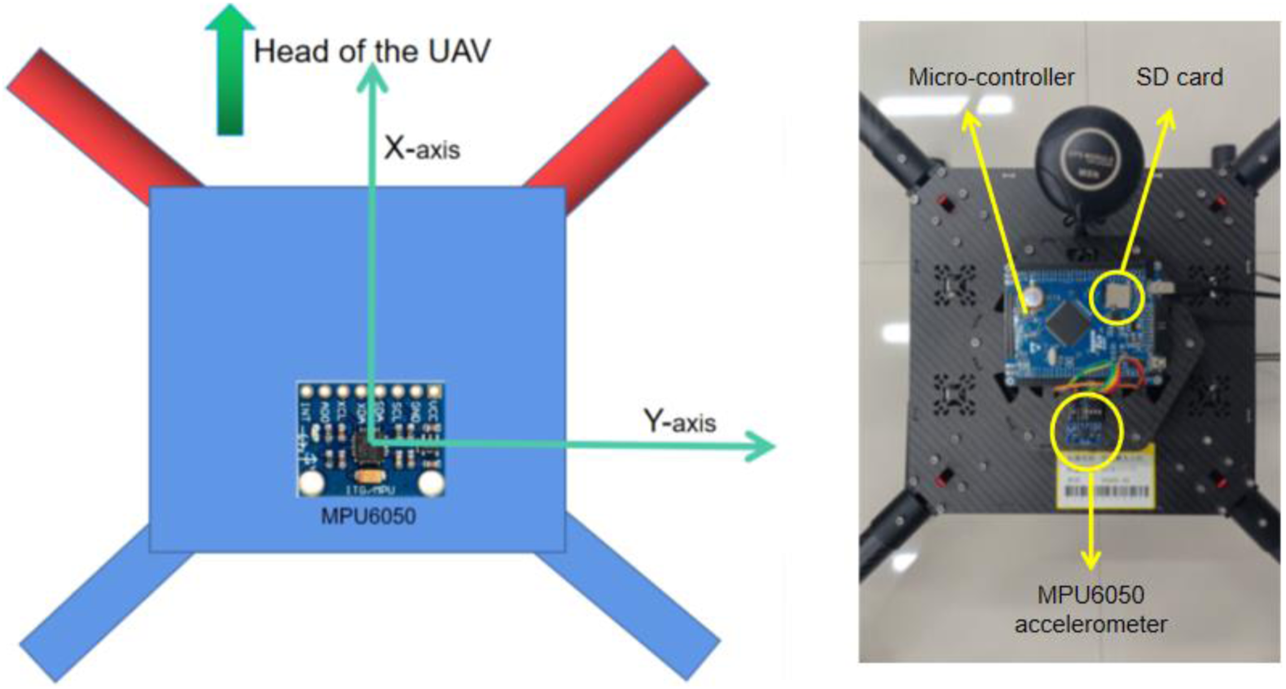
In consideration of potential artificial deficiencies, it is important to acknowledge that the aircraft is deemed unsafe. In order to prioritize safety concerns, the aircraft is confined to indoor environments, where it operates at idle speed. The sampling frequency of MPU6050 is 50H z, and the sampling period is 1/50 = 20 ms. Eight thousand samples of three axes vibration data were collected under undamaged and damaged cases. The original acceleration data are plotted in Figure 15 using the platform python. The raw three axes vibration data.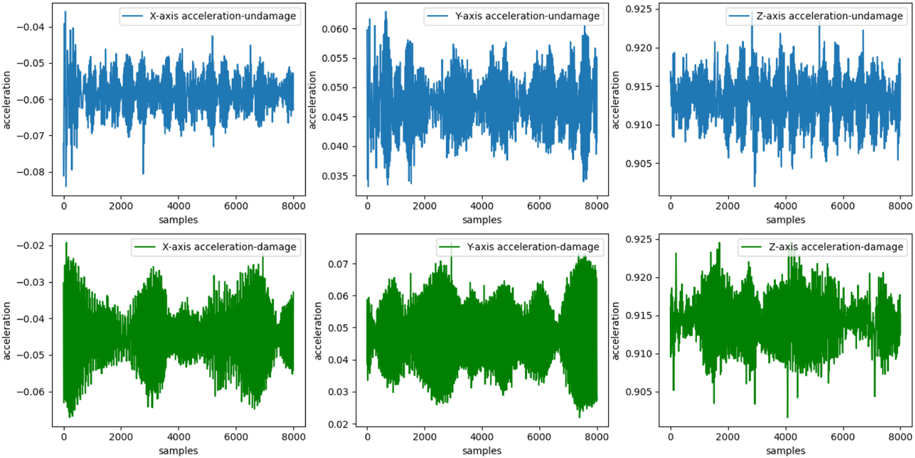
16 thousand sample vibration data were collected, and 4000 samples were used as the test set. Four machine learning models mentioned before were adopted for damage detection and classification. The results of the models can be illustrated using the confusion matrix as shown in Figure 15. The confusion matrix records the classification results of each state, including the number of correctly predicted and incorrectly predicted samples. The horizontal axis represents the prediction label of each state, and its vertical axis represents the actual label of each state, so the diagonal line predicts the correct number for each class. Figure 16 is the confusion matrix of damage detection results of the proposed machine learning methods. For the structural damage detection based on the SVM model, during the 2004 samples in the undamaged state, 1843 were judged to be correct and 161 was wrongly judged to be damaged which is the bolt loosened at the arm conjunction, as mentioned before. Confusion matrix of damage detection results.
The results show that the vibration collected by the fabricated vibration data acquisition device can be used for damage detection and the accuracy of the four models can be shown in Figure 17. Accuracy of different machine learning methods.
From Figure 17, it can be seen that the model of the random forest has the highest accuracy. However, the SVM model performed lower than the other three models.
Conclusion
This work proposes and discusses different machine learning methods for UAV damage detection based on MEMS sensors. A quad-rotor UAV was fabricated in this research and a screw was loosened as the damage case. In order to obtain the data which is essential for machine learning methods, a vibration data acquisition device was designed to acquire the three axes of vibration. Four machine learning methods, namely, SVM, KNN, Decision tree and random forest have been adopted to detect the damage based on the vibration data. The methods have been proved effective with the experimental results. From the results, each method can achieve an accuracy nearly 90%, and it can be seen that the random forest algorithm performed better than the other three methods and achieve an accuracy of 90.07%.
Although some achievements have been made in this work, several aspects still need to be researched in the future: (1) In this work, the vibration data is saved in the SD card firstly, so it is not a real-time condition monitor, future work maybe utilize the wireless transmission technology to realize the SHM in real-time. (2) The original vibration signals were used as the input of the machine learning algorithms. However, the feature extraction technology can be utilized to process the data, and the accuracy maybe improve. (3) Deep learning as a novel method has significant advantages in pattern recognition, future work will involve the technology.
Footnotes
Acknowledgments
The authors want to acknowledge the support of Universiti Teknologi PETRONAS under Yayasan Universiti Teknologi PETRONAS of grant number YUTP−FRG−015LC0−417.
Declaration of conflicting interests
The author(s) declared no potential conflicts of interest with respect to the research, authorship, and/or publication of this article.
Funding
The author(s) received no financial support for the research, authorship, and/or publication of this article.
